 Annapurna Kumari
- Department of Electronics Engineering, Indian Institute of Technology (Indian School of Mines), Dhanbad, Jharkhand, India
The real-time high-resolution target detection in radar applications has increased the demand for photonic radar systems due to their higher bandwidth and faster processing capabilities over conventional microwave radar. Additionally, photonic-based radar technology can revolutionize the limited performance of conventional microwave radar caused by various atmospheric attenuations. This article presents a frequency-modulated continuous-wave photonic radar system using coherent detection. The performance of the proposed system is theoretically investigated under the effect of various real-time atmospheric weather attenuations and the influence of solar background noise, which is further verified on the simulation platform. This study is conducted under different atmospheric weather conditions, such as clear, haze, and fog, to highlight the practical limitation of free-space links in the presence of solar background noise. The detected signal at different target ranges with and without solar noise is measured and then compared in terms of signal-to-noise ratio. Furthermore, the impact of solar noise on the system performance when the Sun is under different sky conditions and zenithal angles is also analyzed. The results presented here provide insights into designing photonic radar systems for practical applications like autonomous vehicle radar systems, self-traffic control, and navigation.
1 Introduction
Photonic radar is the next-generation radio detection and ranging system, which detects and precisely measures the range, velocity, angle, and coordinates of any target. In 1886, a German physicist first experimentally observed that radio waves are reflected by a solid body [1]. Based on this experiment, the concept of radar came into existence, where the electromagnetic waves are transmitted by the transmission antenna and the reflected echo from the target is received by the receiving antenna for further processing of echo in order to determine the target information. In the conventional radar system, when a continuous electromagnetic wave is transmitted all the time, it is known as continuous-wave (CW) radars. These CW radars are capable of detecting velocity by processing the Doppler frequency shift [2, 3]. Moreover, when the continuous-wave radar signal is frequency-modulated, it is known as frequency-modulated continuous-wave (FMCW) radars. In FMCW radars, the transmission signal changes its frequency linearly during the measurement according to a particular modulating pattern such as saw-tooth, triangular, or rectangular [3]. Linear FMCW radars can measure velocity as well as range of the target. In radio technologies, microwave and photonic system is setting new paradigms with improved performance and new applications [4, 5]. A new generation of multifunctional systems and advanced surveillance is being made possible by the use of photonics in radar systems [6]. Due to these reasons, microwave-photonic radar has attracted many researchers in the last few years all over the globe. Photonic approaches to generate and process linear frequency-modulated microwave signals with wide bandwidth at high frequency have been implemented for several radar applications [7]. Thus, microwave-photonic radar has potential to achieve high-range resolution, which is difficult for the conventional electronic radar system due to its limited bandwidth, low speed, and poor resolution [8, 9]. Photonic radar finds its application in the field of military surveillance [10], space application [11], high-resolution imaging [12], wireless local positioning systems, and intelligent autonomous transport systems [13]. The global positioning systems are limited to a marginal accuracy range and require high image resolution resulting in unreliable performance in urban areas, making the conventional electronic radar inappropriate for applications such as intelligence transport systems [14]. Furthermore, the beam divergence of conventional electronic radars is large, which makes them difficult to distinguish between two vehicles. On the other hand, due to the narrow linewidth of the operating laser, photonic radars have low beam divergence, which makes them suitable for automotive transport systems [15]. Thus, all these advantages make photonic radar a primary method for detecting targets with high resolution and accuracy [16]. Photonic radar can be implemented on the automotive transport system, where target information can be extracted by modulating radio frequency on the optical signal and transmitting over free-space optical links. The receiver then receives the reflected signal from the target and performs additional processing to determine that target information [17, 18]. In addition to this, photonic radar requires low input power than electronic radar, which makes it suitable for automotive transport systems [19].
The sweeping bandwidth and receiver signal-to-noise ratio influence photonic radar range accuracy [20]. Many photonic radar systems use high-precision short-pulse lasers with a low pulse repetition rate and extremely high pulse peak power to achieve high range accuracy, but the main concern in this type of system is photon damage due to peak power in the megawatt range, which gradually degrades the optics and ultimately shortens the system lifetime [21]. To solve this issue, linear FMCW photonic radar systems use long optical pulses with low peak power [7]. A linear FMCW photonic radar system, where a frequency-modulated continuous-wave signal is used to modulate the optical carrier signal, gives the information of range and improves the system range resolution and accuracy, which mainly depend on the sweep bandwidth of the RF-linear frequency-modulated signal [22, 23]. Using different detection techniques in FMCW photonic radar systems can affect the receiver sensitivity [24]. The direct detection method, which is based on a square-law device, is sensitive to the intensity of the received signal. On the other hand, a prominent method known as coherent detection uses a linear process and is sensitive to the received signal’s amplitude, phase, and polarization [20, 24]. FMCW photonic radar using coherent detection is a promising technique with improved sensitivity. Various FMCW photonic radar detection techniques are modeled and compared in [24].
Conventional microwave radars are also affected by different atmospheric attenuations, such as rain, fog, snow, cloud, and haze, since electronic radar uses microwave/millimeter wave signals for transmitting signals to the target via free-space links; the radio wave interacts with the molecules present in the atmosphere and experiences scattering and absorption phenomenon resulting in less reflected power, which limits its detection range capability [25, 26]. Millimeter band signals transmitted over optical signals in photonic radar, on the other hand, are less affected by atmospheric attenuation because the signal is transmitted in the form of light [16].
Nowadays, investigating the efficiency of photonic radar systems under different atmospheric conditions has become one of the hot topics among the researchers. Since detecting long-range target selection of frequency bands plays an important role, some authors have proposed FMCW photonic radars for generating and detecting the S-band (2–4 GHz) and X-band (8–12 GHz) due to the strong immunity of S-band against atmospheric attenuation and the narrow beam of X-band for target tracking [27]. In addition, FMCW photonic radar systems to detect naval targets in the S-band and X-band with the help of low sample rates based on the analog-to-digital converter are reported in [28]. The Ka band (27–40 GHz) is used for short-range applications such as at airports, since it is highly affected by atmospheric attenuation [27]. The 24 GHz signal is used for the automotive cruise control system in cars, but due to other reserved applications such as industrial and medical application and limited bandwidth with low resolution [29] nowadays, 77 GHz RF-LFM signals are highly preferred by many manufacturers for autonomous vehicle radars as it offers higher bandwidth of approximately 4 GHz compared to 24 GHz signal, which improves range and velocity resolution [16, 17, 30]. A novel algorithm for detecting moving targets using 77 GHz automotive FMCW photonic radar systems is proposed in [31]. Another FMCW photonic radar using coherent detection and polarization division multiplexing for multiple moving target detection under adverse weather conditions is analyzed and compared in [32]. Similarly, FMCW photonic radar using the same 77 GHz carrier frequency with bandwidths of 1 GHz and 4 GHz incorporating direct detection and wavelength division multiplexing technique for multiple target detection under adverse weather conditions has been reported in [33].
The detected signal in the photonic radar system along with atmospheric attenuation is also influenced by the solar background noise. During daytime, solar noise has the potential to degrade the performance of the photonic radar system [34]. The effect of solar noise in the free-space optical link has been reported by many researchers as it has evolved as a serious problem that degrades the signal-to-noise ratio of the photonic radar system [35]. The impact of solar noise on the performance of underwater wireless optical communication links has been reported in [36]. Similarly, the effect of seasonal solar noise on the spaceborne lidar performance is simulated and assessed in [11]. The author has analyzed the solar noise effect on the detection range performance of a laser spot tracker in [37]. Furthermore, solar background noise affects vertical free-space optic downlink transmission and is mitigated using the orbital angular momentum mode in [38].
In this work, the coherent detected FMCW photonic radar system is proposed under the real-time environment scenario. The proposed system is first theoretically investigated and then validated on the numerical simulation platform using OptiSystem software co-simulated with mathematical programming software MATLAB. The demonstrated linear frequency-modulated continuous-wave photonic radar system at 77 GHz determines the range information of a stationary target under adverse atmospheric attenuations and under the influence of solar background noise, and the detection range performance of the system is examined in terms of signal-to-noise ratio. The results obtained from the proposed system can be used to realize the automotive vehicle radar system. Furthermore, to validate the robustness of the proposed system, it is compared with the recent related published literature and commercially available photonic radar systems. The main contributions of this work are as follows:
• Simulation design of compact and economic photonic radar systems for real-time applications.
• The detected signal peak intensity is analyzed to examine the effects of various atmospheric attenuations, such as haze and foggy weather.
• The impact of solar background noise on the detection range performance of the proposed system is evaluated.
The rest of the article is organized as follows: Section 2 demonstrates the proposed system modeling and working principle; Section 3 presents the simulation setup parameters for the proposed photonic radar system; in Section 4, the discussion of results are carried out; and Section 5 presents the conclusion of the article.
2 Working principle
In this section, a detailed mathematical demonstration of the proposed coherent heterodyne-detected FMCW photonic radar system is carried out. The proposed photonic radar system performance is analyzed for various atmospheric weather attenuations at the ground level and the influence of solar background noise in terms of receiver’s signal-to-noise ratio. The proposed FMCW photonic radar system modeling and working principle are described in Figure 1.
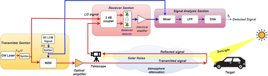
FIGURE 1. Block diagram of the proposed coherent heterodyne-detected FMCW photonic radar system under the influence of atmospheric attenuations and solar background noise (LFM, linear frequency modulated; CW, continuous wave; LO, local oscillator; MZM, Mach–Zehnder modulator; LPF, low-pass filter; OSA, optical spectrum analyzer).
The proposed system is divided into three sections. The first section is the transmitter section, which consists of a narrow linewidth CW laser source whose one part is intensity-modulated by an RF-linear frequency-modulated signal and then transmitted toward the target via free-space links. The other part of the same input CW laser source is employed as a local oscillator signal, which is optically mixed with the signal reflected back from the target using a 3 dB optical coupler and then transferred to the balance photodetector at the receiver section. The detected signal at the output of the balance photodetector is then electrically mixed with the original RF-LFM signal followed by a low-pass filter at the signal processing section in order to obtain a beat signal that determines the target’s range frequency and Doppler frequency.
2.1 Mathematical analysis
In the transmitter section of the proposed setup, the sinusoidal signal is frequency-modulated with a saw-tooth signal to produce the RF-linear frequency-modulated signal, i.e., the radar signal, which is given as follows [24]
where
Similarly, the input CW laser source is given as
where
The CW laser is intensity-modulated by the RF-linear frequency-modulated signal using the Mach–Zehnder modulator operating at a minimum transmission point. This RF-LFM-modulated optical signal is then transmitted toward the target via the free-space link, which is given as [16, 17, 24]
where
After detecting the target, the reflected signal from the target is the time-delayed replica of the transmitted signal with time delay
This time delay
where R represents the range of the target and c is the speed of the light.
Now, in order to achieve the heterodyne coherent detection, the same CW laser source from the transmitter is used as a local oscillator and optically mixed with the reflected signal from the target at the balance photodetector using the 3 dB optical coupler. The output of the 3 dB optical coupler can be expressed as [24]
where
where
The complex output of the photodetector 1 and photodetector 2 is given as
where
Thus, the complex output of the balance photodetector is represented as
After solving, we get
Considering only the real-part output of the balance detector, we get
Now, the output of the balance detector represented in Eq. 11 is electrically mixed with the RF-LFM signal represented in Eq. 1 followed by a low-pass filter to reject the higher frequency component and to obtain the detected signal at the output, which is expressed as [16, 17, 24]
where
2.2 FMCW photonic radar link consideration
In the photonic radar system, generally the maximum distance at which the target can be measured is important; thus, some important factors affecting the maximum range accuracy should be considered such as design consideration for proper target surface diffuse reflection, coherent detector noise, various environmental factors in free-space optic link like atmospheric weather attenuation, and solar background noise [39]. Figure 2 shows the graphical outline representation of some important link budget considerations of the FMCW photonic radar measurement, which should be kept in mind while analyzing the system in order to achieve better ranges.
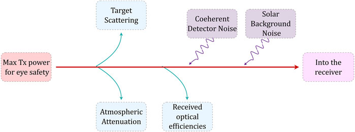
FIGURE 2. Graphical outline representation of some important link budget considerations of the FMCW photonic radar system.
When the RF-LFM-modulated optical signal is transmitted toward the target after striking it, a reflected echo signal retrieves back free-space links, which experience divergence and scattering along with some physical processes in the free-space optical link. Thus, the losses due to these factors can be investigated using the radar equation given in Eq. 15. Various factors affecting the detection range can be estimated using the change in reflected power from the target at the receiver section of the photonic radar system, which is given as [34]
where
where
This reflected signal
where SSI in Wm2nm-1 is the solar spectral irradiance, which is used to quantify the amount of solar irradiance captured by the receiver and its effect on the system performance. The value of SSI has strong dependence on different sky weather conditions and the position of Sun (i.e., zenithal angles) [42]. The zenithal angle
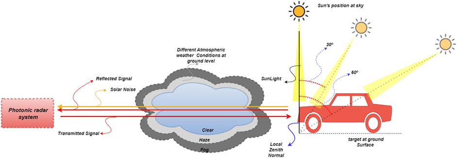
FIGURE 3. Conceptual diagram of the proposed photonic radar system under the influence of various atmospheric weather conditions at the ground level and solar background noise.
Thus, the reflected power from the target with solar noise is given as [34]
When this solar noise-induced reflected signal from the target is beat with the input local oscillator signal using a balance photodetector, optical heterodyning of three input optical fields come into existence for contributing noise, i.e., input laser signal, local oscillator signal, and solar background noise. Since in heterodyning,
a) Thermal noise,
b) Shot noise,
c) New sources of noise (due to solar background noise).
Thermal noise and shot noise are two main sources of detector noise which limit the receiver signal-to-noise ratio of the photonic radar system. Noise spectral density for thermal and shot noise is given as
In Eq. 19,
In FMCW photonic radar system measurement, the DC optical power is dominated by the local oscillator component. Thus,
Thus, the coherent detector limited the SNR of the FMCW photonic radar system, which is given by [24, 39]
Eq. 23 shows that by increasing the local oscillator power
Like detector noise, sunlight also causes several new sources of noise at the system receiver [35, 39]. The shot noise caused by the local oscillator is further increased in magnitude by the solar spectral irradiance; however, due to relatively low intensity of SSI as compared to LO, the effect of solar-induced shot noise is neglected. Second, due to solar spectral irradiance being spread over a few nanometers around the operating wavelength, it mixes with itself generating solar self-mixing noise, also known as solar–solar mixing noise. The solar self-mixing spectral density is given by
where
Thus, the total SNR due to the solar noise-induced coherent detector of the FMCW photonic radar system is given by [35, 39]
3 Simulation setup
The proposed coherent heterodyne-detected FMCW photonic radar system is successfully implemented using MATLAB OptiSystem co-simulation software. In the proposed simulation setup as shown in Figure 1, a CW laser source with wavelength
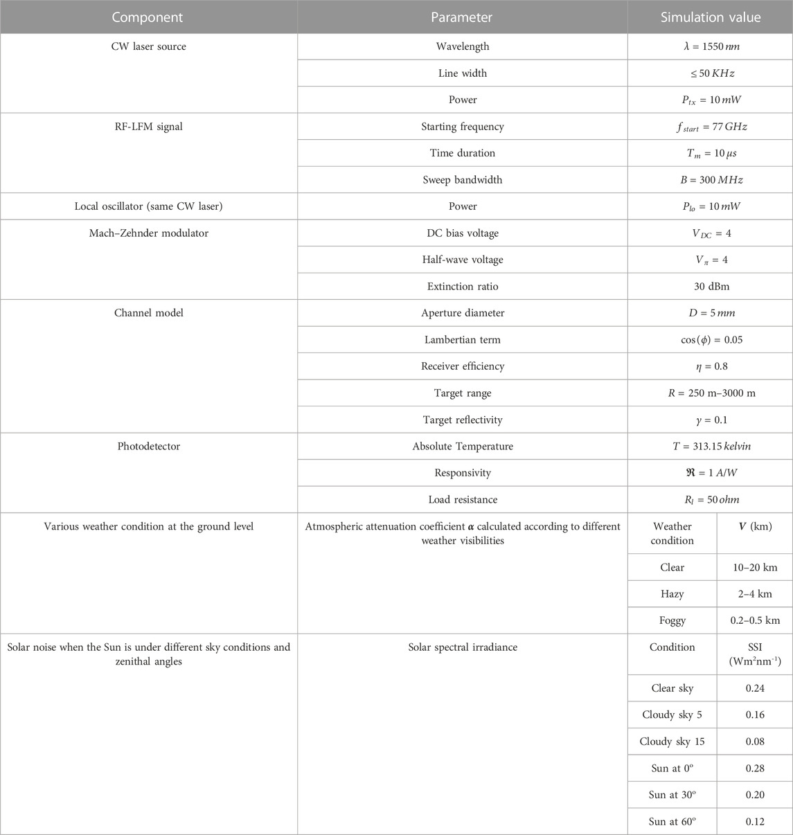
TABLE 1. Simulation parameters of the proposed photonic radar system.
4 Results and discussion
In this section, all-inclusive discussion of results obtained from the proposed photonic radar system is presented. The proposed system is designed to analyze the impact of various atmospheric attenuations and solar background noise on the detection range performance of the system in terms of signal-to-noise ratio. RF-linear frequency-modulated signal with the sweep bandwidth of 300 MHz is used as a radar signal, as shown in Figure 4, and is modulated over a CW laser using the Mach–Zehnder modulator operating at the minimum transmission point, generating first-order single sidebands, which is shown in Figure 5A.
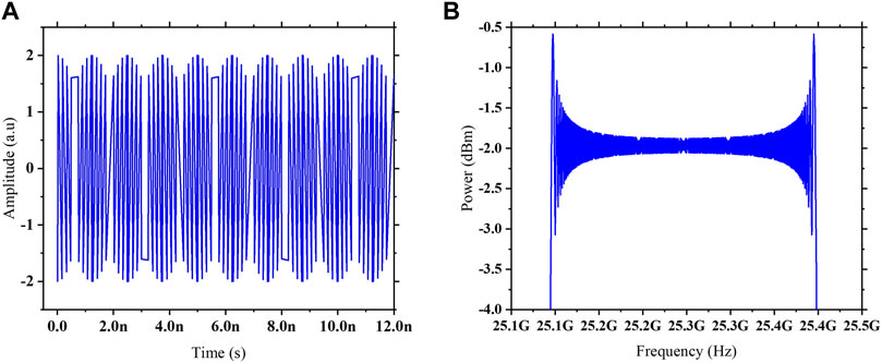
FIGURE 4. Simulated RF-LFM signal waveform representation. (A) Time domain. (B) Frequency domain.
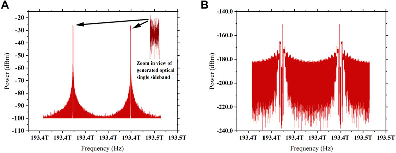
FIGURE 5. (A) Simulated spectrum of generated single sidebands of the optical signal modulated by the RF-LFM signal at the output of the MZM, which is transmitted toward the target. (B) Optical spectrum of the signal reflected back from the target.
This RF-LFM-modulated optical signal is then applied to the transmitting telescope lens and transmitted toward the target at the range distance of 500 m via free-space optic links. The reflected echoes from the target under various environmental factors, as shown in Figure 5B, are captured by the receiving telescope lens. This reflected signal from the target is then combined with the same input laser source via the 3 dB optical coupler and then launched to a balanced photodetector in order to obtain optical heterodyne detection. At the output of the photodetector, the de-chirped detected signal is converted from the optical to electrical signal and then mixed with the original RF-LFM signal to obtain beat signal frequency.
To investigate the effects of various atmospheric weather conditions at the ground level, the peak intensity of the detected signal is first analyzed for clear atmosphere and then compared with hazy and foggy atmosphere. Then, the impact of the solar background noise on the detection range performance is analyzed in terms of signal-to-noise ratio. First, the signal-to-noise ratio variation with the target range under various atmospheric conditions at the ground level is analyzed in the absence of solar noise and then compared under the presence of solar noise in order to evaluate its potential to degrade the system performance. Then, the comparative investigation of detecting range performance when the Sun is under different sky conditions, i.e., clear and cloudy with the optical depth thickness of 5 and 15 and at different zenithal angles, i.e., 0o, 30o, and 60o is conducted in terms of signal-to-noise ratio. Furthermore, the variation in the solar spectral irradiance with the maximum distance achieved, minimum received power, and solar noise-limited SNR is analyzed for different solar noise-dominant regions. At last, the range resolution of the proposed system is examined.
The output spectrum of the detected stationary target located at a distance of 500 m is shown in Figure 6A. In our analysis, the effects of different atmospheric weather conditions such as clear, hazy, and foggy at the ground level on the detected output signal are analyzed. In addition to various atmospheric attenuations, the aforementioned detected signal is also affected by detector noise and solar background noise. When the Sun is at 300 zenithal angle and under the clear sky condition, the stationary target at 500 m is detected at beat frequency
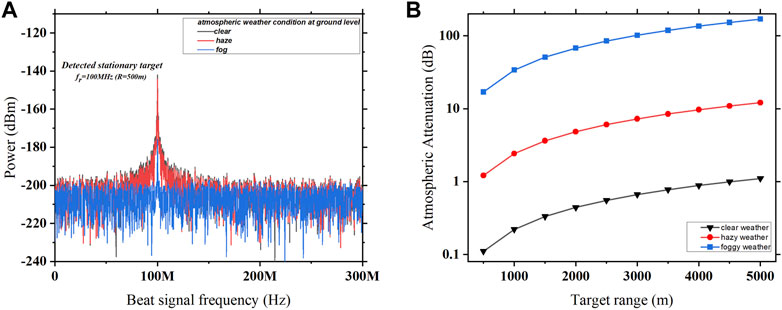
FIGURE 6. (A) Output spectrum of the detected stationary target of the proposed system under different atmospheric weather conditions. (B) Variation in different atmospheric weather attenuations with the increase in the target range.
Figure 6B shows that for clear weather, the atmospheric attenuation at 500 m is 0.11 dB, which is increased to 1.1 dB when reaching 5,000 m. Similarly, for hazy and foggy weather conditions, the value of atmospheric attenuation keeps increasing with the increase in the target range. This indicates that as the distance between the transmitter and receiver increases, the atmospheric attenuation reduces the quality of transmission and effectiveness of free-space optic links. At 500 m for the clear weather condition, the atmospheric attenuation is 0.11 dB, which is increased to 1.21 dB and further to 16.98 dB for hazy and foggy weather conditions. This means that for the same range of the target distance, foggy weather is able to introduce very high atmospheric attenuation of 336 dB/km in the transmission signal when compared to clear and hazy weather with an atmospheric attenuation of 0.2 dB/km and 2.42 dB/km, respectively. Thus, the detected signal experiences higher atmospheric attenuation due to the foggy weather as compared to clear and hazy weather conditions. Furthermore, Eq. 18 shows that there are two attenuation factors with respect to target ranges, i.e., the quadratic term and exponential term. At the lower target ranges, the quadratic term dominates the exponential term and vice versa in case of higher target ranges. This inference also shows (Figure 6B) that since the ordinate of the graph is exponential, the plot tends to be linear at higher target ranges owing to the dominance of the exponential term.
The performance of the coherent heterodyne-detected photonic radar system is analyzed in terms of receiver’s signal-to-noise ratio. Since the overall signal-to-noise ratio of the system depends upon two factors, namely, the effects of different atmospheric attenuations, which degrade the detected signal power, and second the effects of solar spectral irradiance, which give rise to new sources of solar noise at the photodetector, the variation in SNR at different target ranges that extend from 250 m to 3,000 m is measured and compared by taking both considerations into account, as shown in Figure 7. Figure 7A shows that when the atmospheric weather condition is clear at the ground level, the SNR exponentially decreases with the increase in the target range in both conditions, i.e., with and without the influence of solar noise. The SNR measured in the absence of solar noise is 41.26 dB at the 500 m target range, which is degraded to 14.7 dB when affected by solar noise, and maintains a constant difference of 28 dB in SNR throughout the different target distances. In the case of the hazy atmospheric weather condition, the SNR is degrading exponentially at lower target ranges and moving toward linear behavior with higher values of the target range in both conditions, i.e., with and without the influence of solar noise while maintaining a difference in the SNR of 26 dB, as shown in Figure 7B. For foggy weather conditions, the SNR follows linear variation with the increase in the target range in both the conditions, as shown in Figure 7C, with the constant SNR difference of 11 dB.
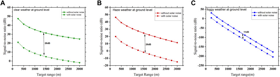
FIGURE 7. Variation in SNR versus target distance for different atmospheric weather conditions. (A) Clear, (B) haze, and (C) fog, with and without the solar noise.
The solar noise power depends upon the Sun’s position at different zenithal angles and Sun under different sky conditions; thus, the solar noise-limited SNR at different target ranges under these conditions are also measured and compared. Figures 8A–C show the signal-to-noise ratio when the atmospheric weather condition at the ground level is clear, hazy, and foggy, respectively, in addition to the influence of solar background noise under different sky conditions, i.e., clear and cloudy with optical depth thicknesses of 5 and 15.
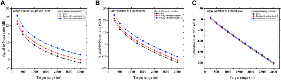
FIGURE 8. Solar noise-limited SNR measured at different target ranges when the Sun is under different sky conditions, and the atmospheric weather condition at the ground level is (A) clear, (B) hazy, and (C) foggy.
Figure 8A shows that when there is a clear atmospheric weather condition at the ground level and Sun is under the clear sky condition, the SNR measured at the target range of 500 m is 14.9 dBm, which is increased to 16.55 dBm and further to 19.55 dBm when the sky condition becomes cloudy with optical depth thicknesses of 5 and 15, respectively. Figure 8B shows that when there is a hazy atmospheric weather condition at the ground level and Sun is at the clear sky condition, the solar noise-limited SNR measured at the target distance of 500 m is 12.59 dBm, which is improved by 2 dBm and 5 dBm when the sky condition is changed to cloudy with optical depth thicknesses of 5 and 15, respectively. Figure 8Cshows that for foggy weather at the ground level and Sun under the clear sky condition, the solar-limited SNR measured at the target distance of 500 m is −18.9 dBm, which is also improved by 2 dBm and 4 dBm when the sky condition becomes cloudy with optical depth thicknesses of 5 and 15, respectively. This improvement in SNR is the result of clouds’ intense radiation scattering and severe radiation extinction as it travels through them and toward the ground, which reduces the power of solar noise. On the other hand, with a clear sky, solar noise takes over since there is less air scattering. SNR is lower in this instance because the solar noise level is higher under a clear sky condition.
Figure 8A shows that when the target range is extending from 500 m to 3,000 m, the solar noise-limited SNR is reducing exponentially from 14.79 dBm to −1.86 dBm when there is clear atmospheric weather at the ground level and Sun is under clear sky conditions. Likewise for hazy weather at the ground level and Sun under the clear sky condition, as shown in Figure 8B, the SNR measured at the 500 m target range is 12.59 dBm, which decreases to −15.06 dBm when reaching the target distance of 3,000 m; it is also observed that the solar noise-limited SNR decreases exponentially for lower range values and moving toward linearity in higher target ranges. In the case of foggy weather, solar-limited SNR decreases in linear variation from −18.9 dBm to −204.315 dBm for the same range of the target distance, as shown in Figure 8C. Since the exponential atmospheric attenuation factor is higher for foggy conditions than that for clear and hazy conditions, under foggy conditions, the exponential term dominates the quadratic term even in lower target ranges and hence exhibits linear characteristics throughout the region.
As discussed in the theory section, under different sky conditions, the solar background noise effect on the photonic radar system also depends on the Sun’s position at different zenithal angles. The position of the Sun during the daytime varies according to different zenithal angles, which determines the value of the solar spectral irradiance resulting in solar noise. The solar noise-limited SNR measurement when the Sun is at different zenithal angles under different atmospheric weather conditions at the ground level is shown in Figures 9A–C.
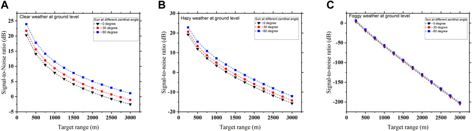
FIGURE 9. Solar noise-limited SNR measured at different target ranges when the Sun is at different zenithal angles, and the atmospheric weather condition at the ground level is (A) clear, (B) hazy, and (C) foggy.
It can be observed that for different zenithal angles of the Sun, the solar noise-limited SNR decreases exponentially with the increase in target range when the atmospheric weather at the ground level is clear and hazy, as shown in Figures 9A, B, and moves toward linearity when the weather at the ground level becomes foggy, as shown in Figure 9C. This is because under clear and hazy weather conditions, atmospheric attenuation is weak as compared to foggy weather, which makes the received signal power high and comparatively higher than the solar noise power; however, in the case of foggy weather condition, the received signal power keeps decreasing and become comparatively equal to solar noise power. Thus, the received signal power is affected by various atmospheric attenuations and is influenced by solar noise according to different positions of the Sun. Figure 9A shows that solar noise-limited SNR is measured when the target range increases from 500 m to 3,000 m and decreases exponentially from 14.12 dBm to −2.53 dBm when there is a clear atmospheric weather condition at the ground level, and the Sun is at 0o zenithal angle. Likewise, for hazy weather at the ground level and the Sun at 0o zenithal angle, as shown in Figure 9B, the SNR measured at the 500 m target range is 11.90 dBm, which decreases to −15.73 dBm when reaching the target distance of 3,000 m; it is also observed that the solar noise-limited SNR decreases exponentially for lower range values and moves toward linearity in higher target ranges. In the case of foggy weather, solar noise-limited SNR decreases in linear variation from −19.6 dBm to −203.52 dBm for the same range of the target distance, as shown in Figure 9C.
Figure 9A shows that for clear weather conditions at the ground level, the solar-limited SNR measured when the Sun is at 0o zenithal angle is 14.1 dBm, which increases to 15.58 dBm and further to 17.79 dBm when the Sun moves to 30o and 60o zenithal angles, respectively. Figure 9B shows that when there is a hazy atmospheric weather condition at the ground level and the Sun is at 0o zenithal angle, the solar noise-limited SNR measured at the target distance of 500 m is 11.9 dBm, which increases by 1.5 dBm and 4 dBm when the Sun moves to 30o and 60o zenithal angles, respectively. Figure 9C shows that for foggy weather at the ground level and when the Sun is at 0o zenithal angle, the solar noise-limited SNR measured at the target distance of 500 m is −19.6 dBm, which also increases by 1 dBm and 3.5 dBm when the Sun moves to 30o and 60o zenithal angles, respectively. This is because when the Sun is at 0o zenithal angle, i.e., during the daytime at noon, the solar noise is maximum and decreases when the Sun reaches 30o and 60o zenithal angles, lowering the effect of solar noise.
Figures 10A–C show the variation in the solar spectral irradiance with the maximum achievable target range, minimum received power, and receiver’s signal-to-noise ratio at different solar noise-dominant regions. There are three possible regimes for the solar-limited SNR, and the dominant effect depends on the value of SSI during the measurement. LO-shot noise is dominated when
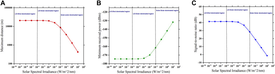
FIGURE 10. Solar spectral irradiance affecting (A) maximum target range, (B) minimum received power, and (C) signal-to-noise ratio at different solar noise-dominant regions.
Now, LO-solar noise is dominated when
Similarly, solar–solar noise is dominated when
Lastly, the range resolution of the proposed photonic radar system is examined. Range resolution is defined as the ability to distinguish between two closely spaced targets and is theoretically given as
According to the aforementioned Eq. 27, for a sweep bandwidth of 300 MHz, the theoretical range resolution is 0.5 m. Thus, in order to examine the range resolution of the proposed system, two target scenarios have been used. Here, target A is at 500 m range and target B is at 501 m, such that they are 1 m apart from each other as shown in Figure 11A. Figure 11A shows that the detected signal peaks of the two targets obtained from numerical simulation overlaps and cannot be distinguished. Furthermore, when these two targets are 3 m apart, there is a partial overlapping, and the peaks cannot be distinguished clearly, as shown in Figure 11B. At last, the range resolution is examined when the two targets are 5 m apart, as shown in Figure 11C. The detected signal peak of targets A and B are distinct and non-touching; hence, it is distinguishable. The results obtained from the numerical simulation suggest that the proposed system can successfully detect multiple targets with the range resolution of 5 m.
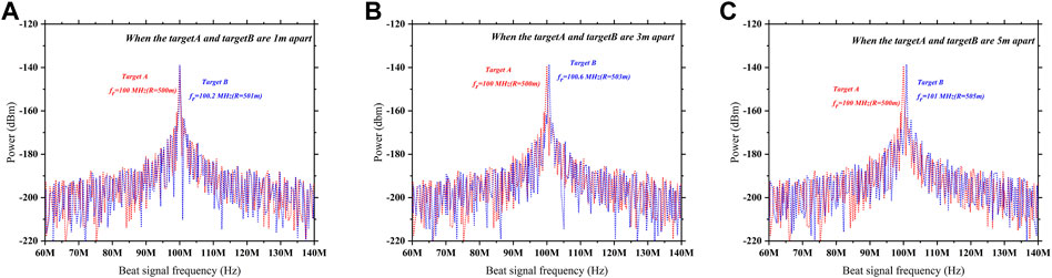
FIGURE 11. Range resolution profile under two target scenario: (A) when target A and target B is 1 m apart; (B) 3 m apart; (C) 5 m apart.
The proposed FMCW photonic radar system is compared with the recent related works reported in the literature, as shown Table 2. In Refs [43, 44], the author has proposed the photonic-based radar system using MLL pulsed laser modulated by an RF radar signal operating at S-band (2–4 GHz) and X-band (4–8 GHz), which can determine range information of the target at a large distance but has limited range resolution. Furthermore, the authors in Refs [45–47] used the FMCW photonic radar system where the linear frequency-modulated signal operating system at Ku-band (12–18 GHz) and K-band (18–27 GHz) is used, which is capable of providing high range resolution and accuracy with the simultaneous range and velocity measurement. However, the system is not investigated under the real environment scenario, which limits its real-time application capabilities. In Refs [30, 48], many others have proposed the FMCW photonic radar system operating at W-band (75–110 GHz), which is widely used for automotive vehicle radar systems and is investigated under adverse weather conditions such as haze, fog, and rain that limit the detection range performance and precision of the system. In addition, various atmospheric attenuations and effects of solar background noise on the photonic radar system have also been reported by some authors in [37, 49]. Along with these published literature works, some commercially available lidar systems are available in the market, which provide single-chip lidar for fast connectivity and improved safety in autonomous mobility as reported in Ref. [50]. Another commercial lidar for the self-driving system is available, which is designed for operating in the bandwidth of 1,550 nm and uses FMCW technology and coherent detection, that allows high-sensitive measurement with a high dynamic range of over 200 m, as reported in [51].
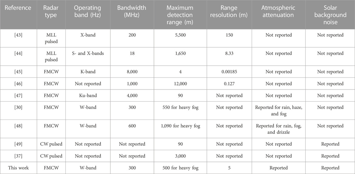
TABLE 2. Comparison of this article with recent related works.
The proposed photonic radar system is designed using practical values and recent technology in the commercial photonic radar system, which makes it more reliable. Furthermore, in comparison to all the aforementioned literature works, our proposed coherent heterodyne-detected FMCW photonic radar system is better as it is examined under various atmospheric attenuations along with the influence of solar background noise. Our system with the range resolution of 5 m achieves the target range of 500 m under clear weather conditions in the presence of solar noise with an acceptable SNR of 14.7 dB, which makes the system robust. However, the proposed work is limited to the simulated environment scenario using OptiSystem–MATLAB co-simulation; there may be some variation in real-time measurement when compared to numerical simulation measurement, but the proposed system can potentially help the researchers in designing the practical photonic radar system, which will allow sensitive measurement with high dynamic ranges. The system finds its application in the field of automotive vehicle radar systems, self-traffic control systems, navigation systems, etc.
5 Conclusion
In this paper, the FMCW photonic radar system using coherent heterodyne detection is proposed. The RF-LFM-modulated optical signal is transmitted toward the target via free-space optic links modeled using the MATLAB–OptiSystem co-simulation platform. The reflected echoes from the target are analyzed under the effect of various atmospheric weather conditions at the ground level and under the influence of solar background noise. The overall performance of the system is analyzed in terms of receiver’s signal-to-noise ratio. The stationary target is successfully detected under different atmospheric weather conditions, which shows that the foggy weather introduces very high atmospheric attenuation as compared to clear and hazy weather. The result shows that to achieve the SNR of 30 dB, the maximum target range extends to 1,500 m when the weather is clear, but in case of hazy and foggy weather, the target range limits only to 1,000 m and 500 m, respectively. In the presence of solar noise, this SNR is reduced from 30 dB to 4.8 dB to achieve 1,500 m under clear weather conditions and further to 4 dB to achieve 1,000 m under hazy weather and −18.94 dB to achieve 500 m under foggy weather conditions , respectively. The observation shows that solar noise can potentially degrade the performance of the photonic radar system, which also depends on the Sun at different positions and sky conditions. Furthermore, the proposed system achieves the range resolution of 5 m at the target range of 500 m under clear weather conditions in the presence of solar noise with an acceptable SNR of 14.7 dB, which makes the system robust. To the best of our knowledge, the proposed setup under the combined effects of atmospheric attenuation and solar noise is analyzed for the first time, and thus the system is reliable, making it suitable for designing practical photonic radar systems for applications in the field of automotive vehicle system, self-traffic control system, and navigation system.
Data availability statement
The raw data supporting the conclusion of this article will be made available by the authors, without undue reservation.
Author contributions
AnK: writing—original manuscript, methodology, simulation design, and analysis; AmK: review, editing, and supervision; GR: substantial contributions to simulation designing and paper writing. All authors contributed to the article and approved the submitted version.
Funding
This work was supported by the Department of Science and Technology (project no. CRG/2021/001176), Ministry of Human Resources and Development, Government of India.
Acknowledgments
The authors would like to thank the Department of Electronics Engineering, Indian Institute of Technology (Indian School of Mines), Dhanbad, Jharkhand, for supporting the research work.
Conflict of interest
The authors declare that the research was conducted in the absence of any commercial or financial relationships that could be construed as a potential conflict of interest.
Publisher’s note
All claims expressed in this article are solely those of the authors and do not necessarily represent those of their affiliated organizations, or those of the publisher, the editors, and the reviewers. Any product that may be evaluated in this article, or claim that may be made by its manufacturer, is not guaranteed or endorsed by the publisher.
References
1. De S, Bazil Raj AA A survey on photonics technologies for radar applications. J Opt (2022) 52:90–119. doi:10.1007/s12596-022-00897-x
3.National weather services (.gov). Radar basics (2022). Available from: https://training.weather.gov/nwstc/NEXRAD/RADAR/Section1-2.html (Accessed November 20, 2022).
4. Kumar A, Gautam A, Priye V Microwave photonic mixer using DP-DDMZM for next generation 5G cellular systems. Fiber Integr Opt (2020) 39(4):149–68. doi:10.1080/01468030.2020.1826068
5. Cox CH, Ackerman EI, “Microwave photonics: Past, present and future,” 2008 IEEE Int Meet Microw Photon jointly held 2008 Asia-Pacific Microw. Photon Conf. MWP2008/APMP2008, 2008. 9–11. doi:10.1109/MWP.2008.4666621
6. Ghelfi P, Laghezza F, Scotti F, Serafino G, Pinna S, Onori D, et al. Photonics in radar systems: RF integration for state-of-the-art functionality. IEEE Microw Mag (2015) 16(8):74–83. doi:10.1109/MMM.2015.2441591
7. Cheng H, Zou X, Lu B, Jiang Y High-resolution range and velocity measurement based on photonic LFM microwave signal generation and detection. IEEE Photon J (2019) 11(1):1–8. doi:10.1109/JPHOT.2018.2888565
8. Pan S, Zhang Y Microwave photonic radars. J Light Technol (2020) 38(19):5450–84. doi:10.1109/JLT.2020.2993166
9. Borowski T, Pasternak M, Pietrasinski J, “The photonic radar: The situation today and the prospects for the future,” (2020) 2020, 52. doi:10.1117/12.2565721
10. Col L, Kassotakis I Modern radar techniques for air surveillance & defense. Greece: Scienpress Ltd (2014).
11. Zhang C, Sun X, Zhang R, Liu Y, “Simulation and assessment of solar background noise for spaceborne lidar,”Appl Opt (2018) 57(31):9471. doi:10.1364/ao.57.009471
12. Li S, Cui Z, Ye X, Feng J, Yang Y, He Z, et al. Chip-based microwave-photonic radar for high-resolution imaging. Laser Photon Rev (2020) 14(10):1900239–6. doi:10.1002/lpor.201900239
13. Serafino G, Amato F, Maresca S, Lembo L, Ghelfi P, Bogoni A Photonic approach for on-board and ground radars in automotive applications. IET Radar, Sonar Navig (2018) 12(10):1179–86. doi:10.1049/iet-rsn.2018.5017
14.Fhwa An investigation of the use of global positioning system (GPS) technology and its augmentations within state and local transportation departments. Technology (2000).
15. Piatek S, A photonic guide to the autonomous vehicle market. In: Laser focus world (2017). p. 28–31.
16. Chaudhary S, Wuttisittikulkij L, Saadi M, Sharma A, Al Otaibi S, Nebhen J, et al. Coherent detection-based photonic radar for autonomous vehicles under diverse weather conditions. PLoS One (2021) 16(11):e0259438–13. doi:10.1371/journal.pone.0259438
17. Chaudhary S, Sharma A, Khichar S, Tang X, Wei X, Wuttisittikulkij L High resolution-based coherent photonic radar sensor for multiple target detections. J Sens Actuator Networks (2022) 11:49–3. doi:10.3390/jsan11030049
18. Serafino G, Scotti F, Lembo L, Hussain B, Porzi C, Malacarne A, et al. Toward a new generation of radar systems based on microwave photonic technologies. J Light Technol (2019) 37(2):643–50. doi:10.1109/JLT.2019.2894224
19. Baxter JA, Merced DA, Costinett DJ, Tolbert LM, Ozpineci B, “Review of electrical architectures and power requirements for automated vehicles,” IEEE Transp Electrif Conf Expo ITEC (2018) 2018. 102–7. doi:10.1109/ITEC.2018.8449961
21. Adany P, Allen C, Hui R Chirped lidar using simplified homodyne detection. J Light Technol (2009) 27(16):3351–7. doi:10.1109/JLT.2009.2016220
22. Diego P, Farzin A, Larry P, Bruce B, George L, Manuel R, “Linear FMCW laser radar for precision range and vector velocity measurements diego pierrottet,” MRS Online Proc Libr (2019) 107. 1–9.
23. Sharma A, Chaudhary S, Malhotra J, Parnianifard A, Kumar S, Wuttisittikulkij L Impact of bandwidth on range resolution of multiple targets using photonic radar. IEEE Access (2022) 10:47618–27. doi:10.1109/ACCESS.2022.3171255
24. Elghandour AH, Ren CD Modeling and comparative study of various detection techniques for FMCW LIDAR using optisystem. Int Symp Photoelectron Detect Imaging 2013 Laser Sens Imaging Appl (2013) 8905:890529. doi:10.1117/12.2034878
25. Ali M, Ali A, Mohammed MA Effect of atmospheric attenuation on laser communications for visible and infrared wavelengths (2013).
26. Banday Y, Rather GM, Rasool Begh G Effect of atmospheric absorption on millimetre wave frequencies for 5G cellular networks. IET Commun (2019) 13(3):265–70. doi:10.1049/iet-com.2018.5044
27. Scotti F, Laghezza F, Ghelfi P, Bogoni A Multi-band software-defined coherent radar based on a single photonic transceiver. IEEE Trans Microw Theor Tech. (2015) 63(2):546–52. doi:10.1109/TMTT.2014.2386877
28. Scotti F, Bogoni A, Laghezza F, Onori D, “Tracking of a naval target with a dual-band photonic-based coherent radar system,” in IEEE Radar Conf RadarConf (2016) doi:10.1109/RADAR.2016.7485221
29. Ju Y, Jin Y, Lee J, “Design and implementation of a 24 GHz FMCW radar system for automotive applications,” 2014 Int Radar Conf Radar (2014) 3. 29–32. doi:10.1109/RADAR.2014.7060385
30. Sharma V, Sergeyev S, Range detection assessment of photonic radar under adverse weather perceptions. Opt Commun 472. (2020). doi:10.1016/j.optcom.2020.125891
31. Mabrouk M, Abdullah HH, Hussein K, Hussein AH A novel algorithm for moving/fixed target discrimination in 77 GHz automotive radars. 2019 Photon Electromagn. Res. Symp. - Fall, PIERS - Fall 2019 - Proc. (2019) 128–33. doi:10.1109/PIERS-Fall48861.2019.9021394
32. Sharma A, Chaudhary S, Malhotra J, Parnianifard A, Wuttisittikulkij L Measurement of target range and Doppler shift by incorporating PDM-enabled FMCW-based photonic radar. Optik (Stuttg). (2022) 262:169191. doi:10.1016/j.ijleo.2022.169191
33. Sharma A, Chaudhary S, Malhotra J, Khichar S, Wuttisittikulkij L Photonic sensor for multiple targets detection under adverse weather conditions in autonomous vehicles. J Sens Actuator Networks (2022) 11:60–4. doi:10.3390/jsan11040060
34. Of F, Engineering E Department of radio electronics snímání atmosféry lidarem: APLIKACE NA DETEKCI CO 2 Bc. Czechia: D AVID CÍSAŘ (2011).
35. Leeb WR Degradation of signal to noise ratio in optical free space data links due to background illumination. Appl Opt (1989) 28(16):3443. doi:10.1364/ao.28.003443
36. Hamza T, Khalighi M-A, Bourennane S, Léon P, Opderbecke J Investigation of solar noise impact on the performance of underwater wireless optical communication links. Opt Express (2016) 24(22):25832. doi:10.1364/oe.24.025832
37. Kim DL, Kong HB, Lee ST Effects of solar noise on the detection range performance of a laser spot tracker. Opt Eng (2021) 60(3):037102. doi:10.1117/1.OE.60.3.037102
38. Lee JW, Choi JY, Hyun YJ, Han SK Solar background noise mitigation using the orbital angular momentum mode in vertical FSO downlink transmissions. Opt Express (2021) 29(21):33312. doi:10.1364/oe.438550
39. Sandborn P FMCW lidar: Scaling to the chip-level and improving phase-noise-limited performance. Berkeley: University of California (2019).
40. Islam N, Al N, Bhuiyan S, “Effect of O perating W avelengths and D ifferent W eather C onditions on P erformance of P oint -T O -P oint F ree space,” (2016) 8(2). 63–75.
41. Awan MS, Brandl P, Leitgeb E, Nadeem F, Plank T, Capsoni C, “Results of an optical wireless ground link experiment in continental fog and dry snow conditions,”Int Conf Telecommun Contel (2009) 45–9.
42. Wald L BASICS in solar radiation at earth surface -revised version to cite this version: Hal id: hal-02164311,” no (2019). July.
43. Ghelfi P, Laghezza F, Scotti F, Serafino G, Capria A, Pinna S, et al. A fully photonics-based coherent radar system. Nature (2014) 507(7492):341–5. doi:10.1038/nature13078
44. Brandão TH, Scotti F, Filgueiras HRD, Alves AADC, Onori D, Melo S, et al. Coherent dual-band radar system based on a unique antenna and a photonics-based transceiver. IET Radar, Sonar Navig (2019) 13(4):505–11. doi:10.1049/iet-rsn.2018.5046
45. Ye X, Zhang F, Yang Y, Zhu D, Pan S Photonics-based high-resolution 3D inverse synthetic aperture radar imaging. IEEE Access (2019) 7:79503–9. doi:10.1109/ACCESS.2019.2921802
46. Fang S, Li G, Zhang F, Han B, Hong W A novel scheme for processing FMCW-ladar data acquired with low sampling rate. Geo-spatial Inf Sci (2022) 25(3):489–99. doi:10.1080/10095020.2021.2023662
47. Ding Y, Li M, Wu H, Dong W Photonic-based radar for distance and velocity measurement with multiformat waveforms. Appl Opt (2023) 62(2):463. doi:10.1364/ao.478397
48. Sharma A, Chaudhary S, Malhotra J, Saadi M, Al Otaibi S, Nebhen J, et al. A cost-effective photonic radar under adverse weather conditions for autonomous vehicles by incorporating a frequency-modulated direct detection scheme. Front Phys (2021) 9:1–9. doi:10.3389/fphy.2021.747598
49. Nguyen TT, Cheng CH, Liu DG, Le MH Improvement of accuracy and precision of the LiDAR system working in high background light conditions. Electron (2022) 11(1):45–18. doi:10.3390/electronics11010045
50.Analog Photonics. Optical phased array lidar (2023). Available from: Analogphotonics.com/product/phased-array-lidar/ (Accessed March 20, 2023).
51.The Aurora Team. Aurora to acquire blackmore, industry-leading lidar company (2019). Available from: https://blog.aurora.tech/progress/aurora-to-acquire-blackmore-industry-leading-lidar (Accessed March 20, 2023).
Keywords: photonic radar, linear frequency-modulated continuous wave, Mach–Zehnder modulator, solar spectral irradiance, automotive vehicle radar
Citation: Kumari A, Kumar A and Reddy GST (2023) Performance analysis of the coherent FMCW photonic radar system under the influence of solar noise. Front. Phys. 11:1215160. doi: 10.3389/fphy.2023.1215160
Received: 01 May 2023; Accepted: 16 May 2023;
Published: 01 June 2023.
Edited by:
Santosh Kumar, Liaocheng University, ChinaReviewed by:
Monu Nath Baitha, Yonsei University, Republic of KoreaSushank Chaudhary, Chulalongkorn University, Thailand
Rui Min, Beijing Normal University, China
Copyright © 2023 Kumari, Kumar and Reddy. This is an open-access article distributed under the terms of the Creative Commons Attribution License (CC BY). The use, distribution or reproduction in other forums is permitted, provided the original author(s) and the copyright owner(s) are credited and that the original publication in this journal is cited, in accordance with accepted academic practice. No use, distribution or reproduction is permitted which does not comply with these terms.
*Correspondence: Annapurna Kumari, anupurna1992@gmail.com