 I. Mardor1,2*
 H. Wilsenach2,3
 T. Dickel4,3I. Eliyahu1M. Friedman5T. Y. Hirsh1A. Kreisel1
 O. Sharon1M. Tessler1S. Vaintraub1
 F. V. Uhlemann3
- 1Soreq Nuclear Research Center, Yavne, Israel
- 2School of Physics and Astronomy, Tel Aviv University, Tel Aviv, Israel
- 3II. Physikalisches Institut, Justus-Liebig-Universität Gießen, Gießen, Germany
- 4GSI Helmholtzzentrum für Schwerionenforschung GmbH, Darmstadt, Germany
- 5Racah Institute of Physics, The Hebrew University of Jerusalem, Jerusalem, Israel
The Soreq Applied Research Accelerator Facility (SARAF) will be based on a 40 MeV, 5 mA CW (continuous wave) proton/deuteron superconducting linear accelerator, currently under construction at Soreq Nuclear Research Center in Yavne, Israel. It is planned to commence operation during 2025. Experiments at SARAF could provide data on high-energy deuteron- and neutron-induced cross-sections, yields and radiation damage, which are invaluable for the design and operation of the International Fusion Materials Irradiation Facility-DEMO-Oriented NEutron Source (IFMIF-DONES), and fusion technology in general. Pulsed beams (∼1 nsec) of variable energy deuterons will irradiate a lithium target and generate pulsed neutron beams with energy up to ∼55 MeV, which will be used to measure energy-dependent neutron-induced differential cross-sections, utilizing time of flight techniques. Impinging continuous wave (CW) 40 MeV deuteron beams on a unique gallium-indium (GaIn) liquid-jet target, will generate a neutron rate of more than 1 × 10¹⁵ n/sec, with energies up to ∼45 MeV. We plan to use this high rate to measure integral neutron-induced reaction yields of all channels simultaneously, employing an original novel method that will identify the reaction-produced nuclei via accurate mass measurement. The neutron-energy dependence of the yields could be deduced by combining measurements at various deuteron energies. The measured cross-sections and yields at SARAF may predict the activation characteristics of construction materials of IFMIF-DONES and future fusion reactors. The deuteron beams will also be used directly to measure cross-sections via in-beam and offline methods. The high neutron and deuteron rates will extend SARAF’s reach to rare materials. The deuteron beam power density on the liquid GaIn target will be 100 kW/cm2 (similar to IFMIF-DONES) on a 2 cm2 spot. The resulting neutron flux on small secondary samples will be in the 1013 n/cm2/s level, only an order of magnitude less than IFMIF-DONES. Therefore, SARAF may serve as a pilot facility for fusion-related radiation damage studies, providing important information towards the design of IFMIF-DONES.
1 Introduction
Research and development of fusion technology is an ongoing world-wide effort that aims to design and build power plants based on nuclear fusion reactors. The underlying energy generation process will be d-t fusion, which generates neutrons at an energy of 14 MeV. At the demonstration fusion power plant (DEMO) [1], the neutron flux at the reactor chamber first wall is expected to be 1014 n/cm2/sec [2]. Therefore, thorough understanding of neutron-induced activation and radiation damage in construction materials is a paramount requirement for the reliable and safe operation of fusion power plants. To fulfill this need, the International Fusion Materials Irradiation Facility-DEMO-Oriented NEutron Source (IFMIF-DONES) [2] is being planned. It will be a neutron source with a broad energy distribution similar to that of d-t fusion, by irradiation of Li with 40 MeV deuterons [3]. The high deuteron current of IFMIF-DONES, 125 mA, will result in a neutron flux similar to that expected in DEMO [4].
The reliable and safe operation of IFMIF-DONES, a deuteron accelerator and neutron source of unparalleled power and performance, is a major scientific and engineering challenge on its own. Its detailed design requires high-quality cross-section data for reactions induced by neutrons and deuterons in the energy range up to ∼50 MeV. The expected deuteron- and neutron-induced activation along the accelerator and deuteron beamlines up to the Li target is crucial for defining the facilities beam-loss characteristics and predicting the residual radiation dose distributions in its vicinity.
A combination of neutron-induced yields and cross-sections comprises the “damage cross-section” [5], which is the main ingredient in theoretically evaluated neutron-induced radiation damage values [5]. Furthermore, long-lived activation products may lead to significant long-term waste disposal and radiation damage. Since nuclear data on high-energy neutron- and deuteron-induced cross-sections is scarce, it has become customary to use the evaluated nuclear data library TENDL [6] that is based on the output of the TALYS nuclear model code system [7]. However, TALYS uses nuclear models with parameters that rely on experimental data, so it has limited reliability for predicting unmeasured cross-sections for arbitrary nuclei in broad energy ranges. Even for iron, a widespread structural material in nuclear applications, recent benchmark studies of neutron-induced reactions showed discrepancies in TENDL [8]. Therefore, nuclear cross-section measurements of high-energy neutron- and deuteron-induced reactions on the structural materials of IFMIF-DONES and fusion reactors are highly needed.
The Soreq Applied Research Accelerator Facility (SARAF) [9, 10], under construction at Soreq Nuclear Research Center (SNRC) [11] in Yavne, Israel, is based on a superconducting linear accelerator of protons and deuterons up to 35 and 40 MeV respectively, at a current up to 5 mA continuous wave (CW). Its cutting-edge specifications (Table 1) will enable deuteron reaction studies up to 40 MeV, and unique irradiation targets [12–14] will make SARAF a world-competitive source of thermal to high-energy neutrons, reaching up to 45 and 55 MeV using liquid gallium-indium and solid lithium targets, respectively. Due to the novelty of SARAF’s accelerator and target technology, it was divided into two phases. SARAF-I had low energy (a few MeV) and high current (up to 2 mA CW protons) to test and characterize the required technologies and was used from 2010 to 2019 for research that utilized its exceptional beams [9, 10]. The full project (SARAF-II, Table 1) was approved in 2015 and is planned to be operational during 2025.
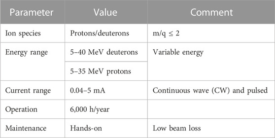
TABLE 1. SARAF main beam specifications.
In this article, we elaborate our plans for deuteron- and neutron-induced research at SARAF. We show that it could be used to provide invaluable experimental data on cross-sections and yields that are needed for IFMIF-DONES and fusion reactors, which are currently evaluated only theoretically. We further show that the high-power density on the liquid GaIn target may generate locally a very high neutron flux, which could be used for radiation damage measurements on small samples, serving as a pilot for IFMIF-DONES.
2 Neutron and deuteron experiments at SARAF
SARAF will be based on a linear accelerator installed downstream of an electron cyclotron resonance (ECR) ion source, a low energy beam transport line (LEBT) and a 4-rod radio-frequency quadrupole (RFQ) pre-accelerator. The accelerator will include a 5-m-long medium energy beam transport line (MEBT) and four superconducting modules housing a total of 27 half-wave resonators (HWRs) with a frequency of 176 MHz. The design and construction of the SARAF accelerator are described in Refs. [15, 16]. In Figure 1 we show the layout of the SARAF accelerator, its high energy beam lines (HEBTs) and four irradiation target stations, which are described in Ref. [10]. Here we focus on the irradiation stations and experimental methods that are relevant for fusion technology research.
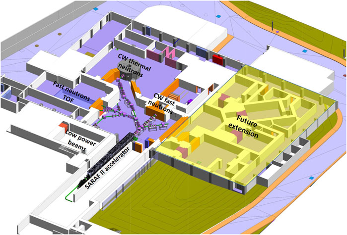
FIGURE 1. The layout of the SARAF accelerator, beam lines and irradiation stations as planned to be installed in the constructed target hall. The four irradiation areas are described in Ref. [10]. The yellow-highlighted part is a future extension that is not built yet. Reprinted with permission from [10].
2.1 Neutron-induced reactions
To fulfill the potential neutron rates from the high proton and deuteron currents of SARAF, advanced targets that serve as converters to neutrons are required. These targets must withstand a significant part (or even all) of the high power induced by the SARAF ion beams. The SARAF team has demonstrated and is developing several target types that are suitable for this challenge, which are described below in the context of their various applications.
2.1.1 Neutron in-beam differential cross-sections
Energy dependent differential cross-sections of neutron-induced reactions will be obtained by pulsed neutron beams. They will be produced by bombarding single bunches of deuterons on light ion targets such as Li, Be or B, thick enough to stop the ion beam. This maximizes the neutron rate, albeit producing a continuous energy spectrum that is resolved by time of flight (TOF) methods.
These experiments will take place in the fast neutron TOF hall (Figure 1) that has an 18-m neutron flight path. The SARAF 176 MHz ion beam structure comprises bunches with a width less than ∼1 ns separated by ∼5.6 nsec. To avoid overlap of slow neutrons from successive bunches (down to ∼0.1 MeV), the SARAF bunch rate should be reduced to below ∼250 kHz. This will be achieved by a fast beam chopper that acts as a single bunch selector, which has been demonstrated recently [17]. The highest single-bunch selection frequency achieved so far is 220 kHz [17], accelerating one out of 800 ion bunches. The achieved time resolution for the SARAF single-bunch selector is 0.75 ns FWHM [17]. Together with an estimated flight path uncertainty of 2–3 cm, the expected neutron energy resolution after an 18-m flight path is slightly above 0.2 MeV FWHM for 30 MeV neutrons.
Single-bunch selection at 220 kHz corresponds to an average current on target of 6–7 μA (average power of 250 W for 40 MeV deuterons). Based on measured neutron yields [3], such a pulsed deuteron beam will produce ∼1012 neutrons/sec [10] when impinging on a thick Li target (25 mm). An upgrade of the SARAF single-bunch selector to a frequency of up to 1 MHz is underway [17], which will enable an increase of the neutron rate by a factor of about 5. To avoid neutrons from successive bunches down to 0.1 MeV, the flight path should be reduced to 4 m, worsening the energy resolution to slightly below 0.8 MeV FWHM for 30 MeV neutrons. The flight path and bunch selection frequency can be interplayed in order to obtain optimal neutron rate or energy resolution, depending on the specific application.
Generating neutrons at a 1 MHz single-bunch selection will require light ion targets (preferably Li or Be) that are able to sustain power in the kW range. Such targets have been demonstrated at the Neutron for Science (NFS) facility at GANIL [18] and additional targets for the kW range are under development at SARAF [19, 20].
In Figure 2 we show the expected neutron fluxes at flight paths of 18 and 4 m, at maximal beam repetition rates that avoid overlap between successive bunches, in comparison to other pulsed neutron facilities. Clearly, SARAF will be a competitive facility for high-energy neutron studies from 0.1 MeV and higher, especially above 10 MeV, the relevant range for measuring neutron-induced reactions for fusion technology.
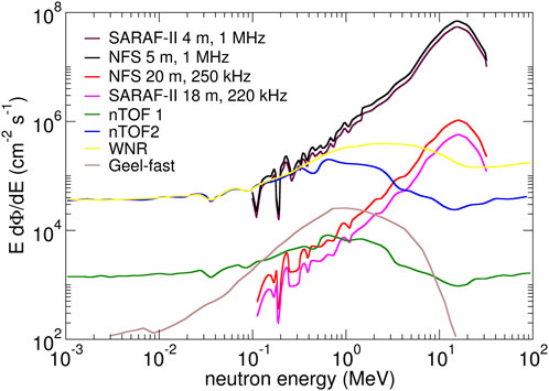
FIGURE 2. Expected neutron fluxes at the SARAF fast neutrons TOF hall, at flight paths of 18 and 4 m, with maximal beam repetition rates that avoid overlap from successive bunches. Neutron fluxes from other facilities (NFS, n-TOF, Geel, WNR) are adapted from [21]. Figure is adapted with permission from [17].
In parallel to increasing the single-bunch selection frequency, we are presently developing a “pre-buncher” upstream of the single-bunch selector. This device will focus the beam longitudinally before the fast-chopping procedure, thus significantly increasing the number of beam particles in a single bunch, consequently increasing SARAF’s pulsed neutron rate for any single-bunch selection frequency, beyond the rates given in Figure 2. The high neutron flux of SARAF could be utilized to measure reaction cross-sections on rare and radioactive targets that are available only in minute sizes.
Detection systems for in-beam differential cross-sections for neutron-induced reactions at SARAF are presently under design. They will be inspired by planned and existing systems at similar facilities. Examples include MEDLEY, for double-differential neutron-induced light-ion production cross-sections via silicon detectors and CsI scintillators [22], and GAINS and GRAPhEME, for inelastic reactions (n,n’γ) and (n,xnγ) via high-purity Ge (HPGe) gamma detectors [23].
2.1.2 Neutron activation measurements
Activation measurements of nuclear cross-sections will be performed by irradiating a target and identifying and counting the reaction products offline. These measurements are useful for obtaining the cross-sections of reaction channels that create specific nuclei. The usual identification method is gamma spectroscopy. If the reaction products decay to the ground state (no gammas) they can be identified by low level counting (LLC) techniques of Auger electrons. If they are very long-lived or are stable, one can use atom counting techniques such as accelerator mass spectrometry (AMS) and Atom Trap Trace Analysis (ATTA). Applications of the above methods for activation measurements induced by a Maxwellian spectrum of epi-thermal neutrons at SARAF are reviewed in [24].
Time of flight methods for neutron energy measurements can be used to extract the neutron spectrum impinging on the target, but are not relevant for activation measurements, due to their offline nature. Energy-dependent activation measurements for high-energy neutrons are achieved by bombarding high-energy protons on thin Li or Be targets (1.5 or 0.5 mm, respectively). The main proton-induced neutron-production reactions on these targets are (p,n) charge exchange, and with a thin target, the minimal proton energy straggling results in a quasi-mono-energetic neutron beam. For protons of tens of MeV, the quasi-mono-energetic peak constitutes about 50% of the total neutron rate. The rest of the neutrons are distributed in a relatively flat tail down to a few MeV, but with Be targets there are also one or more satellite peaks below the main one, due to excited states in the reaction’s outgoing nucleus.
Quasi-mono-energetic neutron beams were demonstrated for the energy range 20–90 MeV at CYRIC in Tohuku University, Japan, with a peak flux of about 3.5 × 10⁸ neutrons/sr/MeV/μC and a FWHM width of 3–4 MeV at 65 MeV from a 1.65 mm thick Li target [25]. At NFS, utilizing a 31.9 MeV proton beam on a 1.5 mm thick Li target, a peak flux of about 1.4 × 10⁹ neutrons/sr/MeV/μC and a FWHM width of 1–2 MeV at 30 MeV from a 1.5 mm thick Li target was obtained [18]. The integral flux above 27 MeV in this measurement was (1.77 ± 0.21)× 109 neutrons/sr/μC [18].
The maximal neutron flux at SARAF will be limited by the proton beam power that can be sustained by Li or Be thin targets. Based on [19, 20], a reasonable baseline assumption is 1 kW, which corresponds to a maximal average proton current of about 35 μA at 30 MeV. Based on NFS’s results [18], this leads to a neutron flux at this energy of about 6 × 10¹⁰ neutrons/sr/sec in a quasi-mono-energetic peak around 30 MeV.
2.1.3 Simultaneous yields of reaction products
2.1.3.1 Method overview
As described in [10], we plan to impinge the CW fast neutrons from the SARAF GaIn beam dump (Figure 1) on thin natural actinide targets to produce high amounts of neutron-rich isotopes via neutron-induced fission. The fission products will be thermalized in a gas-filled stopping cell, separated, and transferred to a multiple-reflection time-of-flight mass spectrometer (MR-TOF-MS) [26]. The design of this SARaf exOtic Nuclide fAcility (SARONA) [27] is based on the FRagment Separator (FRS) Ion Catcher at GSI [28], with a cryogenic stopping cell (CSC) similar to that planned for the Facility for Antiproton and Ion Research (FAIR) [29].
It is possible to replace the thin actinide targets in SARONA with thin targets of any material of interest. In these cases, we will use this instrument to simultaneously record all neutron-induced reactions on that material. The cross-section for each reaction channel will be obtained by simultaneous identification and counting of all recoil nuclei via accurate mass measurement with the MR-TOF-MS. Thus, all reaction channels will be measured simultaneously with the same method on the same instrument. This original method is universal, since all elements are extracted from the CSC, with extraction and mass measurement times in the order of a few tens of milliseconds. The detection efficiency of recoil nuclei may be element-dependent, but this efficiency can be evaluated for each relevant element via offline calibration with a well-known spontaneous fission source such as 252Cf, as demonstrated in [30]. The method is suitable for measuring the “damage cross-section” of relevant fusion technology materials, a combination of neutron-induced yields and cross-sections, which is the main ingredient in theoretically evaluated neutron-induced radiation damage [5].
2.1.3.2 Simulations of specific reactions
As an example, we describe the implementation of this technique to neutron-induced reactions on iron, a main construction material for IFMIF-DONES and DEMO. In Figure 3 we show the simulated neutron flux per energy on a target that is placed 9 cm away from the neutron source, when irradiated by 5 mA of 40 MeV deuterons. Simulations were performed with FLUKA [31] for 40 MeV deuterons impinging a 5 mm thick GaIn target. The normalization to 5 mA was performed by the total neutron yield from thick GaIn when irradiated by 40 MeV deuterons, (2.70 ± 0.24)× 1014 n/sec/mA, recently measured at Forschungszentrum Julich GmbH [32]. We consider 9 cm to be a realistic distance due to the neutron source and CSC instrumentation.
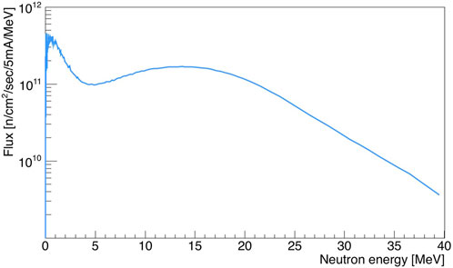
FIGURE 3. Simulated neutron energy spectrum obtained from FLUKA [30]. The plot shows the average neutron flux as a function of energy, for a 5 × 5 cm2 sample that is placed 9 cm downstream of the GaIn target, when irradiating it by 40 MeV deuterons with a current of 5 mA CW.
In Figure 4 we show evaluated cross-sections of selected reaction channels that open up when irradiating iron with neutrons at energies up to 20 MeV, extracted from the JEFF 3.3 database [33]. One can see that in almost all cases, each channel results in a different recoil nucleus, so counting them will lead to cross-sections of these channels unambiguously. There are a few cases where the same recoil nucleus can refer to two different reactions, e.g., (n,np) and (n,d). However, due to the d binding energy the thresholds for these two reactions will be significantly different, so these channels can be separated.
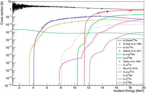
FIGURE 4. Evaluated cross-sections of several neutron-induced reaction channels on iron. Evaluations are from JEFF 3.3 [33]. Experimental data is shown for four reactions. Additional channels have been measured at various neutron energies and for other reaction channels, the evaluations are purely theoretical. Experimental data are taken from [34–37].
A schematic diagram of the measurement setup is shown in Figure 5. It includes the spatial distributions of the ranges of six selected reaction products from the irradiation of 56Fe by 14 MeV neutrons. These events were generated by GEANT4 [38], release 11.01.02, using the physics list JEFF/NeutronHP. In Figure 6, we show the simulated recoil kinetic energy versus scattering angle for two reactions on a 5 nm thin 56Fe target, 56Fe (n,α)53Cr and 56Fe (n,p)56Mn, right after the reaction. The blue points refer to those isotopes that escape forward from the target, and the orange points to those that do not. The low recoil energies translate to a typical range of tens of nm of the recoil nuclei inside the sample target, which limits the effective areal density of relevant targets to about 0.1 mg/cm2. For (n,α), the α energy is high enough to induce backward recoil motion when the reaction is peripheral. For (n,p), also the peripheral reaction induces forward recoil motion, but at a much lower energy. The broadening is due to the difference in sharing of the target excitation energy between the outgoing reaction product and emitted gammas in each reaction.
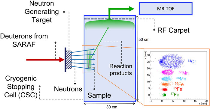
FIGURE 5. A schematic drawing of the instrument for simultaneous measurements of neutron-induced reactions on given materials. The neutrons from SARAF impinge on a sample, and reaction products exit the sample and penetrate a few mm into the buffer gas of the CSC. The penetration in the buffer gas depends on the reaction product mass and energy, which are different for each case. The inset shows the ranges of six possible reaction products from a 56Fe sample. Each dot in the inset represents the end point of a reaction product in a specific event from a thin 1 × 1 cm2 sample. The plot was generated via our GEANT4 simulations that are described in the text. The reaction products are extracted via the RF carpet to a MR-TOF mass spectrometer for unambiguous identification.
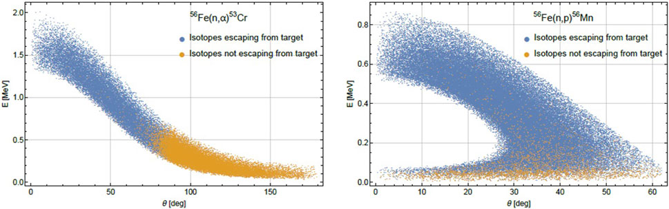
FIGURE 6. Kinetic energy versus angle of the recoil nuclei for 56Fe (n,α)53Cr (left) and 56Fe (n,p)56Mn (right), as simulated by GEANT4. 14 MeV neutrons impinge normally on a 5 nm thin 56Fe target. The blue points refer to those isotopes that escape forward from the target, and the orange points to those that do not.
In Figure 7 left we show the GEANT4-simulated rates of measured reaction products for selected neutron-induced reactions on iron (56Fe), as a function of the iron target thickness. The rates are per 1010 neutrons/sec, with energy of 14 MeV, incident normal to the target (parallel beam). The rates include the escape efficiency from the target (Figure 7 right), and the expected ∼10% efficiency of SARONA [9]. Based on Figure 3, the rate of neutrons with an energy between 13.5 and 14.5 MeV, on a 1 cm2 thin iron target, located 9 cm from the neutron source, will be ∼1.7 × 10¹¹ neutrons/sec. From Figure 7 left, the detection rate of the 6 selected isotopes in the figure, for a 100 nm thick target, will vary from 0.1 to 100 isotopes/sec. The detection will be performed via the MR-TOF-MS of SARONA [9], where the background rates under specific mass peaks are expected to be extremely low. For example, in a recent experiment at the FRS Ion Catcher at GSI [39], for a ∼3-h measurement, the background contribution was merely ∼1.7 ± 0.2 events. Namely, a rate of ∼1.6 × 10⁻⁴ background events per second. Thus, for a rate of 0.1 isotopes/sec, we will obtain statistically significant events (3σ level) within 100 s. We consider here only Poisson variations, which are the main contribution to the uncertainty of event counts within a mass peak. This will enable relatively quick measurement of all processes that comprise the damage cross-section [5], which is required for radiation damage calculations.
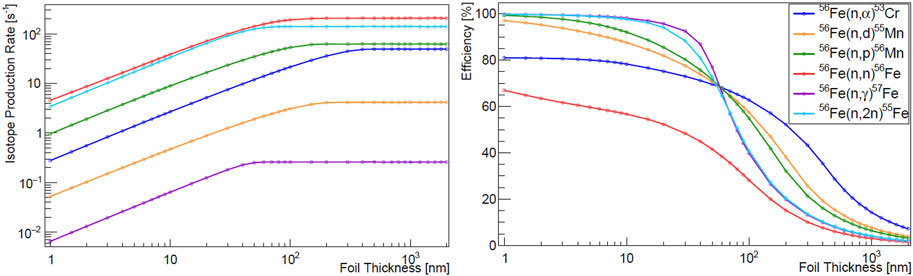
FIGURE 7. Left–Simulated production rate for 6 isotopes listed in the legend of the right panel, which result when impinging 1010 14 MeV neutrons per second on a thin iron target, as a function of the iron target thickness. The rates include the production cross-sections depicted in Figure 4, and the escape efficiency of the isotopes, depicted in the right panel of this figure. We assume a parallel beam of neutrons that imping normal to the target surface.
During SARONA’s commissioning phase, it is planned to be installed outside the neutron source room and receive a reduced flux of neutrons through a hole that will be drilled in the 2.5-m-thick concrete wall of the neutron source chamber. This will reduce the neutron flux by a factor of about 104. Nevertheless, given the rates described in the previous paragraph, cross-sections of a significant number of reaction channels will be measurable within a reasonable time.
A small-solid-angle target (∼1 cm2 area at ∼9–10 cm from the neutron source) will be beneficial for these measurements, since then the assumption of parallel neutron beam will be reasonable, and no further corrections will be needed for the produced isotope ranges inside the target. Furthermore, varying the target thickness and comparing the rates to our simulation’s predictions may help the de-convolution process for extracting the production cross-sections.
According to our simulations, the recoil nuclei that escape from the thin actinide target will have ranges of a few mm in the helium buffer gas, at a maximal rate of ∼103 nuclei per second (Figure 7, left). This ion density does not pose a risk of enhanced space charge that might limit nuclei extraction from the CSC, since alpha-recoil sources of higher rates and smaller range are being regularly used at the FRS Ion Catcher [28].
2.1.3.3 Coarse neutron energy dependence
The rates in Figure 7 left are given for a specific neutron energy (14 MeV), which is the energy of interest for fusion technology studies. However, the neutron spectrum from the thick liquid GaIn target will be very wide, as depicted in Figure 3. This means that for some channels, the obtained cross-sections will be an integral over the entire neutron energy range.
A more detailed energy dependence of the cross-sections may be obtained by performing the experiment in two consecutive deuteron energies and subtracting the obtained yields of the measured nuclei. The subtraction results will be equivalent to a measurement on a thin target whose width will reduce the deuteron energy by the difference between the two runs. To estimate how the subtracted spectra will look like, we used GEANT4 Version 10.7 [High Precision (HP), NDL database] to simulate the neutron production via deuteron irradiation of a thick GaIn target at two energies, 15 and 16 MeV. As a cross check of the simulation, we also simulated 16 MeV deuterons on a thin target (53 microns, the GaIn that is required for 16 MeV deuterons to lose 1 MeV) and saw that the observed neutron spectrum is statistically consistent with the subtracted 16 and 15 MeV spectra.
Deuteron induced reactions consist of two main components–compound nucleus (CN) reactions where the neutrons emerge from the target nuclei, and deuteron breakup (DB), where the neutrons emerge from the projectile deuterons. The energy distribution of the CN neutrons is similar for 15 and 16 MeV. To obtain a qualitative handle on the DB and CN contributions, for the thin target simulation (sensitive only to deuterons between 16 and 15 MeV) we counted the number of different reaction channels. We observed that the (d,n) channel (resulting mostly from DB) comprises ∼29% of the reactions. The (d,2n) channel is the most abundant in this energy range (∼49%) and another plentiful channel is (d,np), with ∼20%. Three-neutron emission (d,3n) happens in only 1% of the events. No events with a higher number of neutrons were observed.
We performed the GEANT4 simulations with 109 incident deuterons. This is six orders of magnitude below the requirement for a 5-mA beam but is the highest number possible within a reasonable time on a multi-core cluster. This relatively low number generated significant statistical fluctuations in the subtracted spectra, which are merely an artifact of the simulation, and do not represent the expected statistical uncertainty in the future experiments at SARAF. To display the expected spectra in the experiments, we interpolated the simulation results with a polynomial to obtain smooth trends. We then scaled the trends up to a 5-mA deuteron beam and added the expected statistical fluctuations at that high rate. The resultant spectra are shown in Figure 8. These spectra are of forward peaked (opening angle of 60°) neutrons from irradiation of a thick GaIn target by 5-mA beams of 15 and 16 MeV deuterons. One observes that in the 16 MeV irradiation, a significant number of neutrons is added in the high-energy region but in addition, low-energy neutrons are added as well in the entire neutron energy spectrum.
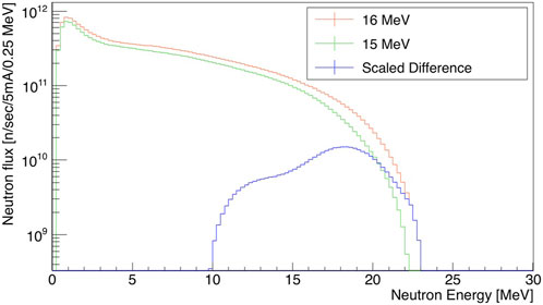
FIGURE 8. GEANT4 simulated spectra of forward neutrons (into an opening angle of 60°) from 16 to 15 MeV deuteron irradiations of a thick GaIn target, at a current of 5 mA (red and green, respectively). Also shown is the subtraction of the two spectra (blue), where the 15 MeV spectrum is scaled by a factor of 1.25 in order to “cancel out” the low energy part and obtain a spectrum of high-energy neutrons. The plots include uncertainty symbols, but in this scale, they are much smaller than the lines thicknesses. These plots are scaled up by six orders of magnitude with respect to the GEANT4 simulation results. See text for details.
The extended range of the 16 MeV deuterons in the target (w.r.t. 15 MeV deuterons) yields an overall higher number of neutrons. The DB neutrons are mainly a result of the (d,n) channel, so those from 16 MeV deuterons are expected to have energies higher by ∼1 MeV w.r.t. 15 MeV deuterons. Their contribution is observed in Figure 8. In order to “cancel out” the low-energy neutrons contribution and to enhance the DB neutrons, prior to subtracting the spectra we scale the 15 MeV spectrum by the obtained overall ratio that is observed for the lower-energy neutrons (for this case, 1.25). The subtracted spectrum is also shown in Figure 8.
Due to the variety of CN reaction channels, the energetic width of the subtracted spectrum comes out to be ∼6–7 MeV FWHM, larger than the 1 MeV difference between the deuteron irradiation energies. Furthermore, the location of the wide peak is ∼5–6 MeV higher than the deuteron energies, due to the positive Q-values of the dominant (d,n) reactions.
Note that the peak bins in the subtracted spectrum are in the range of 1010 neutrons, which are a result of subtracting original spectra bins with an order of 1011 neutrons. Since the statistical fluctuations of the original spectra bins are of order 106, the subtracted spectrum is statistically significant.
It is important to emphasize that Figure 8 is a result of a model dependent GEANT4 simulation, since there is no neutron energy and angular distribution data from deuteron irradiations of Ga or In. We present it in order to visualize the concept of spectrum subtraction for obtaining cross-sections from high-energy neutrons via a thick target. We plan to measure the neutron energy distributions in SARAF, at several deuteron energies up to 40 MeV, which will increase the reliability of cross-section measurements with thick targets and continuous neutron beams.
2.2 Deuteron-induced reactions
SARAF’s variable beam energy (5–40 MeV) makes it an excellent candidate for measuring cross-sections of reactions induced by high energy deuterons. In fixed energy cyclotrons deuteron energy is controlled by degraders that are prone to energy straggling. At the SARAF linear accelerator the energy is set by tuning its acceleration cavities, which results in an energy accuracy of tens of keV throughout its energy range.
For studying rare deuteron induced reactions, or reactions on small, rare, or radioactive samples, special irradiation targets must be used. Encapsulated liquid and foil composite targets were developed at SARAF, where the liquid [9] or the foil [40] can be the target material, and the backing behind the liquid is cooled by liquid gallium-indium jet impingement. A cooling capacity of 8.4 kW/cm2 was demonstrated for this type of target [40]. At 40 MeV, this implies a deuteron irradiation current of 0.21 mA/cm2.
2.2.1 Activation measurements
Deuteron induced activation measurements are performed in the exact same manner as described in Section 2.1.2 for neutron-induced activation. Such measurements were performed at SARAF with deuteron energy in the few MeV range, with an energy accuracy of 50 keV on Cu isotopes [41] and 150 keV on Co and V isotopes [42]. In another experiment, accurate measurements at SARAF (50–70 keV) up to deuteron energy of 5 MeV were combined with measurements from 5.5 MeV up 20 MeV (accuracy of 200–700 keV) that were performed with the cyclotron at NPI-Rez [43] to investigate the (d,p) cross-section of 23Na. This knowledge and experience will be utilized for activation measurements of deuteron induced cross-sections at energies up to 40 MeV, which are needed for the design and operation of IFMIF-DONES.
2.2.2 (d,xn) in-beam measurements
Pulsed deuteron beams, as described in Section 2.1.1, may be used to measure double-differential cross-sections of (d,xn) reactions. The TOF hall (Figure 1) may be used for measuring the emitted neutrons’ energy distributions via the time-of-flight method. With an array of neutron detectors surrounding the target one can perform coincidence measurements to distinguish between (d, n), (d, 2n), and (d, 3n) reactions, and with germanium detectors one can measure the emitted prompt gammas. The germanium detector will be placed in a location and with shielding, to avoid radiation induced damage.
2.3 Neutron-induced radiation damage
The deuteron beam power density on the liquid GaIn target will be 100 kW/cm2 (similar to IFMIF-DONES [2]) on a 2 cm2 spot. The simulated neutron flux as a function of distance from the GaIn liquid target, when irradiated by 5 mA of 40 MeV deuterons, is shown in Figure 9. The flux in Figure 9 is the average one over a 5 × 5 cm2 target in the forward direction. The simulated data was generated by FLUKA. In order to utilize the neutron flux from the GaIn target in the most efficient way, it is preferable to place the sample of interest as close as possible to the neutron source, i.e., on the backplate behind the liquid GaIn flow. This is inspired by an idea to do so for IFMIF-DONES [44]. Based on Figure 9, the neutron flux on the target’s back plate will be 2–3 × 10¹³ n/cm2/sec.
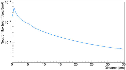
FIGURE 9. The FLUKA simulated neutron flux (average over a 5 × 5 cm2 target in the forward direction) as a function of distance from the GaIn liquid target, when irradiated by 5 mA of 40 MeV deuterons. In this simulation, the GaIn liquid target is placed at Distance = 1 cm.
This means that for a small sample placed in front of the GaIn target at SARAF, the neutron flux will be only an order of magnitude less than that expected at the High Flux Test Module (HFTM) of IFMIF-DONES [4]. Therefore, it may be possible to perform pilot experiments and feasibility studies of high-energy neutron-induced damage on small samples of various materials at SARAF. A possible placement of the irradiation sample on the GaIn target back plate is depicted in Figure 10.
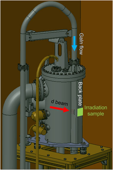
FIGURE 10. CAD drawing of SARAF’s liquid GaIn target. A possible location of the irradiation sample (light green patch) on the target’s back plate is indicated.
In addition to comparing overall fluxes between SARAF and IFMIF-DONES, it is important to compare the neutron energies, since the interest for fusion technology is in the high energy realm. The neutron angular distribution and energy spectrum of GaIn due to irradiation of 40 MeV deuterons have not been measured. However, such measurements have been performed for Fe and Ta [45]. 85% of the atoms of the GaIn mixture in the liquid target are of Ga, the atomic number of Ga is slightly higher than that of Fe (31 and 26, respectively), and the Q-value of the dominant (d,n) reaction channel for Ga is slightly higher than for Fe (∼6.3 MeV for 69Ga, ∼3.8 MeV for 56Fe). Therefore, a comparison between the Li and Fe experimental distributions may be indicative to the comparison between Li and GaIn.
Such a comparison is shown in Figure 11, for neutrons that are emitted forward onto an opening angle of 60°. One can see that the ratio between the relevant energy regions of the Li and Fe spectra (10–20 MeV) is about an order of magnitude, consistent with the forward flux difference that we estimate between IFMIF-DONES and SARAF. Figure 11 further includes the GEANT4 results for 40 MeV deuteron irradiation on a thick GaIn target. One can see that indeed, the data for Fe is quite similar to that of the simulated GaIn results, raising the confidence in the usage of Fe as a proxy for GaIn.
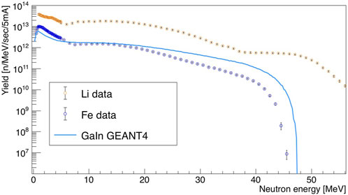
FIGURE 11. The neutron energy spectrum in an opening angle of 60° from thick Li [3] and thick Fe [44] targets (experimental data) and GaIn (GEANT4 simulation result), when irradiated by 5 mA of 40 MeV deuterons. The different end point energies are due to the different Q-values of the dominant (d,n) channels (∼3.8 MeV for 56Fe, ∼6.3 MeV for 69Ga, ∼15.0 MeV for 7Li).
3 Summary and outlook
Within a few years, SARAF will be one of the world’s leading high-energy neutron sources, up to 1015 CW n/sec from a thick liquid GaIn target, and up to 1012 pulsed n/sec from thin light targets (e.g., Li and Be), at energies up to ∼45 and ∼55 MeV, respectively. SARAF will further provide deuteron beams with variable energy from 5 to 40 MeV, with CW or pulsed currents up to 5 mA. These properties will enable unprecedented measurements of deuteron and neutron-induced cross-sections up to 40 and ∼55 MeV, which are very important for fusion technology, but existing experimental data for them is scarce and sparse.
We will utilize SARAF’s deuteron and neutron beams for cross-section measurements with both standard and novel techniques that were presented in the above Sections. We will provide new experimental data that will enable to compile more reliable values of activation profiles and the “damage cross-sections” for the construction materials of IFMIF-DONES and the future demonstration fusion power plant, DEMO.
The neutron flux at a small region near the thick liquid GaIn target will be only an order of magnitude less than that of IFMIF-DONES. We therefore propose that SARAF could be used as a pilot facility for IFMIF-DONES, performing feasibility studies and demonstrations of irradiation of small samples at the world’s highest available high-energy neutron flux.
Data availability statement
The raw data supporting the conclusion of this article will be made available by the authors, without undue reservation.
Author contributions
All authors listed have made a substantial, direct, and intellectual contribution to the work and approved it for publication.
Acknowledgments
The authors thank Prof. Masayuki Hagiwara (Osaka University) for providing the data that enabled the quantitative comparison of neutron spectra from the irradiation of Fe and Li by 40 MeV deuterons.
Conflict of interest
The authors declare that the research was conducted in the absence of any commercial or financial relationships that could be construed as a potential conflict of interest.
Publisher’s note
All claims expressed in this article are solely those of the authors and do not necessarily represent those of their affiliated organizations, or those of the publisher, the editors and the reviewers. Any product that may be evaluated in this article, or claim that may be made by its manufacturer, is not guaranteed or endorsed by the publisher.
References
1. Federici G, Biel W, Gilbert MR, Kemp R, Taylor N, Wenninger R. European DEMO design strategy and consequences for materials. Nucl Fusion (2017) 57:092002. doi:10.1088/1741-4326/57/9/092002
2. Bernardi D, Ibarra A, Arbeiter F, Arranz F, Cappelli M, Cara P, et al. The IFMIF-DONES project: Design status and main achievements within the EUROfusion FP8 work programme. J Fusion Energ (2022) 41:24. doi:10.1007/s10894-022-00337-5
3. Hagiwara M, Itoga T, Kawata N, Hirabayashi N, Oishi T, Yamauchi T, et al. Measurement of neutron emission spectra in Li(d, xn) reaction with thick and thin targets for 40 MeV deuterons. Fus Sci Technol (2005) 48:1320–8. doi:10.13182/FST05-A1081
4. Arbeiter F, Diegele E, Fischer U, Garcia A, Ibarra A, Molla J, et al. Planned material irradiation capabilities of IFMIF-DONES. Nucl Mater Energ (2018) 16:245–8. doi:10.1016/j.nme.2018.05.026
5. Chen S, Bernard D. Recommendation for computing neutron irradiation damage from evaluated nuclear data. J Nucl Mater (2022) 562:153610. doi:10.1016/j.jnucmat.2022.153610
6. Koning AJ, Rochman D, Sublet J-C, Dzysiuk N, Fleming M, van der Marck S. Tendl: Complete nuclear data library for innovative nuclear science and technology. Nucl Data Sheets (2019) 155:1–55. doi:10.1016/j.nds.2019.01.002
7. Koning AJ, Rochman D. Modern nuclear data evaluation with the TALYS code system. Nucl Data Sheets (2012) 113:2841–934. doi:10.1016/j.nds.2012.11.002
8. Raffuzzi V, Sublet JC, Jouanne C, Koning A, Rochman D. An iron evaluation story: From TALYS model parameters to validation on the ASPIS benchmark with the Monte Carlo code TRIPOLI-4. In: Proceedings of the International Conference on Physics of Reactors 2022 (PHYSOR 2022); May 2022; Pittsburgh, PA, USA (2022).
9. Mardor I, Aviv O, Avrigeanu M, Berkovits D, Dahan A, Dickel T, et al. The Soreq applied research accelerator facility (SARAF): Overview, research programs and future plans. Eur Phys J A (2018) 54:91. doi:10.1140/epja/i2018-12526-2
10. Mardor I. A new probe to the high-intensity frontier: Soreq applied research accelerator facility (SARAF). Nucl Phys News (2022) 32(4):5–11. doi:10.1080/10619127.2022.2100154
11. Soreq Nuclear Research Center,2022 https://www.gov.il/en/departments/nuclear-research-center/govil-landing-page [Accessed December 27, 2022]
12. Halfon S, Arenshtam A, Kijel D, Paul M, Weissman L, Aviv O, et al. Note: Proton irradiation at kilowatt-power and neutron production from a free-surface liquid-lithium target. Rev Scientific Instr (2014) 85:056105. doi:10.1063/1.4878627
13. Eliyahu I, Vaintraub S, Mardor I, Arenshtam A, Shvero E, Reinfeld E, et al. High power beam dump and neutron sources for SARAF phase II. In: International Meeting of the Union for Compact Accelerator-driven Neutron Sources (UCANS-8); July 2019; Paris, France (2019).
14. Eliyahu I, Berkovic G, Vaintraub S, Zilberman S, Goldberger N, Dadon M, et al. Optical Measurements of the thickness of the Gallium Indium free surface jet for the SARAF beam dump and neutron source. Nucl Instr Meth A (2023) 1053:168320. doi:10.1016/j.nima.2023.168320
15. Pichoff N, Bazin N, Chirpaz-Cerbat D, Cubizolles R, Dumas J, Duperrier R, et al. The SARAF-linac project 2017 status. In: Proceedings of the 8th International Particle Accelerator Conference (IPAC2017); May 2017; Copenhagen, Denmark (2017).
16. Pichoff N, Duperrier R, Ferrand G, Gastineau B, Gougnaud F, Jacquemet M, et al. The SARAF-linac project 2019 status. In: Proceedings of Proceedings of the 10th International Particle Accelerator Conference (IPAC2019); May 2019; Melbourne, Australia (2019).
17. Kaizer B, Shor A, Zchut T, Weissman L, Perry A, Kreisel A, et al. Upgrade of SARAF fast beam chopper and its applications in Phase I and Phase II of SARAF linac. J Instrumentation (2022) 17:P11019. doi:10.1088/1748-0221/17/11/P11019
18. Ledoux X, Foy JC, Ducret JE, Frelin AM, Ramos D, Mrazek J, et al. First beams at neutrons for science. Eur Phys J A (2021) 57:257. doi:10.1140/epja/s10050-021-00565-x
19. Hirsh TY, Berkovits D, Hass M, Jardin P, Pichard A, Rappaport ML, et al. Towards an intense radioactive 8Li beam at SARAF Phase I. J Phys Conf Ser (2012) 337:012010. doi:10.1088/1742-6596/337/1/012010
20. Hirshfeld H, Silverman I, Arenshtam A, Kijel D, Nagler A. High heat flux cooling of accelerator targets with micro-channels. Nucl Instr Meth A (2006) 562:903–5. doi:10.1016/j.nima.2006.02.104
21. Ledoux X, Aiche M, Avrigeanu M, Avrigeanu V, Audouin L, Balanzat E, et al. The neutrons for science facility at SPIRAL-2. Nucl Data Sheets (2014) 119:353–6. doi:10.1016/j.nds.2014.08.097
22. Dangtip S, Atac A, Bergenwall B, Blomgren J, Elmgren K, Johansson C, et al. A facility for measurements of nuclear cross-sections for fast neutron cancer therapy. Nucl Instr Meth A (2000) 452:484–504. doi:10.1016/S0168-9002(00)00455-1
23. Kerveno M, Bacquias A, Borcea C, Dessagne P, Henning G, Mihailescu LC, et al. From $\gamma$ emissions to (n,xn) cross sections of interest: The role of GAINS and GRAPhEME in nuclear reaction modeling. Eur Phys J A (2015) 51:167. doi:10.1140/epja/i2015-15167-y
24. Paul M, Tessler M, Friedman M, Halfon S, Palchan T, Weissman L, et al. Reactions along the astrophysical s-process path and prospects for neutron radiotherapy with the liquid-lithium target (LiLiT) at the Soreq applied research accelerator facility (SARAF). Eur Phys J A (2019) 55:44. doi:10.1140/epja/i2019-12723-5
25. Baba M, Okamura H, Hagiwara M, Itoga T, Kamada S, Yahagi Y, et al. Installation and application of an intense 7Li(p,n) neutron source for 20–90 MeV region. Radiat Prot Dosimetry (2007) 126:13–7. doi:10.1093/rpd/ncm005
26. Dickel T, Plaß WR, Becker A, Czok U, Geissel H, Haettner E, et al. A high-performance multiple-reflection time-of-flight mass spectrometer and isobar separator for the research with exotic nuclei. Nucl Instr Meth A (2015) 777:172–88. doi:10.1016/j.nima.2014.12.094
27. Paul M, Tessler M, Friedman M, Halfon S, Weissman L. The liquid-lithium target at the Soreq applied research accelerator facility. Eur Phys J A (2022) 58:207. doi:10.1140/epja/s10050-022-00863-y
28. Plaß WR, Dickel T, Purushothaman S, Dendooven P, Geissel H, Ebert J, et al. The FRS Ion Catcher – a facility for high-precision experiments with stopped projectile and fission fragments. Nucl Instr Meth B (2013) 317:457–62. doi:10.1016/j.nimb.2013.07.063
29. Dickel T, Plaß WR, Geissel H, Heiße F, Miskun I, Purushothman S, et al. Conceptional design of a novel next-generation cryogenic stopping cell for the Low-Energy Branch of the Super-FRS. Nucl Instr Meth B (2016) 376:216–20. doi:10.1016/j.nimb.2016.01.015
30. Waschitz Y, Amanbayev D, Spataru A, Mardor I, Dickel T, Cohen EO, et al. Independent isotopic fission yields of 252Cf spontaneous fission via mass measurements at the FRS Ion Catcher. EPJ Web of Conferences (2023) 284:04005. doi:10.1051/epjconf/202328404005
31. Böhlen TT, Cerutti F, Chin MPW, Fassò A, Ferrari A, Ortega PG, et al. The FLUKA code: Developments and challenges for high energy and medical applications. Nucl Data Sheets (2014) 120:211–4. doi:10.1016/j.nds.2014.07.049
32. Kreisel A, Eliyahu I, Vaintraub S, Tessler M, Horin I, Goldberger N, et al. Neutron and isotope production yield from Proton and Deuteron beams in the 20-45 MeV range on thick liquid Gallium-Indium and Lithium targets. Eur Phys J A (2023) 59:185. doi:10.1140/epja/s10050-023-01056-x
33. Plompen AJM, Cabellos O, De Saint Jean C, Fleming M, Algora A, Angelone M, et al. The joint evaluated fission and fusion nuclear data library, JEFF-3.3. Eur Phys J A (2020) 56:181. doi:10.1140/epja/s10050-020-00141-9
34. El-Kadi SM, Nelson CE, Purser FO, Walter RL, Beyerle A, Gould CR, et al. Elastic and inelastic scattering of neutrons from 54,56Fe and 63,65Cu: (I). Measurements from 8 to 14 MeV and a spherical optical model analysis. Nucl Phys A (1982) 390:509–40. doi:10.1016/0375-9474(82)90281-0
35. Wallner A, Buczak K, Lederer C, Vonach H, Faestermann T, Korschinek G, et al. Production of long-lived radionuclides 10Be, 14C, 53Mn, 55Fe, 59Ni and 202gPb in a fusion environment. J Korean Phys Soc (2011) 59(2):1378–81. doi:10.3938/jkps.59.1378
36. Santry DC, Butler JP. Excitation Curves for the Reactions Fe56(n,p)Mn56 and Co59(n, α)Mn56. Can Jour. Phys. (1964) 42:1030–6. doi:10.1139/p64-096
37. Bai H, Jiang H, Lu Y, Cui Z, Chen J, Zhang G, et al. 56,54Fe(n,α)53,51Cr cross-sections in the MeV region. Phys Rev C (2019) 99:024619. doi:10.1103/PhysRevC.99.024619
38. Allison J, Amako K, Apostolakis J, Arce P, Asai M, Aso T, et al. Recent developments in GEANT4. Nucl Instr Meth A (2016) 835:186–225. doi:10.1016/j.nima.2016.06.125
39. Mollaebrahimi A, Hornung C, Dickel T, Amanbayev D, Kripko-Koncz G, Plass WR, et al. Studying Gamow-Teller transitions and the assignment of isomeric and ground states at N=50. Phys Lett B (2023) 839:137833. doi:10.1016/j.physletb.2023.137833
40. Silverman I, Lavie E, Arenshtam A, Kijel D, Vaknin D, Veinguer M, et al. Production of Palladium-103 (103Pd) from a thin rhodium foil target – improved cooling concept. Nucl Instr Meth B (2007) 261:747–50. doi:10.1016/j.nimb.2007.03.058
41. Weissman L, Kreisel A, Hirsh TY, Aviv O, Berkovits D, Girshevitz O, et al. Accurate measurements of the 63Cu(d,p)64Cu and natCu(d,x)65Zn cross-sections in the 2.77–5.62MeV energy rangex)65Zn cross-sections in the 2.77–5.62 MeV energy range. Nucl Instr Meth B (2015) 342:7–12. doi:10.1016/j.nimb.2014.09.002
42. Kreisel A, Weissman L, Cohen A, Hirsh T, Shor A, Aviv O, et al. Measurements of 59Co(d,p)60m,gCo, 51V(d,p)52V, and natV(d, xn)51Cr cross-sections in the 2.7–5.4-MeV energy range. Phys Rev C (2019) 99:034611. doi:10.1103/PhysRevC.99.034611
43. Hirsh TY, Kreisel A, Mrazek J, Weissman L, Eisen Y, Stefanik M, et al. Accurate measurement of the 23Na(d,p)24Na cross-section in the 1.7–20 MeV energy range. Nucl Instr Meth B (2015) 362:29–33. doi:10.1016/j.nimb.2015.09.015
44. Qiu Y, Arbeiter F, Bernardi D, Frisoni M, Gordeev S, Hernández R, et al. Potential use of IFMIF-DONES target back-plate for material specimens. J Nucl Eng (2022) 3:385–97. doi:10.3390/jne3040025
Keywords: fusion, neutrons, deuterons, cross-sections, radiation damage, SARAF
Citation: Mardor I, Wilsenach H, Dickel T, Eliyahu I, Friedman M, Hirsh TY, Kreisel A, Sharon O, Tessler M, Vaintraub S and Uhlemann FV (2023) Opportunities for high-energy neutron- and deuteron-induced measurements for fusion technology at the Soreq applied research accelerator facility (SARAF). Front. Phys. 11:1248191. doi: 10.3389/fphy.2023.1248191
Received: 26 June 2023; Accepted: 18 September 2023;
Published: 29 September 2023.
Edited by:
Ivan Alexander Kodeli, United Kingdom Atomic Energy Authority, United KingdomReviewed by:
Francesco Giovanni Celiberto, Bruno Kessler Foundation (FBK), ItalyEugenia Naselli, Laboratori Nazionali del Sud (INFN), Italy
Copyright © 2023 Mardor, Wilsenach, Dickel, Eliyahu, Friedman, Hirsh, Kreisel, Sharon, Tessler, Vaintraub and Uhlemann. This is an open-access article distributed under the terms of the Creative Commons Attribution License (CC BY). The use, distribution or reproduction in other forums is permitted, provided the original author(s) and the copyright owner(s) are credited and that the original publication in this journal is cited, in accordance with accepted academic practice. No use, distribution or reproduction is permitted which does not comply with these terms.
*Correspondence: I. Mardor, bWFyZG9yQHRhdWV4LnRhdS5hYy5pbA==