 Long Jin1,2*
 Yang Xiang3
- 1Shiyan Key Laboratory of Quantum Information and Precision Optics, School of Mathematics, Physics and Optoelectronic Engineering, Hubei University of Automotive Technology, Shiyan, China
- 2Hubei Key Laboratory of Energy Storage and Power Battery, Collaborative Innovation Center for Optoelectronic Technology, Hubei University of Automotive Technology, Shiyan, China
- 3Department of Information Engineering, Xizang Minzu University, Xianyang, China
The transformation regulation of the radial finite Airy–Gaussian beam array (FAiGBA) in uniaxial crystals orthogonal to the optical axis has been explored analytically and numerically under the paraxial approximation. The analytical evolution solution of this beam array in the x- and y-directions has been derived, respectively. The intensity distribution and side view of FAiGBA propagating in three types of uniaxial crystals have been demonstrated in several instances. Furthermore, particular attention has been devoted to the linear effect when this beam array transmits through the electro-optic crystal. The influence of non-paraxial longitudinal component and temperature on FAiGBA evolution characteristics has also been examined to verify the validity of the paraxial mechanism of this beam array propagating in uniaxial crystals. It is anticipated that these research findings will contribute to the advancement of FAiGBA applications in micro- and nano-control, optical fiber communication, optical trapping, and manipulation fields.
1 Introduction
Researchers have attracted wide interest in the generation and application of finite energy Airy beams (FAiBs) due to their non-diffraction, self-accelerating, and self-healing characteristics [1–3], with which some gratifying results have been gained in particle manipulation, curved plasma channel excitation, photo-bullets, surface plasmons, focus control, and micromachining [4–9]. However, the FAiB intensity and density become very smaller over a long transmission distance because of the beam diffraction and atmospheric turbulence. In order to overcome these obstacles, considerable attention has been switched to finite Airy–Gaussian beam array (FAiGBA) [10, 11] because the intensity of the self-focusing FAiGBA remains almost constant during propagation, but its peak intensity can suddenly increase by several orders of magnitude when approaching the focus plane (where the beam array’s self-focusing intensity is greatest).
On the other hand, attention has also been devoted to uniaxial crystals [12] and nonlinear media [13] in which a variety of waves transit. As a typical anisotropic medium, a uniaxial crystal plays an important role in the regulation of light field by using its linearly electro-optical effect (Pockels effect) [14], which can achieve high-speed electro-optic response at modulation rates up to tens of GHz. Therefore, the evolution of various types of beam transmission in uniaxial crystals has been widely studied by researchers for a long time. It is the most interesting effect that crystals can change the polarization of input waves. For example, scientists have found that left-handed circularly polarized (LHCP) light can generate vortex light with topological charge number 2 when propagating along the optical axis of uniaxial crystals, the method of which has become an important supplement for generating vortex beams [15]. There are a number of crystals whose refractive indices are affected by the applied electric field (or electric voltage), and the size of the refractive index is also related to the direction, resulting in a linearly electro-optical effect. Electro-optical crystals, like potassium dihydrogen phosphate [16] and lithium niobate [17], are widely used in the field of optoelectronic technology as electro-optical modulators, electro-optical switches, electro-optical logics, tunable filters, and quantum devices, achieving excellent performance [18–21].
FAiBs [22] and their derived waves, such as Airy–Gaussian beam [23, 24], Airy–Gaussian vortex beam [25, 26], chirped Airy vortex beam [27], Airy–Hermite–Gaussian beam [28], cosh-Airy beam [29], and radially polarized first-order chirped Airy–Gaussian beam [30], passing through the uniaxial crystal in paraxial approximation and beyond have been inspected in the last 10 years. To deal with the bad axial symmetric problem of a single Airy beam, the circular Airy beam [31] and circular Airy vortex beam [32] via uniaxial crystals have been discussed not long ago as well. FAiGBA evolution in the isotropic space [33] and Kolmogorov atmospheric turbulence [34] has been examined by our group in 2021 and 2022, respectively. However, to the best of our knowledge, the transformation regulation of paraxial FAiGBA propagating through uniaxial crystals, particularly electro-optic crystals with a linear effect, has not been rigorously studied in other previous articles, in which the research may focus on the development of FAiGBA in micro- and nano-control design and optical fiber communication. Notably, quartz crystals are usually chosen as the raw material for traditional fiber and photonic crystal fiber. In addition, due to the self-bending momentum and ability to self-repair even in an anisotropic environment, the exploration related to FAiGBA may provide a new tool for optical trapping and manipulation [35, 36].
In this study, we theoretically construct a novel radial FAiGBA composed of x-linear and y-linear polarization beams and investigate its intensity evolution rules when the beam array propagates in uniaxial crystals under the paraxial approximation. The structure of the paper is arranged as follows: in Section 2, the theoretical model and the analytical solution for paraxial FAiGBA transmission in uniaxial crystals orthogonal to the optical axis are presented. In Section 3, the intensity distribution and side view of FAiGBA in three types of traditional uniaxial crystals are analyzed; the different intensity behaviors of the x- and the y-components are demonstrated in detail. We further pay attention to the linear effect and linear electro-optic effect when this beam array transmits in the special electro-optic crystal. The effect of non-paraxial longitudinal component and temperature on FAiGBA evolution in uniaxial crystals is also investigated. Finally, some interesting results are outlined in Section 4.
2 Computation model and method
In this section, we focus on constructing the physical model and formulas of FAiGBA running through the traditional uniaxial crystal and the electro-optic crystal orthogonal to the optical axis. As shown in Figure 1, the uniaxial crystal is represented by a gray cube with its relative dielectric tensor ε being set at [37]
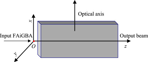
Figure 1. Schematic setup of the FAiGBA transmission performance in the uniaxial crystal.
In the above Eq. 1, the parameters ne and no, respectively, indicate the extraordinary and ordinary refractive indices of the uniaxial crystal. Symbol f = ne/no (the extraordinary refractive index divided by the ordinary refractive index) is formulated to describe the anisotropy of a crystalline material. There exist extensively, in nature, three main types of uniaxial crystals: the negative (f < 1), the positive (f > 1), and the isotropic crystals (f = 1). Nevertheless, experiment results showed that the crystal state can be changeable in different environments. With respect to the electro-optic crystal, for instance, the relationships between ne and external electric field strength E for positive and negative crystals are, respectively [38],
where μ denotes the linear electro-optic coefficient.
It is quite easy to obtain the incident radial FAiGBA by evenly distributing multiple two-dimensional Airy beams on a circle in the x–y plane, and the coordinates of ith (i = 1, 2 … , n) Airy beam in the initial plane is formulated through the following matrix transformation in the Cartesian coordinate system:
where α = 2π(i−1)/n Eq. 4 denotes the rotation angle. Hence, the electric field distribution of the radial FAiGBA at the source point O reads [39]
with
where xi and yi in Eqs 5, 6 are the source plane coordinates of the ith Airy beam; ω1 = εω0 represents the transverse beam radius, with ω0 and ε being the Gaussian source size and control factor, respectively; and a0 is the decay parameter which guarantees the photo-source containing limited energy. The Airy function [notation Ai (●)] is integrated into
where u in Eq. 7 signifies the variable of integration. One can recognize readily from the above theory that the radial FAiGBA with four beamlets is expressed as Eq. 8
In this study, we select the radial FAiGBA composed of x-linear and y-linear polarization beams, of which the electric field distribution is
The generalized Huygens–Fresnel integrals can effectively provide a “bridge” between the electric field distributions of incident and emerging beams within the framework of paraxial transmission theory, which are independently described as [40]
where z expresses the beam transmission distance; k = 2π/λ is the wave vector, with λ characterizing the incident wavelength. Substituting Eq. 9 into Eqs 10, 11 and after a number of algebraic manipulations, the general forms of the received beam array field in the uniaxial crystal orthogonal to the axis are obtained as follows:
and
where
with
with
Finally, the emerging radial FAiGBA optical field intensity is established on a certain receiver plane by recalling the following expression:
where j = x or y. The constant factor n0/(2cμ0) in the above equation is of no consequence because the intensity normalized processing is typically needed. Eqs 12–23 are the main results of this paper, which provide a simple but efficient method to study the radial FAiGBA evolution properties in several types of anisotropic media, especially the uniaxial electro-optic crystal.
3 Discussion and analyses
3.1 FAiGBA paraxial transmission properties in uniaxial crystals
In this subsection, we intend to probe into the FAiGBA evolution properties in three types of uniaxial crystals orthogonal to the optical axis. The chosen parameters are λ = 1.55 μm, a0 = 0.1, ε = 0.05, ω0 = 1 mm, and the Rayleigh length ZR = πω12/λ = 0.02 m in the following numerical simulation. Figure 2 illustrates the side transmission view and intensity contour graph of FAiGBA during its evolution in an isotropic crystal (no = ne = 1.5; f = 1). For comparison purposes, Figure 3 also depicts the intensity distribution of a single Airy beam. From these figures, it is evident that both the Airy beam and FAiGBA follow a ballistic trajectory along the y = x (or y = −x) direction under the condition f = 1; in other words, each type of Airy-derived wave accelerates along 4/π (or −4/π) on a random x–y cross-section within the isotropic space. In addition to having stronger optical power, the radial FAiGBA exhibits better symmetry than the Airy beam. Due to the meticulous design of multiple cubic diaphragms that can be loaded in the liquid crystal spatial light modulator, each beam self-bends independently to the mid-perpendicular position at the beginning of propagation, as shown in Figures 2A, B. Instead, the array of beams self-focuses on a central point termed as the auto-focus plane, as described in Figure 2C. As the transmission distance continuously increases, the FAiGBA once again breaks up into four petals (Figure 2D), eventually forming a square beam array losing its non-diffracting feature in the far field.
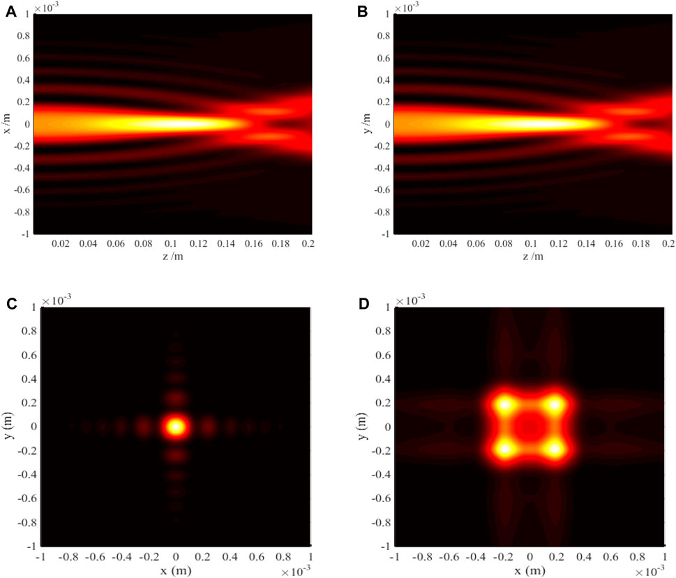
Figure 2. Radial FAiGBA intensity evolution in the isotropic crystal (no = ne = 1.5; f = 1). (A) Side view, (z, x) plane. (B) Side view, (z, y) plane. (C) Transversal contour graph, z = 5ZR. (D) Transversal contour graph, z = 10ZR.
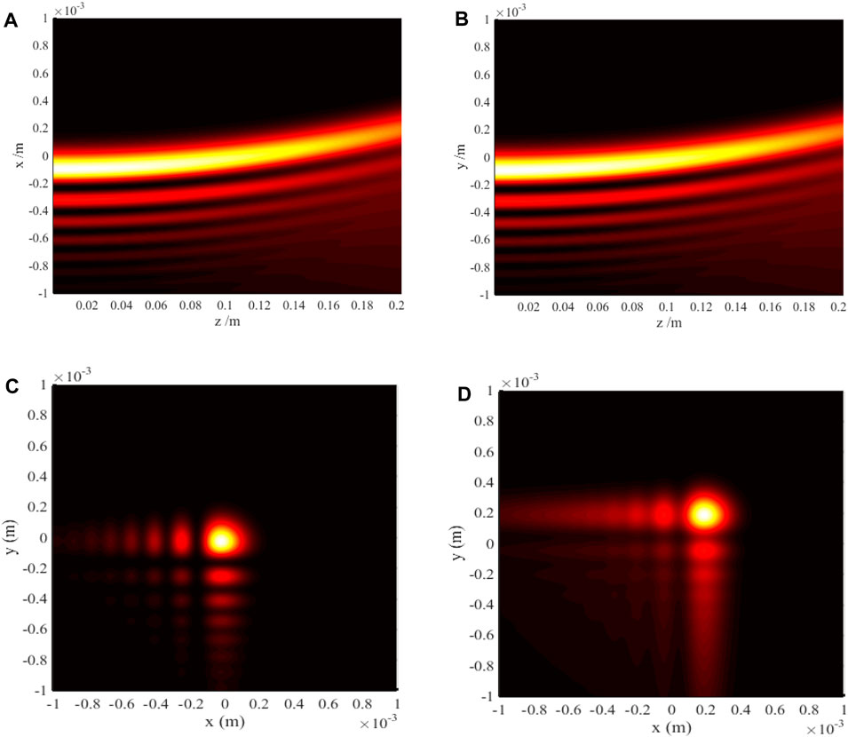
Figure 3. Single Airy beam intensity distribution in the isotropic crystal (no = ne = 1.5; f = 1). (A) Side view, (z, x) plane. (B) Side view, (z, y) plane. (C) Transversal contour graph, z = 5ZR. (D) Transversal contour graph, z = 10ZR.
We now focus on investigating the anisotropic effect on the evolvement process of the FAiGBA intensity in positive (f > 1) and negative uniaxial crystals (f < 1). By comparing Figures 4C, D with Figures 5C, D, it is evident that the four main lobes of the beam array convert into an ellipse on the auto-focus plane and a rounded rectangle in the far field owing to anisotropic characteristics of the crystal, of which the reason is listed as follows: while FAiGBA traverses the positive crystal (no = 1.5; ne = 2.0; f = 1.33), the self-bending of each beam in the x orientation quickens up, as demonstrated in Figure 4A. In striking contrast, the acceleration in the y direction gradually slows down (even slower than that in the isotropic medium), as shown in Figure 4B. Conversely, under identical conditions but with z being a negative crystal (no = 1.5; ne = 1.0; f = 0.67), the parabolic deviation value of FAiGBA is much larger in the y direction than that in the x direction, as can be seen in Figures 5A, B, resulting in a slender rectangular main spot size with its long axis along the y direction, as illustrated in Figure 5D. Furthermore, we emphasize from these figures that both the self-focus point and diffraction-free distance are influenced by the f-value ratio, which can be seen clearly from Figure 4C; Figure 5C.
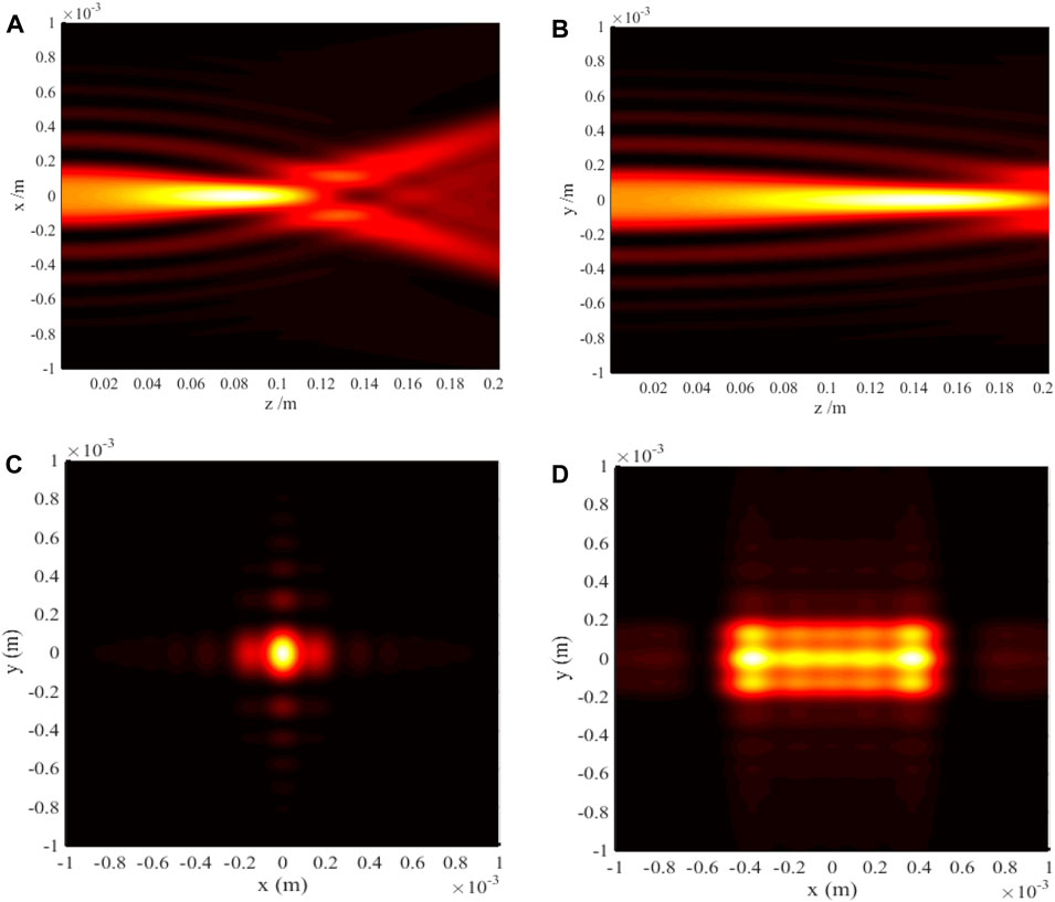
Figure 4. FAiGBA intensity evolvement rules in the positive crystal (no = 1.5; ne = 2.0; f = 1.33). (A) Side view, (z, x) plane. (B) Side view, (z, y) plane. (C) Transversal contour graph, z = 5ZR. (D) Transversal contour graph, z = 10ZR.
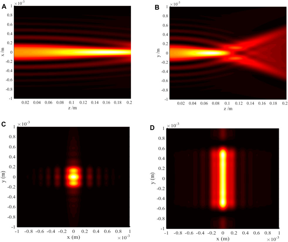
Figure 5. FAiGBA intensity evolvement rules in the negative crystal (no = 1.5; ne = 1.0; f = 0.67). (A) Side view, (z, x) plane. (B) Side view, (z, y) plane. (C) Transversal contour graph, z = 5ZR. (D) Transversal contour graph, z = 10ZR.
Next, we investigate linear polarization along the y axis of FAiGBA intensity distribution within uniaxial crystals. Extensive simulations demonstrate little influence of the f ratio on outline characteristics of this polarized beam array. We also illustrate the effect of different refractive indices n on the FAiGBA intensity silhouette and have noted that the wave profile remains isotropic. The variation rules of this polarized beam array versus the n of the anisotropic medium have been discovered, and the results are shown in Figures 6B–E. These figures suggest that the smaller the n is, the larger the displacement of the FAiGBA acceleration is on the same receiver plane; hence, the square silhouette of FAiGBA in Figure 6D2 is much bigger than that in Figures 6A2, B2. Additionally, it should be noted that FAiGBA’s self-focus plane becomes shorter with the decreasing value of n. The conclusion obtained above also applies to x-linear polarization of FAiGBA propagation when no = ne (f = 1) is fulfilled.
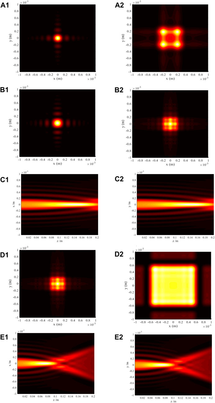
Figure 6. FAiGBA intensity distributions in the uniaxial crystal, y-linear polarization. (A) Transversal contour graph, n = 1.5; (A1) z = 5ZR; (A2) z = 10ZR. (B) Transversal contour graph, n = 2.0; (B1) z = 5ZR; (B2) z = 10ZR. (C) Side view, n = 2.0; (C1) (z, x) plane; (C2) (z, y) plane. (D) Transversal contour graph, n = 1.0; (D1) z = 5ZR; (D2) z = 10ZR. (E) Side view, n = 1.0; (E1) (z, x) plane; (E2) (z, y) plane.
In order to testify the validity of the paraxial mechanism of FAiGBA propagating in uniaxial crystals, the non-paraxial longitudinal component (z component) of this beam array is examined in the subsequent section. Figures 7A–C illustrate the relative intensity distribution at various cross-sections in comparison to an isotropic medium (top row), a positive uniaxial crystal (middle row), and a negative uniaxial crystal (bottom row), where the normalized intensity is chosen as the x component of the maximum intensity at the corresponding position. It is worth noting that the evolution characteristics of the FAiGBA in non-paraxial scenarios closely resemble those observed in the two paraxial directions, particularly over short distances, as evidenced by the comparison between Figure 2C; Figure 7A1. Nonetheless, the intensity of the longitudinal component is significantly weaker than that of the other two paraxial components, as indicated by the color bar inset in Figure 7. Consequently, the paraxial approximation proves effective in our model, as the longitudinal component can be considered negligible in magnitude.
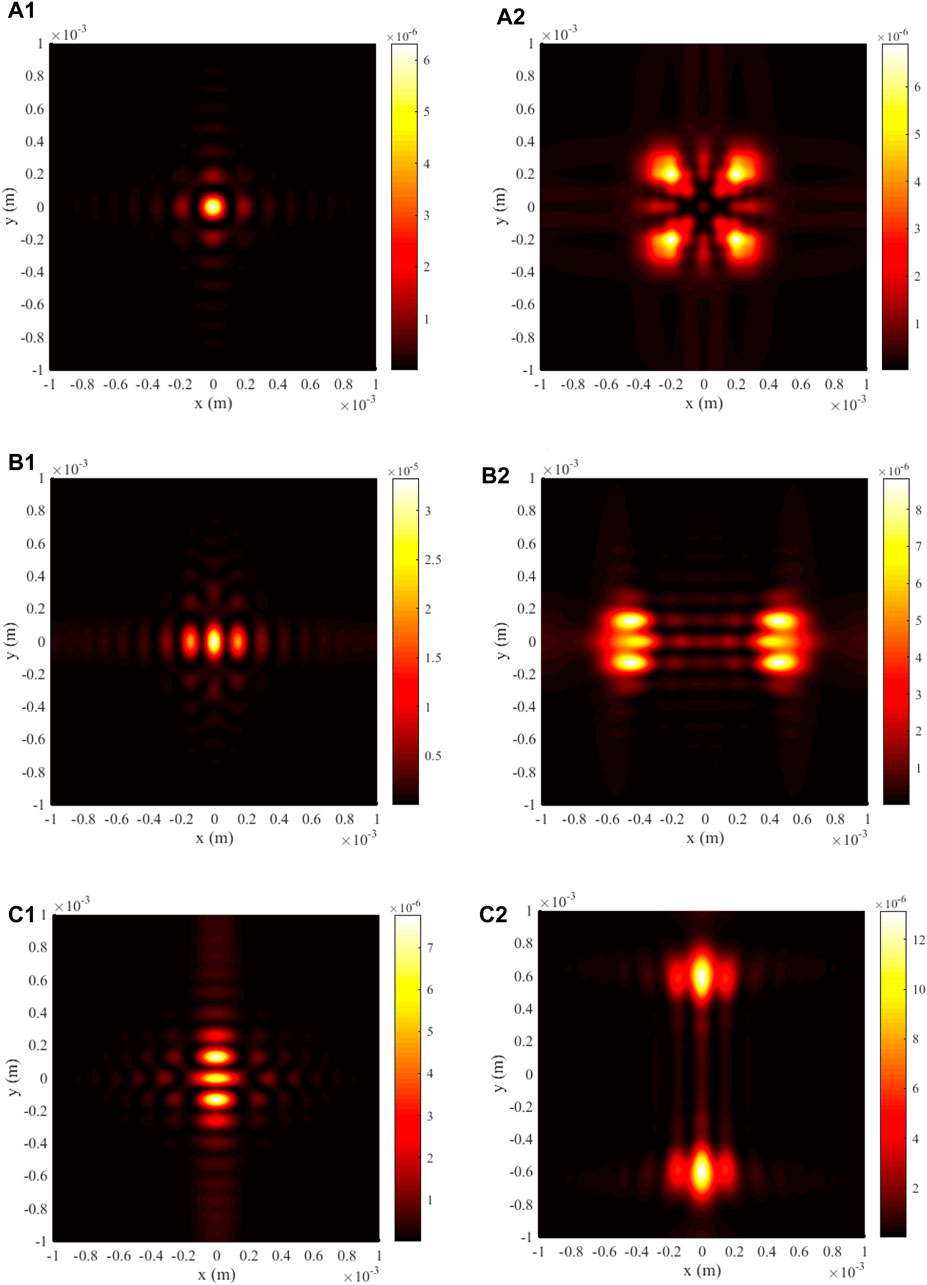
Figure 7. Transversal contour graph of the longitudinal component of FAiGBA at several observation planes in three types of uniaxial crystals. (A1–C1) z = 5ZR; (A2–C2) z = 10ZR. (A) no = ne = 1.5; f = 1. (B) no = 1.5; ne = 2.0; f = 1.33. (C) no = 1.5; ne = 1.0; f = 0.67.
3.2 Linear effect and linear electro-optic effect
Through the analysis of previous sections, it is easy to find that the anisotropic effect only occurs in x-linear polarization of paraxial FAiGBA. Therefore, we further explore the influence of changing ne on beam array evolution in this polarization. Here, calculation parameters no = 1.5 and z = 10ZR remain unchanged, and a linear function is fabricated to describe the relationship between ne and no as follows:
where U denotes the magnitude of a certain control strategy, by means of which the beam array intensity distribution on emerging cross-section is illustrated in Figure 8. It is readily obtained from these figures that the ratio of the FAiGBA acceleration varies according to the value of U. When U < 0, as shown in Figures 8A, B, the self-bending of the beam array in the y direction is much faster than that in the x direction. However, the self-bending degree of the beam array gradually turns around with increasing the U value. When U > 0, as shown in Figures 8D, E, the four main lobes of the FAiGBA constitute a rounded rectangle with its long axis along the x direction. Due to the interference and diffraction phenomenon caused by the four-beam array and the main and side petals of each beam, it is not possible to obtain a function describing the relationship between the relative maximum intensity of FAiGBA and U, as shown in Figure 8F.
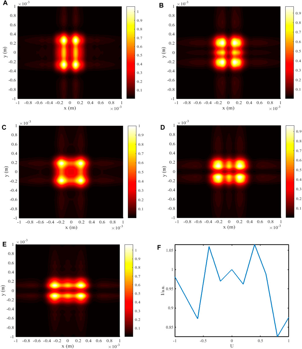
Figure 8. FAiGBA intensity evolvement rules in the uniaxial crystal versus the changing U. (A) U = −0.4. (B) U = −0.2. (C) U = 0. (D) U = 0.2. (E) U = 0.4. (F) Influence of U on FAiGBA’s maximum intensity value, where the brightest output intensity with U = 0 is regarded as the normalized parameter.
Figure 9 exhibits some fascinating discoveries regarding the position of the brightest spot in the beam array when further researching its change with U. Since our model has rotational symmetry, we will focus on the first quadrant, where the maximum intensity location of the beam is always greater than zero in both x and y directions. When U = −1, leading to a negative uniaxial crystal with its f = 0.67, the center location of the brightest spot is (x = 0.03264 mm; y = 0.51680 mm) at z = 10ZR on an intersecting surface. With the smoothly increasing U value, there are opposite trends observed in x and y axis coordinates, as shown in Figures 9A, B. This modulation has crucial signification in the field of micro/nano-optoelectronics. It is the transformation in both x and y orientations that enable us to regain a linearly polarized FAiGBA in the whole medium under the condition U = 0. There exists, of course, this kind of deviation (augment in the x axis and diminution in the y axis) even though U > 0, as illustrated in Figures 9C, D. Consequently, Figure 4D displays a bright thin line composed of four main petals near the x axis due to severe loss of acceleration along the y direction. As we understand, FAiBs function akin to a “snow blower,” gathering target particles and redirecting them elsewhere. With this in mind, the linear electro-optic modulation allows us to create two distinct sets of FAiGBA optical manipulations: the extraordinary (x component) and the ordinary (y component) versions. Furthermore, the ability to adjust the focus point of FAiGBA using different U values holds promise for applications in optical trapping.
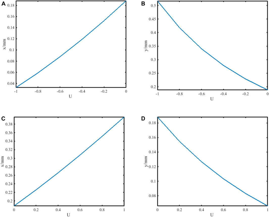
Figure 9. Position of FAiGBA’s brightest spot changed with factor U in the first quadrant. (A) −1 ≤ U ≤ 0, x direction. (B) −1 ≤U ≤ 0, y direction. (C) 0 ≤ U ≤ 1, x direction. (D) 0 ≤ U ≤ 1, y direction.
Although the relative maximum intensity appears chaotic and nonsensical, there is an approximately linear correlation between its coordinate position and U, especially close to U = 0. By recalling Eqs 2, 3, we confirm that a uniaxial electro-optic crystal with 1.4 ≤ ne ≤ 1.6 can be modulated by providing an external voltage of −2 kV ≤ U ≤ 2 kV if the rest parameters of the micron photonic crystal are set at no = 1.5 and μ = 29.62 × 10⁻¹² m/V. Figure 10 provides a closer examination of the influence of external voltage U on this modulation process. An electro-optic effect model is established by synthesizing data from FAiGBA’s maximum intensity location in both x and y directions along with external voltage U using the statistical matching method and linear inversion techniques, which are represented by the following Eqs 25, 26:

Figure 10. Influence of external voltage U on FAiGBA’s maximum intensity coordinates in the first quadrant. (A) x direction. (B) y direction.
The adjusted R2 parameters in the above two expressions reach 0.9997 and 0.9972, respectively, indicating that the electro-optic control exhibits an exceptional linear feature in FAiGBA route planning for anisotropic crystals, such as photonic crystal and carbon nanotube cable, especially in the areas of optical communication, optical manipulation, and trapping.
Due to natural birefringence, the working point of the uniaxial electro-optic crystal tends to shift with temperature fluctuations, resulting in a slight alteration in the trajectory of the FAiGBA. In our model, both the ordinary (no) and extraordinary (ne) refractive indices increase with increasing temperatures [41], as illustrated in Figure 11. Utilizing these numerical values, the FAiGBA intensity distribution of the x component at the cross-section z = 10ZR of the uniaxial electro-optic crystal under temperatures T = 293 K and 323 K is depicted in Figure 12. The profiles of Figures 12A, B show minimal divergence. The central position of the brightest spot [(x = 0.1680 mm; y = 0.1880 mm) at T = 293 K and (x = 0.1740 mm; y = 0.1860 mm) at T = 323 K] further indicates that the temperature exerts a negligible influence on the evolution characteristics of the FAiGBA. Furthermore, implementation of temperature compensation and differential structure can better enhance the stability of uniaxial electro-optic crystals.
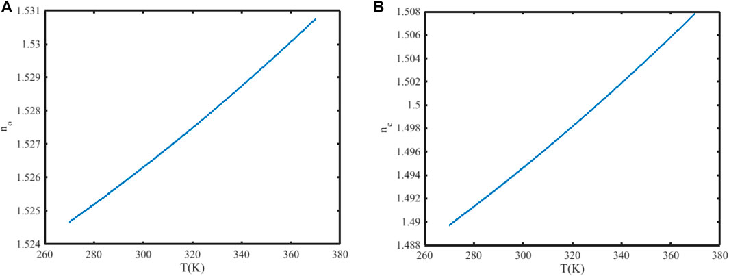
Figure 11. Relation schemas between the refractive index of uniaxial crystal and temperature. (A) Parameter no. (B) Parameter ne.
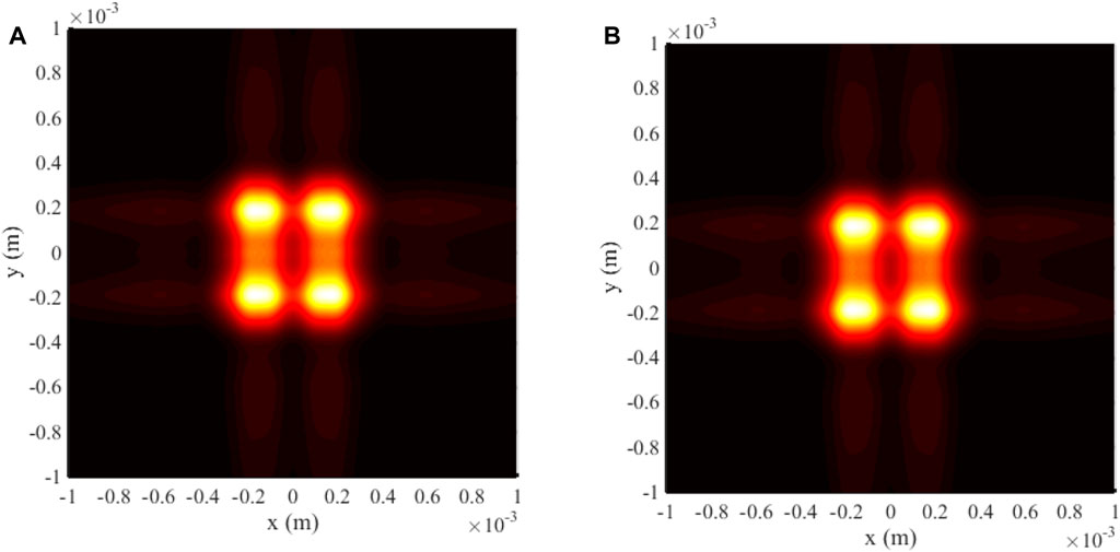
Figure 12. FAiGBA intensity profile at two different temperatures. (A) T = 293 K. (B) T = 323 K.
4 Conclusion
In summary, we have derived the analytical evolution expression for the radial FAiGBA in uniaxial crystals orthogonal to the optical axis under the paraxial approximation. Detailed analysis reveals the distinct behaviors of the intensity distribution in the x and y components. As examples, the intensity distribution and side view of the FAiGBA propagating in three types of uniaxial crystals are explored. It concludes that the ratio of the extraordinary refractive index to the ordinary index plays a vital role in the x-linear polarization of the FAiGBA evolution rules, whereas there is little influence of the f ratio on the outline characteristics of the y linearly polarized beam array; that is, synthetic radial FAiGBAs can maintain their linear properties only within isotropic media as a whole. In addition, we systematically discuss the linear electro-optic effect when this beam array transmits in the electro-optic crystal. It is clear that the x-coordinate of the brightest spot on the first quadrant increases with the smoothly increasing U values from −1 to 1, whereas the y-coordinate exhibits the opposite trend. In addition, there is an approximately linear correlation between its coordinate position and external voltage U, especially close to U = 0, which is verified by the statistical matching method and its adjusted R2 parameters. The influence of the non-paraxial longitudinal component and temperature on FAiGBA evolution characteristics is also examined to confirm the validity of the paraxial mechanism of this beam array propagating in uniaxial crystals. It can be realistically expected that these comprehensive analytical expressions and conclusions regarding the paraxial propagation of FAiGBA in uniaxial electro-optic crystals will offer valuable insights for designing pathways for various applications in micro- and nano-control, optical fiber communication, optical trapping, and manipulation fields.
Data availability statement
The datasets presented in this study can be found in online repositories. The names of the repository/repositories and accession number(s) can be found in the article/Supplementary Material.
Author contributions
LJ: writing–original draft and writing–review and editing. YX: writing–review and editing.
Funding
The author(s) declare that financial support was received for the research, authorship, and/or publication of this article. This work was supported by the Natural Science Foundation of Hubei Province (No. 2024AFD109).
Conflict of interest
The authors declare that the research was conducted in the absence of any commercial or financial relationships that could be construed as a potential conflict of interest.
Publisher’s note
All claims expressed in this article are solely those of the authors and do not necessarily represent those of their affiliated organizations, or those of the publisher, the editors, and the reviewers. Any product that may be evaluated in this article, or claim that may be made by its manufacturer, is not guaranteed or endorsed by the publisher.
References
1. Ruiz-Jiménez C, Nóbrega KZ, Porras MA On the dynamics of Airy beams in nonlinear media with nonlinear losses. Opt Express (2015) 23(7):8918–28. doi:10.1364/oe.23.008918
2. Siviloglou G, Christodoulides D. Accelerating finite energy Airy beams. Opt Lett (2007) 32:979–81. doi:10.1364/ol.32.000979
3. Anaya-Contreras JA, Zúñiga-Segundo A, Moya-Cessa HM. Airy beam propagation: autofocusing, quasi-adiffractional propagation and self-healing. J Opt Soc America A (2021) 38(5):711–8. doi:10.1364/josaa.418533
4. Efremidis NK, Chen Z, Segev M, Christodoulides DN Airy beams and accelerating waves: an overview of recent advances. Optica (2019) 6(5):686–701. doi:10.1364/optica.6.000686
5. Suarez RAB, Neves AAR, Gesualdi Marcos RR Optical trapping with non-diffracting Airy beams array using a holographic optical tweezers. Opt Laser Technol (2021) 135(1):106678. doi:10.1016/j.optlastec.2020.106678
6. Polynkin P, Kolesik M, Moloney JV, Siviloglou GA, Christodoulides DN Curved plasma channel generation using ultraintense Airy beams. Science (2009) 324(5924):229–32. doi:10.1126/science.1169544
7. Abdollahpour D, Suntsov S, Papazoglou DG, Tzortzakis S. Spatiotemporal Airy light bullets in the linear and nonlinear regimes. Phys Rev Lett (2010) 105(25):253901. doi:10.1103/physrevlett.105.253901
8. Podanchuk DV, Goloborodko AA, Kotov MM, Kovalenko AV, Kurashov VN, Dan’ko VP, et al. Airy–Talbot plasmon: an accelerating self-imaging surface wave. Opt Lett (2022) 47(7):1887–90. doi:10.1364/ol.452543
9. Jia S, Vaughan JC, Zhuang X. Isotropic 3D super-resolution imaging with a self-bending point spread function. Nat Photon (2014) 8(4):302–6. doi:10.1038/nphoton.2014.13
10. Peng Y, Hu J, Xiang Y, Xu D, Liu Y. Effect of Airy Gaussian vortex beam array on reducing intermode crosstalk induced by atmospheric turbulence. Opt Express (2019) 27(26):37986–98. doi:10.1364/oe.27.037986
11. Zhang Z, Jing-Jiao L, Peng Z, Pei-Gen N, Prakash J, Yang H, et al. Generation of autofocusing beams with multi-Airy beams. Acta Physica Sinica (2013) 62(3):034209. doi:10.7498/aps.62.034209
12. Trinkler L, Pankratov V, Trukhin A, Berzina B, Chou MMC, Chang L Anisotropic photoluminescence of β-LiGaO2 crystal. Opt Mater (2022) 132:112856. doi:10.1016/j.optmat.2022.112856
13. Bryantsev BS, Kalinovich AA, Zakharova IG Optical vortices in quadratic nonlinear media with nonlinear absorption. Bull Russ Acad Sci Phys (2021) 85(1):20–4. doi:10.3103/s1062873821010081
14. Danlina X, Wu Y, Lin Z, Jiang J, Zhenwua M, Huang Z, et al. Propagation of the odd-Pearcey Gauss beam in the uniaxial crystals with the Pockels effect. Opt Laser Technol (2022) 151:108067. doi:10.1016/j.optlastec.2022.108067
15. Ciattoni A, Cincotti G, Palma C. Circularly polarized beams and vortex generation in uniaxial media. J Opt Soc America A (2003) 20(1):163–71. doi:10.1364/josaa.20.000163
16. Guokai H, Xu M, Sun X, Liu B, Zhang L, Ren H, et al. Rapid growth of the gradient deuterium deuterated potassium dihydrogen phosphate crystal. Cryst Growth Des (2024) 24(1):567–72. doi:10.1021/acs.cgd.3c01278
17. Shang J, Yang J, Hao H, Li Q, Zhang L, Sun J Study on light leakage phenomenon of Lithium Niobate electro-optic Q-switching crystals. J Synth Crystals (2020) 49(6):1035–9. doi:10.16553/j.cnki.issn1000-985x.20200509.001
18. Jiang F, Wang Y, Qi Y, Zhang X. Design of reflective structure electro-optic modulated on-reciprocal phase modulator. Opt Tech (2021) 47(2):155–8. doi:10.13741/j.cnki.11-1879/o4.2021.02.005
19. Zhong Y, Cheng T. Experimental study of LD side-pumped Tm:YAG electro-optically Q-switched laser. Chin J Quan Electron (2022) 39(5):736–40. doi:10.3969/j.issn.1007-5461.2022.05.006
20. Zhong D, Ji Y. Electro-optical composite logic gates based on periodically poled lithium niobate crystal. Acta Photonica Sinica (2015) 44(5):523004. doi:10.3788/gzxb20154405.0523004
21. Yang G, Li Z, Wu K. Periodically poled monolayer lithium niobate for photonic chips of quantum devices. ACS Appl Opt Mater (2023) 1(1):115–22. doi:10.1021/acsaom.2c00015
22. Zhou G, Chen R, Chu X. Propagation of Airy beams in uniaxial crystals orthogonal to the optical axis. Opt Express (2012) 20(3):2196–205. doi:10.1364/oe.20.002196
23. Mei-Ling Z, Chi-Dao C, Chen B, Peng X, Yu-Lian P, Dong-Mei D. Propagation of an Airy-Gaussian beam in uniaxial crystals. Chin Phys B (2015) 24(12):124102. doi:10.1088/1674-1056/24/12/124102
24. Fu D, Dongmei D. Nonparaxial propagation of an Airy-Gaussian beam in uniaxial crystal orthogonal to the optical axis. Opt Commun (2016) 280:280–6. doi:10.1016/j.optcom.2016.06.018
25. Yu W, Zhao R, Deng F, Huang J, Chen C, Yang X, et al. Propagation of Airy Gaussian vortex beams in uniaxial crystals. Chin Phys B (2016) 25(4):044201. doi:10.1088/1674-1056/25/4/044201
26. Li D, Peng X, Peng Y, Zhang L, Deng D. Nonparaxial evolution of the Airy–Gaussian vortex beam in uniaxial crystal. J Opt Soc America B (2017) 34(4):891–8. doi:10.1364/josab.34.000891
27. Zhang J, Zhou K, Liang J, Lai Z, Yang X, Deng D. Nonparaxial propagation of the Chirped Airy vortex beams in uniaxial crystal orthogonasl to the optical axis. Opt Express (2018) 26(2):1290–304. doi:10.1364/oe.26.001290
28. Jian Y, Xiao S, Yao L, Liu S, Jin L. Propagation of the finite energy Airy-Hermite-Gaussian beams in uniaxial crystals orthogonal to the optical axis. J Mod Opt (2017) 64(4-6):616–23. doi:10.1080/09500340.2016.1254829
29. Zhou G, Chen R, Chu X. Propagation of cosh-Airy beams in uniaxial crystals orthogonal to the optical axis. Opt Laser Technol (2019) 116:72–82. doi:10.1016/j.optlastec.2019.03.016
30. Wu X, Xie J, Deng D. Paraxial propagation of radially polarized first-order chirped Airy Guassian beams in uniaxial crystals orthogonal to the optical axis. Appl Phys B (2019) 125(6):87. doi:10.1007/s00340-019-7204-1
31. Liu H, Yuan L. Separating radial and azimuthal polarizations of circular Airy vortex beam via uniaxial crystal. Opt Express (2023) 31(14):22507–18. doi:10.1364/oe.491309
32. Liu H, Zhang J, Huilin P, Jiankang X, Ronghui X, Yuan L. Controlling the abrupt autofocusing of circular Airy vortex beam via uniaxial crystal. Photonics (2022) 9(12):943. doi:10.3390/photonics9120943
33. Jin L, Xiang Y. Non-paraxial transformation of finite Airy Gaussian beam array in isotropic space. Results Phys (2022) 39:105791. doi:10.1016/j.rinp.2022.105791
34. Jin L, Zhang Z, Wang N, Liu Z, Deng Y, Fu Y. Intensity distribution of partially coherent array finite Airy beams propagating in atmospheric turbulence. Int J Opt (2021) 2021:1–11. doi:10.1155/2021/6649144
35. Baumgartl J, Mazilu M, Dholakia K. Optically mediated particle clearing using Airy wave packets. Nat Photon (2008) 2(11):675–8. doi:10.1038/nphoton.2008.201
36. Tan L, Liu N, Lu F, Liu D, Yu B, Li Y, et al. Quantitative characterization of autofocusing and trapping of multi-Airy vortex beams. Phys Rev A (2023) 107(4):043501. doi:10.1103/physreva.107.043501
37. Ciattoni A, Crosignani B, Di Porto P Vectorial theory of propagation in uniaxially anisotropic media. J Opt Soc America A (2001) 18(7):1656–61. doi:10.1364/josaa.18.001656
38. Fan X, Chen W, Zhang Q, Zhao J, Pei Z. Analytical calculation of beam phase-shift in cuboid isotropic electro-optic crystal with polarization effect. Proc CSEE (2022) 42(24):9126–36. doi:10.13334/j.0258-8013.pcsee.212073
39. Jin L, Xiang Y. Folded resonator for glucose solution density detection based on Airy beam arrays. Front Phys (2022) 10:909206. doi:10.3389/fphy.2022.909206
40. Ciattoni A, Palma C. Optical propagation in uniaxial crystals orthogonal to the optical axis: paraxial theory and beyond. J Opt Soc America A (2023) 20(11):2163–71. doi:10.1364/josaa.20.002163
Keywords: laser optics, finite Airy–Gaussian beam array, uniaxial crystals, electro-optic crystal, extraordinary and ordinary refractive, indices
Citation: Jin L and Xiang Y (2024) Transformation regulation of the paraxial finite Airy–Gaussian beam array propagating through uniaxial electro-optic crystals. Front. Phys. 12:1426495. doi: 10.3389/fphy.2024.1426495
Received: 04 May 2024; Accepted: 14 June 2024;
Published: 12 July 2024.
Edited by:
Xiaoming Duan, Harbin Institute of Technology, ChinaReviewed by:
Preeti Gupta, Leibniz Institute for Solid State and Materials Research Dresden (IFW Dresden), GermanyGiuseppe Brunetti, Politecnico di Bari, Italy
Copyright © 2024 Jin and Xiang. This is an open-access article distributed under the terms of the Creative Commons Attribution License (CC BY). The use, distribution or reproduction in other forums is permitted, provided the original author(s) and the copyright owner(s) are credited and that the original publication in this journal is cited, in accordance with accepted academic practice. No use, distribution or reproduction is permitted which does not comply with these terms.
*Correspondence: Long Jin, MjAxNDAwMDdAaHVhdC5lZHUuY24=