 Alberto Carrasco-Casado
 Koichi Shiratama1
 Dimitar Kolev
 Morio Toyoshima
- 1Space Communication Systems Laboratory, National Institute of Information and Communications Technology (NICT), Tokyo, Japan
- 2Wireless Networks Research Center, National Institute of Information and Communications Technology (NICT), Tokyo, Japan
The Japanese National Institute of Information and Communications Technology (NICT) plans to launch a 6U CubeSat into Low Earth Orbit (LEO) during the Japanese fiscal year 2025. The primary payload for this mission is CubeSOTA (CubeSat’s Small Optical TrAnsponder), a miniaturized free-space optical communication terminal currently under development. A key component of this terminal is the optical amplifier, which must provide high transmission gain to overcome the significant free-space losses caused by the long distances involved in space communications. Additionally, to enable seamless integration into communication networks, the optical amplifier must support bidirectional communications. To achieve this, the amplifier incorporates a 2-in-1 design, integrating a high-power amplifier (HPA) for the transmission path and a low-noise amplifier (LNA) for the reception path. This paper presents the key features of this recently developed optical amplifier and its space qualification process, which is essential before its integration into the CubeSOTA terminal for launch. The developed amplifier features a 9 × 9.5 cm footprint for compatibility with the CubeSat standard, a reduced height of 3.6 cm and mass of 0.56 kg, while the HPA can deliver an output exceeding 2 W and the LNA is optimized for Doppler compensation and low noise with a noise figure below 4.5 dB. The environmental testing focuses on the amplifier’s most critical features, namely, its performance across varying temperature conditions in a vacuum and its power consumption under different operation modes.
1 Introduction
The NICT Space Communication Systems Laboratory has been actively engaged in space-based optical communications, conducting pioneering in-orbit demonstrations for nearly 30 years [1]. Building on this foundation, NICT plans to launch a 6U CubeSat into Low Earth Orbit (LEO) during the Japanese fiscal year 2025 with the goal of carrying out laser communications experiments with both ground stations and with HAPS (High-Altitude Platform Station) [2]. The primary payload for this mission is CubeSOTA, named after the successful SOTA (Small Optical TrAnsponder) mission [3], a miniaturized optical communication terminal based on the design of the highly versatile FX (Full Transceiver) terminal, recently prototyped and validated by NICT [4]. The key difference between CubeSOTA and FX is that CubeSOTA relies on the satellite’s attitude control system for coarse pointing, whereas FX employs a gimbal. CubeSOTA is designed to support bidirectional communications, for which the erbium-doped fiber amplifier (EDFA) is a critical component for delivering enough transmitting and receiving gain [5, 6]. Consequently, the EDFA presented in this paper features both a high-power amplifier (HPA) for the transmission path and a low-noise amplifier (LNA) for the reception path, capable of operating independently while being integrated within the same 2-in-1 miniaturized device.
The development of compact and high-performance optical amplifiers that meet the stringent size, weight, and power (SWaP) constraints of CubeSats is a complex challenge. As a reference to the state of the art, references [7, 8] present a device most similar to that described in our work. This system comprises two separate modules: an HPA (0.65 kg, 3 W output, 10 × 10 × 4.2 cm) and an LNA (0.1 kg, 9 × 5.4 × 1.55 cm). In contrast, our device integrates both functionalities into a single compact unit (9 × 9.5 × 3.6 cm, 0.56 kg), which not only reduces size and weight compared to the HPA module alone but also achieves a 20% higher mass density (1.82 g/cm3 vs. 1.515 g/cm3), a critical factor for miniaturization. With a power output of 2 W (albeit lower than 3 W) and an LNA noise figure of 4.2 dB (maximum theoretical 4.5 dB) versus a nominal 5 dB, our design demonstrates superior integration of functionality in a smaller footprint. In addition to the module design and development, its space qualification and performance validation under varying environmental conditions are essential steps before its integration into the satellite’s payload [9,10] to ensure the device not only survives but also performs as expected throughout the mission.
Motivated by all the demanding requirements described above, this paper presents a detailed discussion of all the design choices made to manufacture the flight version of the optical amplifier unit conceived for NICT’s CubeSOTA mission, its main characteristics, and the complete space qualification carried out prior to its integration within the mission payload. To the best of the authors’ knowledge, it is the world’s smallest EDFA to integrate both an HPA and an LNA for space operation. The manuscript first provides an overview of the final flight unit, detailing key design choices and the results of the full space qualification. It then focuses on the most critical aspects of in-orbit operation, including performance in vacuum conditions, thermal behavior under varying temperatures, and power consumption across different operational modes. These validations are essential to ensuring the amplifier’s reliability when integrated into the terminal and the satellite bus.
2 EDFA design considerations
This EDFA was designed to meet the CubeSat standard, featuring a compact form factor of 9 × 9.5 cm with a height of 3.6 cm and a weight of 0.56 kg. It operates on a +12 V ± 0.25 V power supply, ensuring compatibility with the CubeSOTA mission’s satellite bus. The LNA and HPA modules are integrated into a single physical unit but can be operated independently. The HPA’s control mode is ACC (Automatic Current Control), and the LNA’s is APC (Automatic Power Control). The microcontrollers of the HPA and LNA are equipped with universal asynchronous receiver-transmitter (UART) ports to communicate by using TTL signals with the satellite’s onboard computer (OBC). In the case of the HPA, LOS (Loss Of Signal) protection with auto-recovery was implemented to ensure safe automatic operation. This function is necessary to disable the unit in the absence of an input signal, whether due to a malfunction of the modem or an error in the control software, in order to prevent potential permanent damage, and to automatically re-enable the amplifier once the signal is restored.
The electrical interface comprises a 12-pin connector with dual-pin configuration VDC, GND, and UART (Tx/Rx) signals for redundancy. The EDFA case interior was filled with epoxy to enhance thermal transfer, and silicone rings were used on optical components to protect them from shock and vibration. Optical fibers of 1-m length with miniaturized connectors (approximately 20 mm) were employed to reduce the device footprint. For the EDFA integration within the lasercom terminal’s limited space, the fiber bending radius must be also minimized. The LNA uses G.652.D fibers, permitting a 25 mm radius with a power loss under 0.03 dB at 1,550 nm, or 20 mm with 0.05 dB. The HPA uses G.657.A2, allowing a 15 mm radius with under 0.05 dB loss, or 10 mm with 0.1 dB.
To protect the unit from radiation, an aluminum case was used to shield the electronics and radiation-hardened fibers were used as they remain partially exposed outside the protective case. These fibers are specially manufactured using high-purity fused silica with low hydroxyl (OH) content and specialized dopants to withstand the high levels of ionizing radiation encountered in space, ensuring that their optical performance and structural integrity are maintained [11, 12]. No measures have been taken to counteract the spectral shift in gain, as this effect is considered negligible. Even in the worst-case scenario, a shift exceeding 0.1 nm is not anticipated, resulting in a minimal impact on gain [13, 14].
Both the HPA and LNA are designed as two-stage amplifiers to achieve the required high gain while maintaining low noise levels to maximize the signal-to-noise ratio (SNR). To fit the CubeSOTA mission, both EDFAs were optimized to provide maximum gain at their respective wavelengths (transmitting wavelength around 1,540 nm and receiving wavelength around 1,560 nm). In the HPA section, three isolators are used, one after the input and another after each stage, to achieve an input-output isolation exceeding 30 dB.
As for the LNA section, it is critical to remove the unwanted ASE (Amplified Spontaneous Emission) noise to maximize the SNR before reaching the modem’s receiver. For this reason, there is a filter after each stage with a ∼1,560 nm central wavelength. Both filters are hybrid, incorporating an isolator as well, with a 2-stage filter in the second stage to achieve an isolation exceeding 30 dB. To design the filter’s bandwidth, it is important to consider the Doppler shift caused by the satellite’s relative motion, which leads to variations in the received wavelength. Assuming a maximum speed of v = 7.7 km/s for LEO (at 400 km as the lowest typical LEO altitude, with slower speeds at higher altitudes), the Doppler shift can be calculated as Δλ = λ0 (v/c) = 1,560 nm (7.7 km/s/300,000 km/s) ≈ 0.04 nm. Since this Δλ can occur in both directions, the total filter bandwidth should be greater than 0.08 nm. To accommodate the entire possible Doppler shift with a margin of 5 times, a 0.4 nm @-0.5 dB bandwidth was chosen for both filters.
LC/PC connectors were selected for the HPA’s input and LNA’s output since they are directly interfaced with SFP + industrial-grade high-speed transceivers in the modem, while HPA’s output is connected to the transmitting optics, thus the connector type is FC/APC to minimize back reflections at high power towards the fiber’s core, and LNA’s input is FC/UPC because it is connected directly to the receiving optics. Regarding component placement, the HPA is positioned at the bottom and the LNA at the top, a configuration that optimizes heat management during satellite integration, as the HPA is expected to operate at higher temperatures.
Table 1 provides a consolidated qualitative and quantitative summary of the design considerations outlined in this section.
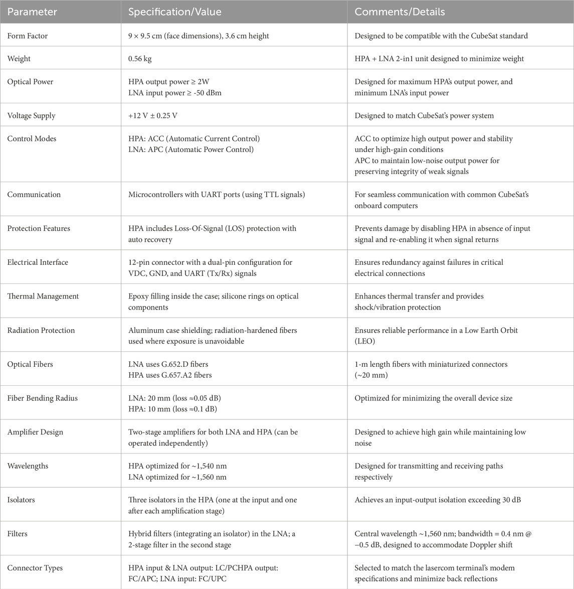
Table 1. Summary of CubeSOTA’s EDFA design considerations.
3 Environmental validation
The EDFA’s space qualification was conducted at the Center for Nanosatellite Testing (CeNT) of the Kyushu Institute of Technology (Japan), which is equipped with facilities specialized in space environmental testing for components as well as nanosatellites up to 50 cm and 50 kg. Figure 1 presents an image of the flight-model CubeSat’s EDFA alongside visuals from the environmental tests. The ISO 15864:2021 (Space systems—General test methods for space craft, subsystems and units) [15] and ISO 19683:2017 (Space systems—Design qualification and acceptance tests of small spacecraft and units [16] standards were followed to as a guide to prepare the module for the environmental tests. These documents provide a comprehensive framework outlining standardized procedures and acceptance criteria for evaluating the performance of spacecraft and their components under simulated space conditions, including thermal, vibration, and vacuum tests.
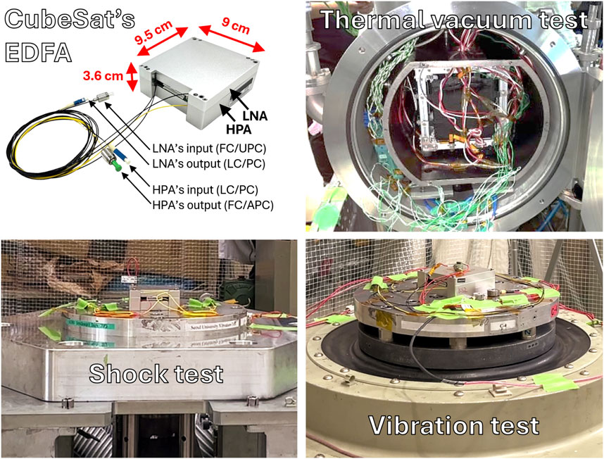
Figure 1. Flight-model CubeSat EDFA and images from the environmental tests.
Following the recommendations of the aforementioned ISO standards, three types of vibration tests were conducted: modal, sinusoidal and random. Modal vibration tests are used to ascertain the natural frequencies of the device under test and are performed at the beginning and end of the vibration tests to identify any changes in the natural frequencies. Sinusoidal vibration tests ranged from 5 to 100 Hz at 2.5 g and from 100 to 140 Hz at 1.25 g at a rate of 2 October/min for each orthogonal axis (1 g = 9.80665 m/s2). Random vibration tests ranged from 20 to 2,000 Hz and lasted 2 min per axis. The test sequence followed a four-step cycle: modal-sinusoidal-random-modal for each orthogonal axis. Additionally, shock tests were conducted up to 1,000 g from 100 to 5,000 Hz for each axis.
The HPA’s optical output power exhibited less than 0.15 dB of variation during these tests while operating at full gain (output power ≈33.2 dBm). No meaningful variation was measured in the LNA’s optical output power (output power = 3.5 dBm). All control and monitoring functions operated seamlessly throughout the tests, and all electrical connectors, both internal and external, remained in place.
The total ionization dose (TID) tests were conducted using Cobalt-60 as the radiation source to assess the effect of gamma radiation exposure. The EDFA was subjected to a total dose exceeding 20 krad at a rate of 5 rad/s over approximately 2 h, a typical exposure level for LEO missions lasting one to 3 years [17]. Testing was performed at both the component level and system level using dedicated test units. For the component-level test, the internal voltage and current were measured in two PCB samples to evaluate the buck-boost DC/DC converters and low-dropout regulators behavior before and after radiation exposure. Both parameters remained within nominal ranges, with voltage variations below 1% and current variations below 2%.
As for the system-level TID tests, a complete EDFA test unit was used to measure the output power of the LNA, and both stages of the HPA before and after exposure to radiation. The LNA’s input power was −20 dBm with a gain of 30 dB, resulting in an output power of 10.1 dB before the TID test and 9.27 dB afterward, corresponding to a 0.83 dB loss after 20 krad. The HPA’s first stage input power was 0 dBm and the output power varied from 17.8 dBm before the TID test to 17.1 dBm after TID test, representing an 0.7 dB loss. Similarly, the HPA’s second stage had an input power of 15.6 dBm, with output power dropping slightly from 33.2 dBm to 33.0 dBm, indicating a minimal 0.2 dB loss.
Thermal Vacuum (TVAC) tests are among the most critical because of the strong dependence of the EDFA behavior, in particular output optical power, with temperature. This is especially relevant when heat cannot be dissipated due to the lack of air in vacuum conditions and the absence of a cooling system, which would otherwise introduce significant constraints in terms of size and complexity. For TVAC testing, the unit was placed inside a 20 cm3 cage with heaters attached to each side. This cage was positioned in the first compartment of the vacuum chamber, while the electrical (12 cables, including power and control lines) and optical interfaces (four optical fibers) were routed through the second compartment, where the light sources and power meters were placed to be controlled from outside of the vacuum chamber, since the only interface was electrical from the second compartment to the control PC outside the chamber.
Eight thermocouples were attached to the test unit to monitor the case temperature, with one on each lateral side and two on both the top and the bottom. As expected, the bottom side, where the HPA is located, consistently reached temperatures 5 and 10° higher than the top side when the HPA was active. Therefore, the sensor in the hottest position was selected for the primary temperature measurements, which is typically a similar value to the internal onboard sensor (used for in-orbit telemetry), since it is located among the 2 EDFAs and close to the HPA as well. TVAC testing was conducted within a pressure range of 10−6 to 10−7 mbar and a temperature range from −23°C (initial temperature for cold cycles) and +55°C (initial temperature for hot cycles).
Prior to the extensive TVAC campaign, which spanned over 24 h continuously, a preliminary test was performed on the HPA at extreme temperatures of +60°C and −25°C and for enough time to verify the correct EDFA operation at extreme conditions and identify the power evolution up to a stationary state when operated at the maximum driving current (ACC mode). Typically, the output power can be maintained for a long time within a temperature range of approximately −20°C to 60°C. Below −20°C, the HPA takes a few minutes to naturally heat itself while increasing its output power and stabilizing above −10°C, eventually converging towards 0°C. Above 60°C, however, the amplifier experiences rapid self-heating, leading to an initial 10% drop in output power within the first 20 min. The power reduction then gradually stabilizes at approximately 15% as the temperature approaches 90°C, the maximum operational limit of the EDFA (see Figure 2).
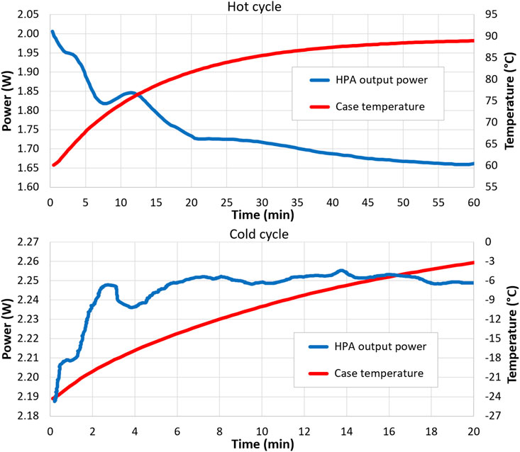
Figure 2. Long duration initial tests under extreme temperatures.
Figure 3 shows the extensive TVAC campaign, which included 8 functional tests (FT), one before the TVAC and 7 during the TVAC, with the first one performed at room temperature (FT0RT), and the other 6 divided into 3 full cycles starting with a hot cycle (FTXHC) with +55°C as initial temperature, followed by a cold cycle (FCXCC) with −23°C as initial temperature. Each of these 6 tests were conducted after the temperature had stabilized for approximately 1 h. To account for the time required for the vacuum chamber to reach each target temperature during all these cycles as well as the cycles themselves, the entire campaign lasted 28 consecutive hours. In each functional test, the LNA was activated for 5 min, followed by the HPA 1 min later, remaining on for 20 min. In both cases, both amplifiers operated at maximum gain throughout their respective test periods.
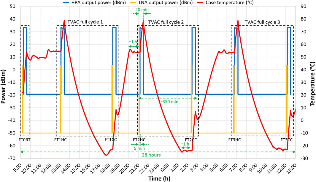
Figure 3. Extensive TVAC campaign showing cycles and functional tests (FT) sequence.
The LNA’s output power remains highly stable across all temperatures, with maximum variations of just 0.02 dB and temperature fluctuations within 0.2°C due to the low signal levels. In contrast, the HPA’s output power exhibits a strong dependence on the temperature. Figure 4 represents the HPA’s TVAC functional tests (FT) under vacuum conditions across 3 full cycles, including both hot cycles (HC) and cold cycles (CC). The repeatability between similar FTs is within 2% of the output power. However, significant variations are observed between HC and CC. On one hand, the HPA generates 200–300 mW higher power under CCs compared to HCs, as the temperature rises rapidly, and the module cannot dissipate excess heat in a vacuum environment. During CCs, the output power decreases by less than 5% from the initial maximum value, and by over 10% during HCs, being the initial output power already about 10% lower in HCs than in CCs.
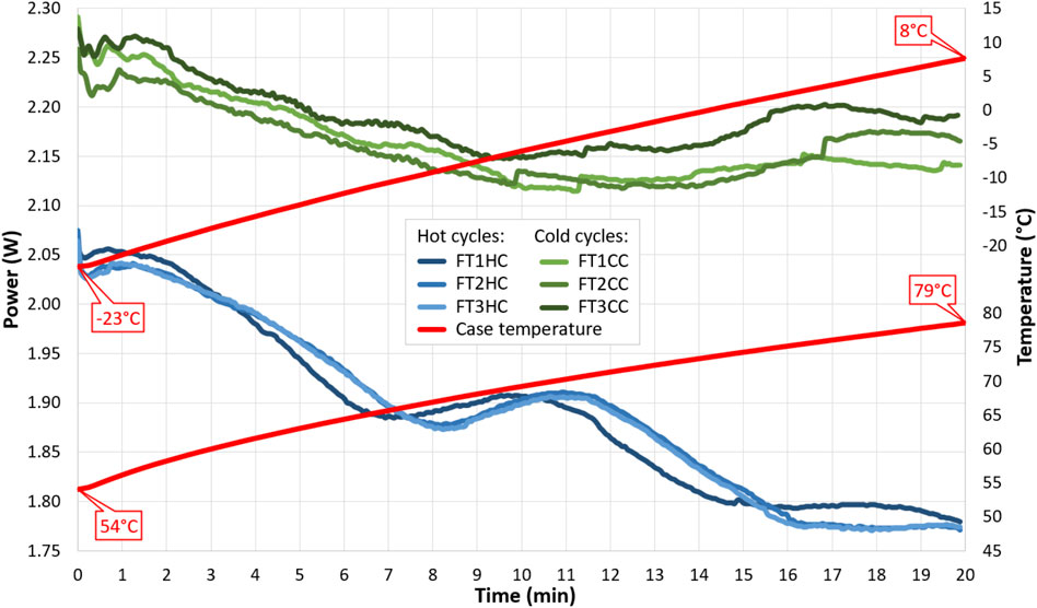
Figure 4. TVAC hot cycles (HC) and cold cycles (CC) for HPA functional tests (FT).
During the test campaign with both modules operating simultaneously, three functional tests were performed, one prior to TVAC and two during TVAC, with the first conducted at room temperature and the second after increasing the temperature to 55°C and stabilizing it for 1 h, with a duration of 30 min. Figure 5 (left) shows this functional test, where it can be seen that after 30 min, the temperature does not stabilize around 90°C with both modules on, as was the case with only the HPA (see Figure 2). In this figure, the HPA and LNA output power were scaled by a factor of 10 and 10,000 respectively for better visibility alongside the HPA + LNA consumed power, although the real initial and final values are shown as well. Care must be taken as the former curves represent optical power while the latter represents electrical power. The HPA’s output power decreases as the module heats up and fails to stabilize, resulting in a significant loss of power due to heat dissipation. Therefore, in the absence of additional heat dissipation or temperature control, when operating both EDFAs simultaneously at high temperatures for longer periods, this must be monitored to avoid damaging the module. One solution would be to position the unit in direct contact with a heat dissipation material with sufficient surface area to absorb the excess heat, such as the CubeSat’s aluminum structure.
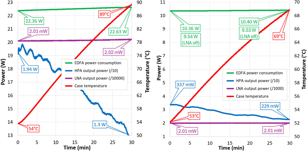
Figure 5. Simultaneous HPA + LNA TVAC hot cycle for max. (left) and min. (right) HPA gain.
For the CubeSOTA mission, where this EDFA will be deployed, the maximum expected link duration is 10 min. In a worst-case scenario, a hot cycle may reach nearly 70°C by the end of the experiment with both modules working at the same time. In this case, the maximum power consumption has been assumed to be 22.5 W and the HPA’s output power is expected to be between 2 W and 1.8 W. Of the total of 22.5 W power consumption, the HPA accounts for approximately 20 W (∼89%), the LNA about 1 W (∼4.4%), and the remaining 1.5 W (∼6.6%) is consumed by the control electronics.
Since the EDFA is the most power-consuming component in a space lasercom terminal, its operation must be adjustable to accommodate potential power constraints. One approach is to disable the LNA and allow only the HPA to support transmit-only communications. At maximum gain, this configuration would consume between 20.1 W and 20.3 W (10-min hot cycle’s initial and final temperature), or ∼0.6 W lower power during a similar cold cycle, as indicated by the test data from Figure 5 (left). Completely turning off the HPA is not considered viable, as even receive-only communications, a minimal transmission is necessary to provide a beacon-like positional reference during the initial acquisition phase of the terminals. Another option is to reduce the HPA’s output power by lowering its gain, whether the LNA is active or not. The HPA gain is controlled by the threshold pump current, with a minimum output power of approximately 25 dBm (∼316 mW). The HPA can produce an output power even below this power, although it is not the amplified input signal in this case.
To evaluate the second approach, two additional 30-min TVAC hot cycles were conducted using the spare EDFA unit at the lowest HPA’s output power to measure the actual power consumption and temperature evolution. Figure 5 (right) presents the result of this campaign, where both the HPA and LNA were active during the first cycle. Since the HPA’s output power is much lower, the module heated up by only 5°C within 10 min (equivalent to the CubeSOTA mission’s link duration), with its output power staying over 300 mW, and the power consumption is 10.4 W, less than half that at full gain (12.1 W lower power). A second cycle was performed with the LNA turned off. However, due to the minimal influence of the LNA on the HPA, the only noticeable difference was a slight reduction in the power consumption, approximately 0.85 W lower than when the LNA was active. The HPA’s output power and case temperature remained nearly identical in both cases.
Finally, an additional measurement campaign was conducted to assess the amplifier’s performance under extremely cold temperatures. For this cold start test, the spare EDFA unit was used again, since the test was destructive. Although the nominal storage temperature range of the electronic components extends down to −40°C, the performance at extreme cold cannot be guaranteed without direct testing. This experiment could not be performed in a vacuum, as the chamber was unable to reach −40°C, its minimum achievable temperature. However, unlike hot cycles, vacuum conditions are not a critical factor in this case, as heat dissipation is not a concern.
Given that −23°C was the minimum initial temperature during TVAC tests, during the cold start test, several cycles were conducted at temperatures below −23°C to determine the minimum operational temperature. In these tests, the EDFA could be powered on even when the case temperature was at −33.75°C as the initial temperature. When enabling the HPA’s pump laser, the module heated up in less than 5 min to −15°C, which is an operational temperature. During this test, the output power was initially unstable, exhibiting significant fluctuations around 2 W before eventually stabilizing. Cold starts below this temperature resulted in module failure. Although it survived a cold start at −40°C, it began to degrade gradually until it ultimately became permanently inoperative.
A final environmental characterization of the EDFA was conducted to accurately determine the input power to the LNA. In this module, input power monitoring at the preamplifier stage was not implemented to prevent an estimated 0.2 dB noise figure degradation. Additionally, conventional sensors typically measure power levels down to approximately −30 dBm, which is insufficient for space communications, where input power may drop to −40 dBm or lower. Nevertheless, estimating the power incident on the amplifier is critical, particularly when evaluating single-mode fiber coupling efficiency for calibration. Assuming APC mode operation and with the output power generally set to 2 mW (its maximum value), the input power level can be inferred based on its relationship with the preamplifier pump driving current, a parameter internally monitored by the LNA.
The relationship between pump current and input power is temperature-dependent, requiring a characterization across a range of temperatures. To this end, the correlation between input power and pump current was measured at room temperature (25°C), as well as under hot (56.77°C) and cold (−20.37°C) conditions. The results showed that in the hot state the pump current increased to 122% of its room temperature value, while at the cold state, it decreases to 90%. Using these three characteristic curves, it is possible to model the dependence of the pump current on both temperature and input power, enabling the calculation of the input power based on known temperature and pump current values.
4 Conclusion
This paper presents the successful development and environmental validation of a compact EDFA with integrated LNA and HPA, distinguished by its miniaturization and high performance, designed for satellite optical communications, and specifically tailored for NICT’s CubeSOTA mission. Environmental testing, including vibration, shock, radiation, and TVAC tests demonstrated the EDFA reliability under space-like conditions with minimal performance degradation across all tests even in extreme conditions. Extensive TVAC testing confirmed the HPA’s temperature dependence and provided insights into the module’s behavior under a wide range of operating conditions. The developed module is, to the best of the authors’ knowledge, the world’s smallest space-qualified EDFA including an LNA and an HPA delivering high output power, serving as a critical enabling technology for the CubeSOTA mission, which aims to demonstrate high data rate optical communications between ultra-small space platforms and ground stations or HAPS.
Data availability statement
The raw data supporting the conclusions of this article will be made available by the authors, without undue reservation.
Author contributions
AC-C: Conceptualization, Investigation, Writing–original draft, Writing–review and editing. KS: Validation, Writing–review and editing. DK: Supervision, Writing–review and editing. HT: Project administration, Writing–review and editing. MT: Funding acquisition, Writing–review and editing.
Funding
The author(s) declare that no financial support was received for the research, authorship, and/or publication of this article.
Conflict of interest
The authors declare that the research was conducted in the absence of any commercial or financial relationships that could be construed as a potential conflict of interest.
Generative AI statement
The author(s) declare that no Generative AI was used in the creation of this manuscript.
Publisher’s note
All claims expressed in this article are solely those of the authors and do not necessarily represent those of their affiliated organizations, or those of the publisher, the editors and the reviewers. Any product that may be evaluated in this article, or claim that may be made by its manufacturer, is not guaranteed or endorsed by the publisher.
References
1. Carrasco-Casado A, Mata-Calvo R. Space optical links for communication networks. In: I Mukherjee, and T Tomkos, editors. Springer handbook of optical networks. Cham: Springer Handbooks (2020). p. 1057–103. doi:10.1007/978-3-030-16250-4_34
2. Carrasco-Casado A, Do PX, Kolev D, Hosonuma T, Shiratama K, Kunimori H, et al. Intersatellite-link demonstration mission between CubeSOTA (LEO CubeSat) and ETS9-HICALI (GEO satellite). Proc IEEE Int Conf Space Opt Syst Appl (Icsos) (2019) 1–5. doi:10.1109/ICSOS45490.2019.8978975
3. Carrasco-Casado A, Takenaka H, Kolev D, Munemasa Y, Kunimori H, Suzuki K, et al. LEO-to-ground optical communications using SOTA (Small Optical TrAnsponder)–Payload verification results and experiments on space quantum communications. Acta Astronautica (2017) 139:377–84. doi:10.1016/j.actaastro.2017.07.030
4. Carrasco-Casado A, Shiratama K, Kolev D, Ono F, Tsuji H, Toyoshima M. Miniaturized multi-platform free-space laser-communication terminals for beyond-5G networks and space applications. MDPI Photon (2024) 11(Issue 6):545. doi:10.3390/photonics11060545
5. Desurvire E. Erbium doped fiber amplifier: principles and applications. New York, NY, USA: Wiley and Sons (2002).
6. Desurvire E. Erbium doped fiber amplifier, device and system developments. New York, NY, USA: Wiley (2002).
7. Edmunds J, Henwood-Moroney L, Hammond N, Prowse E, Hall K, Szemendera L, et al. Miniaturized modules for space-based optical communication. Proc SPIE, Free-Space Laser Commun (2021) XXXIII:17. doi:10.1117/12.2577512
8. Edmunds J, Henwood-Moroney L, Hammond N, Prowse E, Hall K, Szemendera L, et al. Miniaturized optical communications modules for space applications. Proc Int Conf Space Opt (2021) 56. doi:10.1117/12.2599247
9. Girard S, Morana A, Ladaci A, Robin T, Mescia L, Bonnefois J-J, et al. Recent advances in radiation-hardened fiber-based technologies for space applications. J Opt (2018) 20:093001. doi:10.1088/2040-8986/aad271
10. Girard S, Aubry M, Laurent A, Mescia L, Robin T, Balcon N, et al. Recent advances in radiation-hardened fiber-optic amplifiers for space-based laser communications. Photonic Networks and Devices, paper NeTh2C (2021) NeTh2C.4. doi:10.1364/NETWORKS.2021.NeTh2C.4
11. West RH, Dowling S, Lewis R, Sikora E, Wright JV. Effects of ionizing radiation and hydrogen on erbium-doped fiber amplifiers. Opt Mater Reliability Test Benign Adverse Environments (1993) 1791:265–73. doi:10.1117/12.141169
12. Williams GM, Putnam MA, Askins CG, Gingerich ME, Friebele EJ. Radiation-induced coloring of erbium-doped optical fibers. Opt Mater Reliability Test Benign Adverse Environments (1993) 1791:274–83. doi:10.1117/12.141179
13. Williams GM, Friebele EJ. Space radiation effects on erbium-doped fiber devices: sources, amplifiers, and passive measurements. IEEE Trans Nucl Sci (1998) 45(3):1531–6. doi:10.1109/23.685235
14. Ma J, Li M, Tan L-Y, Zhou Y-P, Yu S-Y, Che C. Space radiation effect on EDFA for inter-satellite optical communication. Optik (2010) 121(6):535–8. doi:10.1016/j.ijleo.2008.09.009
15. ISO 15864. Space systems — space systems — general test methods for spacecraft. In: Subsystems and units. Edition 2 (2021). Available online at: https://www.iso.org/standard/78975.html (accessed December 01, 2024).
16. ISO 19683. Space systems — design qualification and acceptance tests of small spacecraft and units. Edition 1 (2017). Available online at: https://www.iso.org/standard/66008.html (accessed December 01, 2024).
Keywords: EDFA, optical amplifier, HPA, LNA, space qualification, cubeSat, CubeSOTA, satellite communications
Citation: Carrasco-Casado A, Shiratama K, Kolev D, Tsuji H and Toyoshima M (2025) Development and environmental validation of a compact EDFA with integrated LNA+HPA for satellite optical communications . Front. Phys. 13:1542043. doi: 10.3389/fphy.2025.1542043
Received: 09 December 2024; Accepted: 27 February 2025;
Published: 14 April 2025.
Edited by:
Abhishek Sharma, National Institute of Technology, Hamirpur, IndiaReviewed by:
Giuseppe Brunetti, Politecnico di Bari, ItalySunita Khichar, Chulalongkorn University, Thailand
Copyright © 2025 Carrasco-Casado, Shiratama, Kolev, Tsuji and Toyoshima. This is an open-access article distributed under the terms of the Creative Commons Attribution License (CC BY). The use, distribution or reproduction in other forums is permitted, provided the original author(s) and the copyright owner(s) are credited and that the original publication in this journal is cited, in accordance with accepted academic practice. No use, distribution or reproduction is permitted which does not comply with these terms.
*Correspondence: Alberto Carrasco-Casado, YWxiZXJ0b0BuaWN0LmdvLmpw