 Xinxiu Xu
 Yanguang Chen
 Junsheng Zhang
- 1Department of Electronic Engineering, Taiyuan Institute of Technology, Taiyuan, China
- 2School of Information Management and Engineering, Shanghai University of Finance and Economics, Shanghai, China
A novel multi-nested anti-resonant fiber for reducing propagation losses in the terahertz band was proposed. The transmission properties of the fibers were analyzed using the finite element method. High-resistivity silicon was used as the fiber material, and the confinement loss of the fiber was reduced by employing eight circumferentially symmetric multi-nested ice-cream-shaped tubes. By optimizing the structural parameters of cladding tubes, the transmission loss of the fiber was effectively reduced. Simulation results show that the total loss of the designed fiber was 1.53 × 10⁻⁴ dB/m. The low loss transmission bandwidth (less than 10–3 dB/m) was 0.26 THz in the 0.6–1.4 THz range. The proposed fiber offered a new possibility for low-loss communication in the terahertz band, demonstrating huge commercial potential.
1 Introduction
The terahertz band (electromagnetic spectrum ranging from 0.1 THz to 10 THz), renowned for its high carrier frequency and substantial communication bandwidth, stands as one of the pivotal technologies capable of accommodating the exigencies for vast-capacity backhaul and ultra-high data transmission stipulated by future 6G mobile communication networks scenarios [1–3]. Terahertz waves exhibit pronounced penetration through non-polar materials owing to their low photon energy, at the same time, they maintain high security in communications, excellent penetrability, and distinctive spectral fingerprinting attributes [4], positioning them as highly promising in disciplines like space science, passive remote sensing, security screening, biomedical imaging, and astronomical observations [5–9]. To exploit the virtues of terahertz technology within the communication realm, it is imperative to depend on high-performance terahertz waveguide technologies for their efficacious transmission. However, the transmission loss in the terahertz band is large thus restricting further development. Therefore, many high-performance structures have been progressively proposed, including metal waveguides, parallel plate waveguides, photonic crystal fibers, and hollow-core fibers (HCFs) [10–13]. Among these, HCFs have undergone rapid development in recent years. Contrary to fibers furnished with solid or porous cores, HCFs facilitate rapid, low-loss propagation of terahertz waves in their core region.
HCFs mainly include hollow-core photonic bandgap (HC-PBGFs) and hollow-core anti-resonant fibers (HC-ARFs). The guiding mechanism of HC-PBGFs involves a periodic arrangement of cladding micro-structured air holes encountering the incident light from the core, which results in multiple scattering phenomena and subsequently causes light interference. This leads to the confinement of the incident light within the core as it cannot pass through the cladding. The transmission mechanism of HC-ARFs is based on a combination of anti-resonant effects and suppression of coupling between the core mode and the cladding mode. HC-ARFs are composed of either a single or multiple layer of cladding tubes. Compared to HC-PBGF, HC-ARFs have a wider transmission bandwidth and lower propagation loss. HC-ARFs feature a series of narrowband/high-loss resonant regions and broadband/low-loss anti-resonant regions. In resonant regions, core modes are phase-matched with cladding modes, leading to high transmission losses, whereas in anti-resonant regions, the transmitted terahertz modes are strictly confined within the air core. With HC-ARFs becoming a focal point of research, the design of the HC-ARFs cladding has diversified, encompassing circle, ellipse or ice-cream shapes [14–17].
Researchers have been optimizing the transmission loss of HC-ARFs through different cladding structure designs. In 2018, S. Gao et al. [18] designed and fabricated an HC-ARF with six non-contacting capillary tubes in the cladding that exhibited a minimal transmission loss of 2 dB/km at a wavelength of 1,512 nm. In 2021, F. Amrani et al. [19] introduced a hybrid cladding HC-ARF composed of a kagome tube lattice and a single layer of round tubes, achieving a minimum transmission loss of 1.6 dB/km at 1,050 nm. Both these different cladding structures of HC-ARFs operate in the infrared range.
Due to the frequency characteristics of the terahertz range, HC-ARFs in the terahertz range generally exhibit higher transmission losses and a narrow effective low-loss transmission bandwidth. This has further spurred researchers to explore new cladding structures and choices of cladding materials. In 2013, Setti et al. [20] fabricated an HC-ARF with a cladding composed of a circular arrangement of dielectric tubes, which achieved lower losses of 0.3 dB/cm at 0.375 THz and 0.16 dB/cm at 0.828 THz. In 2015, Alice et al. [21] reported an HC-ARF based on the TOPAS, with the lowest transmission loss at a working frequency of 1 THz being 0.05 dB/m. In 2020, Sultana et al. [22] reported an HC-ARF incorporating metal wires, which exhibited a minimal loss of 0.0058 dB/m at 1 THz, albeit with limited transmission bandwidth. Moreover, Sultana et al. [23] conducted a comparative analysis using Zeonex on the performance of three types of HC-ARFs: non-nested round tubes, nested round tubes, and adjacent nested round tubes, reporting a transmission loss of 0.055 dB/m at 1 THz.
In this paper, we present the design of HC-ARFs for terahertz transmission, featuring a composed of eight multi-nested ice-cream-shaped tubes. The optimization includes the outer semicircular tube radius, the distance between the center of the circular nested tube and the center of the outer semicircular tube in the nested cladding, the ellipticity of the semi-ellipse, and the radius of the nested tube. High-resistivity silicon (HRS) is employed as the fiber material for the HC-ARFs, reducing the confinement loss to 1.65 × 10⁻⁵ dB/m. Moreover, the total loss is 1.53 × 10⁻⁴ dB/m at 1.0 THz. The low loss transmission bandwidth (less than 10–3 dB/m) is 0.26 THz ranging from 0.6 to 1.4 THz.
2 Fiber structure
Figure 1 illustrates the HC-ARF detailed in the paper, where the cladding is composed of eight multi-nested arranged in a circular symmetry. The external cladding is formed by multi-nested ice-cream-shaped tubes, while the internal cladding tubes are constructed from three parts: semi-elliptical tubes, straight tubes, and circular tubes. Compared with the previous reports, the proposed fiber uses four-layer anti-resonance effect to effectively suppresses confinement loss. The white regions represent air. In HC-ARF, the core inner diameter is denoted as R = 6 mm. The radius of the outer semicircle of the multi-nested ice-cream-shaped tubes is r1 = 1.5 mm. The relationship between ra, a, r1, and t is ra = a × (r1 - t) (where a = 0.67 and t = 0.035 mm is the wall thickness of the cladding tubes). The radius of nested circular tubes is r2 = 0.58 mm. The distance d = 1.05 mm is between the center of the nested circular tubes and semicircle. The nested circular tubes are fused to the protect tube of the HC-ARFs, which has a thickness of T1 = 0.2 mm. In order to accurately model the leakage loss of the fiber [17], we used perfectly-matched layers (PML) in the outermost layer, with a thickness of T2 = 0.6 mm. In the simulation calculations of the anti-resonant fiber, a very fine mesh size of λ/6 is chosen during the grid division step. The possible manufacturing methods of terahertz anti-resonant fiber include stacking [24], extrusion [25] and 3D printing [26]. The stacking method is feasible for the compact cladding tubes structure. The extrusion method is easily to deform the cladding tubes. It is believed that 3D printing method can be used to fabricate our proposed anti-resonant fiber in the future.
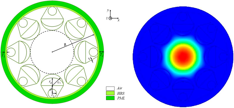
Figure 1. Cross section of the ARF and mode filed distribution.
When the core modes match the cladding modes, it results in higher loss for the light traveling within the core. To achieve lower transmission losses and a broader transmission bandwidth for the fiber, it is necessary to avoid resonance frequencies. When an incident light enters the glass layer from the air, it will be reflected and refracted on the surface of the glass wall, forming an F-P cavity, and the basic principle is to use the interference effect of light. When the phase difference of adjacent transmitted light satisfies the interference phase length, the corresponding resonance frequencies can be obtained, as shown in Equation 1 [27]:
where c represents velocity of light in vacuum, m represents the resonance order, n represents the refractive index of the HRS material, and t represents the wall thickness of the HC-ARFs cladding. The HRS material exhibits a low rate of change in refractive index within the 0.5–4.5 THz range, thus its n is considered a constant value of 3.417. The material absorption coefficient of HRS is only less than 1.5 m-1 in the 0.1–1.5 THz range [28] which is much less than that of 27.6 and 20 m-1 for Topas [21] and Zeonex [29] around 1 THz. Therefore, HRS reduces the effective material loss enabling low-loss transmission. When HC-ARFs operate at 1 THz, the wall thickness that induces resonance is approximately 0.045 mm. To avoid resonance points as much as possible, a wall thickness t = 0.035 mm is chosen, at which the resonance frequency is approximately 1.31 THz.
The transmission loss of HC-ARFs primarily comprises confinement loss and effective material loss. The confinement loss, caused by leakage of the optical field due to the fiber structure during transmission, leads to power loss. It can be minimized through optimization of the fiber structure, and can be represented by Equation 2 [30]:
where, f is the working frequency of HC-ARFs, and
The effective material loss of HC-ARFs stems from the inherent absorption of the material and other factors during transmission, which can be calculated using Equation 3 [30]:
where
3 Results and discussion
3.1 Optimization of the radius r1
The impact of the radius r1 on the transmission loss in optical fibers is investigated. With parameters set at R = 6 mm, t = 0.035 mm, d = 1.05 mm, a = 0.67, and r2 = 0.58 mm, the influence of radius r1 on the loss spectrum is presented as shown in Figure 2a. The minimal losses in the loss spectrum do not significantly differ when r1 = 1.3 mm, 1.5 mm, or 1.6 mm, and the low-loss bandwidth (<10–3 dB/m) demonstrates an initial increase followed by a decreasing trend. In order to further refine the determination of r1, Figure 2b discloses the losses at different radii at an operational frequency of 1 THz. It is evident that, compared to the confinement loss spectrum, the semi-circular radius r1 exerts a relatively smaller impact on the effective material loss, as indicated by the red curve. The blue solid line represents the total loss, and the insert provides an equipotential line diagram of the electric field at different semi-circular radii. As the semi-circular radius r1 increases, the total loss spectrum initially diminishes and then follows an ascending trajectory. This trend is attributed to the increased spacing between adjacent multi-nested ice-cream-shaped tubes when the semi-circular radius r1 is small, which does not readily confine the electric field within the fiber core, resulting in leakage and an increase in total loss, as indicated by the green inset in Figure 2b. Conversely, as the semi-circular radius r1 becomes excessively large, the spacing between the adjacent his trend is attributed to the increased spacing between adjacent multi-nested ice-cream-shaped tubes when the semi-circular radius r1 is small, which does not readily confine the electric field within the fiber core, is too narrow, generating additional resonance effects that lead to an increase in the total loss, as shown by the purple inset in Figure 2b. Optimal transmission and containment of the electric field within the fiber core region occur when the semi-circular radius r1 corresponds precisely with the optimal magnitude for anti-resonance at the operational frequency, thereby minimizing the confinement loss, visualized by the blue inset in Figure 2b. Consequently, a semi-circular radius r1 = 1.5 mm is selected as the optimal value.
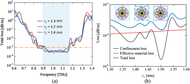
Figure 2. The impact of radius r1 on fiber transmission losses: (a) Total loss versus frequencies for various radii and (b) loss versus radii at f = 1 THz.
3.2 Optimization of the distance d
The impact of distance d on the total loss in optical fibers is studied. Similarly, at parameters R = 6 mm, t = 0.035 mm, r1 = 1.5 mm, a = 0.67, and r2 = 0.58 mm, the effect of distance d on the loss spectrum is depicted in Figure 3a. At d = 1.25 mm, the fiber exhibits its maximum loss and the narrowest low-loss bandwidth. As d increases, the low-loss bandwidth widens, and the minimum total loss gradually decreases before increasing again. The minimum total loss is observed at d = 1.05 mm. To determine the optimal value of d more effectively, Figure 3b presents the losses at different distances d at 1 THz. The effective material loss increases slowly in a monotonic manner, whereas the confinement loss decreases rapidly at first and then levels off, leading to a total loss trend that aligns with that of the confinement loss. Thus, comparing the minimum loss at 1 THz, d = 1.05 mm is selected as the optimal value.
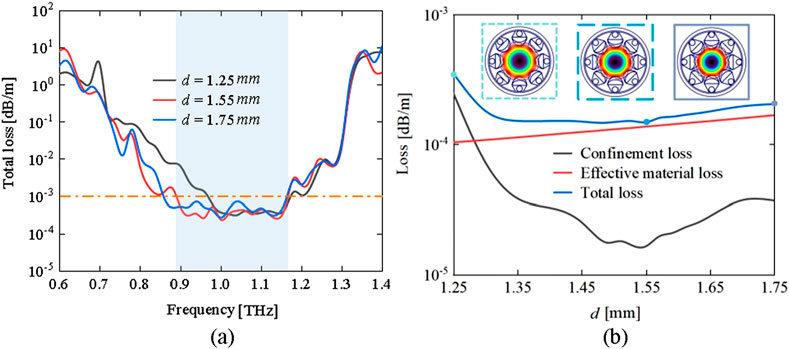
Figure 3. The impact of distance d on fiber transmission losses: (a) Total loss versus frequencies for various distances and (b) loss versus distances at f = 1 THz.
3.3 Optimization of the ellipticity a
The effect of ellipticity a on the transmission performance of optical fibers is presented. With parameters R = 6 mm, t = 0.035 mm, r1 = 1.5 mm, d = 1.05 mm, and r2 = 0.58 mm set, it is found that at higher ellipticities of the semi-elliptical tubes (a = 0.87), the low-loss bandwidth is at its narrowest and the minimum loss is at its largest. As the ellipticity a decreased, for a = 0.67 and 0.87, the difference between the two loss spectra in the low-loss region is relatively small. To further determine the optimal ellipticity a, Figure 4a displays the losses at different ellipticities at the operational frequency of 1 THz. Within the range of 0.47–0.87, the ellipticity almost does not affect the effective material loss, yet it does have a certain impact on the confinement loss, with the total loss exhibiting a trend of decreasing and then increasing. This occurs because when the ellipticity a is too small, it does not contribute to the second-layer anti-resonance. Conversely, as shown in Figure 4b, when the ellipticity a is too large, it interferes with the first-layer anti-resonance. An additional resonance between the inner and outer layers, leading to an increase in transmission loss. Therefore, a = 0.67 is chosen as the optimal parameter.
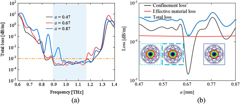
Figure 4. The impact of ellipticity a on fiber transmission losses: (a) Total loss versus frequencies for various ellipticities and (b) loss versus ellipticities at f = 1 THz.
3.4 Optimization of the radius r2
The impact of the radius r2 on the optical fiber transmission performance is explored. With the parameters set at R = 6 mm, t = 0.035 mm, r1 = 1.5 mm, d = 1.05 mm, and a = 0.67, the impact of the radius r2 of the circular nested tube on the loss spectrum is shown in Figure 5a. As the radius r2 of the circular nested tube increases, the optical fiber low-loss transmission bandwidth initially expands and then contracts, yet the total loss among the three curves does not show significant differences. To select an appropriate radius r2 for the circular nested tube, Figure 5b presents the losses as the radius r2 changes at the operating frequency of 1 THz. The effective material loss is almost unaffected, and the fiber confinement loss shows a trend of first decreasing and then increasing. The presence of the circular nested tube radius r2 separates the tail of the multi-nested ice-cream-shaped tubes into two anti-resonance layers. When the radius r2 of the circular nested tube is too small, it does not achieve the optimal anti-resonance effect. When the radius r2 is too large, it generates additional resonance with the structures in the middle of the multi-nested ice-cream-shaped tubes, thereby increasing the total loss. At a circular nested tube radius r2 = 0.58 mm, it is possible to achieve relatively lower total loss at the working frequency of 1THz, while also obtaining a broader low-loss transmission bandwidth across the frequency spectrum.
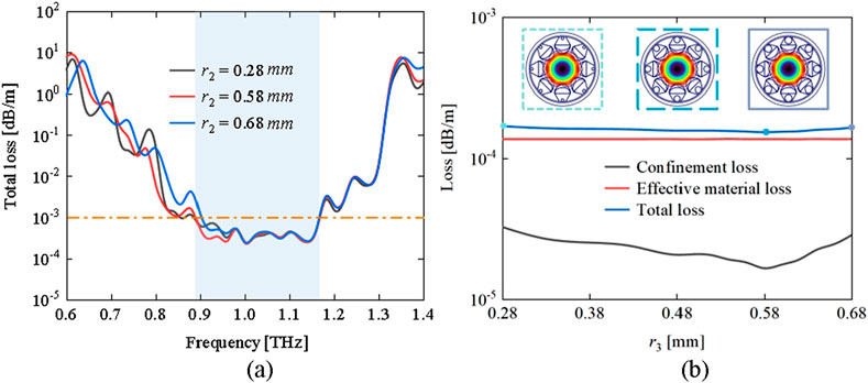
Figure 5. The impact of radius r2 on fiber transmission losses: (a) Total loss versus frequencies for various radii and (b) loss versus radii at f = 1 THz.
3.5 Working bandwidth
Figure 6 presents the fiber transmission loss spectrum in the range of 0.6–1.4 THz under the conditions of R = 6 mm, t = 0.035 mm, r1 = 1.5 mm, d = 1.05 mm, a = 0.67, and r2 = 0.58 mm. As the frequency gradually increases, the fiber confinement loss (black line) exhibits a trend of initially decreasing and then increasing. Notably, at the frequency of 1 THz, the fiber confinement loss reaches its minimum value of 1.65 × 10⁻⁵ dB/m. The effective material loss (red line) remains relatively flat in the low-loss region. Within the whole frequency range (0.6–1.4 THz), the effective material loss is very low, and the total loss is largely determined by the confinement loss. Consequently, at the operational frequency of 1 THz, the fiber minimal total loss is 1.53 × 10⁻⁴ dB/m. The bandwidth with losses less than 10–3 dB/m across the full wave range (0.6–1.4 THz) is 0.26 THz. This ensures that at the operational frequency of 1 THz, the fiber achieves the lowest possible total loss and the widest possible low-loss transmission bandwidth. Table 1 compares the loss properties between our anti-resonant fiber and previously reported anti-resonant fibers. As shown in Table 1, it can be observed that our fiber reduces the effective material loss and suppresses the confinement loss giving rise to an ultra-low total Loss of 10–4 dB/m. The proposed fiber shows improved propagation characteristic as a terahertz waveguide.
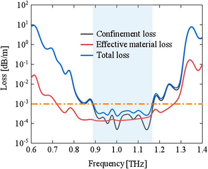
Figure 6. Three types of losses at different frequencies.
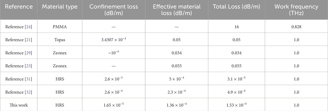
Table 1. Comparison between our anti-resonant fiber and previously reported anti-resonant fibers.
4 Conclusion
This paper proposes a novel multi-nested ice-cream-shaped tubes for HC-ARF in the terahertz band. Utilizing high-resistivity silicon as the fiber material in constructed with the cladding structure, the minimum total loss is as low as 1.53 × 10⁻⁴ dB/m at 1 THz. The transmission bandwidth with losses less than 10–3 dB/m is 0.26 THz in the 0.6–1.4 THz range. The result demonstrates significant application prospects and commercial value.
Data availability statement
The original contributions presented in the study are included in the article/supplementary material, further inquiries can be directed to the corresponding authors.
Author contributions
XX: Writing – original draft. YC: Writing – review and editing. JZ: Writing – original draft.
Funding
The author(s) declare that financial support was received for the research and/or publication of this article. This work was supported in part by the University Science and Technology Innovation Project of Shanxi Province under Grant 2023L359.
Conflict of interest
The authors declare that the research was conducted in the absence of any commercial or financial relationships that could be construed as a potential conflict of interest.
Generative AI statement
The author(s) declare that no Generative AI was used in the creation of this manuscript.
Publisher’s note
All claims expressed in this article are solely those of the authors and do not necessarily represent those of their affiliated organizations, or those of the publisher, the editors and the reviewers. Any product that may be evaluated in this article, or claim that may be made by its manufacturer, is not guaranteed or endorsed by the publisher.
References
1. Akyildiz IF, Jornet JM, Han C. TeraNets: ultra-broadband communication networks in the terahertz band. IEEE Wireless Commun (2014) 21:130–5. doi:10.1109/mwc.2014.6882305
2. Moon S, Kim E, Sung M, Rha HY, Lee ES, Lee IM, et al. 6G indoor network enabled by photonics- and electronics-based sub-THz technology. J Lightwave Technology (2021) 40:499–510. doi:10.1109/jlt.2021.3113898
3. Yu J, Wang Y, Ding J. Broadband photon-assisted terahertz communication and sensing. In: European conference on optical communication (2022). 1–4.
4. Islam S, Cordeiro CMB, Franco MAR, Sultana J, Cruz ALS, Abbott D. Terahertz optical fibers [Invited]. Opt express (2020) 28(11):16089–117. doi:10.1364/oe.389999
5. Siegel P. THz instruments for space. IEEE Trans Antennas Propagation (2007) 55:2957–65. doi:10.1109/tap.2007.908557
6. Kellarev A, Sheffer D. Terahertz remote sensing. In: Terahertz physics, devices, and systems V, 8023. SPIE: Advance Applications in Industry and Defense (2011). p. 80230N. doi:10.1117/12.883109
7. Momiyama H, Sasaki Y, Yoshimine I, Nagano S, Yuasa T, Otani C. Improvement of the depth resolution of swept-source THz-OCT for non-destructive inspection. Opt Express (2020) 28(8):12279–93. doi:10.1364/oe.386680
8. Pickwell E, Wallace VP. Biomedical applications of terahertz technology. J Phys D: Appl Phys (2006) 39(17):R301–10. doi:10.1088/0022-3727/39/17/r01
9. Kulesa C. Terahertz spectroscopy for astronomy: from comets to cosmology. IEEE Trans Terahertz Sci Technology (2011) 1(1):232–40. doi:10.1109/tthz.2011.2159648
10. Harrington JA, George R, Pedersen P, Mueller E. Hollow polycarbonate waveguides with inner Cu coatings for delivery of terahertz radiation. Opt Express (2004) 12(21):5263–8. doi:10.1364/opex.12.005263
11. Lee ES, So JK, Park GS, Kim D, Kee CS, Jeon TI. Terahertz band gaps induced by metal grooves inside parallel-plate waveguides. Opt express (2012) 20(6):6116–23. doi:10.1364/oe.20.006116
12. Yakasai IK, Abas PE, Suhaimi H, Begum F. Low loss and highly birefringent photonic crystal fibre for terahertz applications. Optik (2020) 206:164321. doi:10.1016/j.ijleo.2020.164321
13. Ponseca JCS, Pobre R, Estacio E, Sarukura N, Argyros A, Large MC, et al. Transmission of terahertz radiation using a microstructured polymer optical fiber. Opt Lett (2008) 33(9):902–4. doi:10.1364/ol.33.000902
14. Wu D, Yu F, Liao M. Understanding the material loss of anti-resonant hollow-core fibers. Opt Express (2020) 28(8):11840–51. doi:10.1364/oe.380847
15. Yang Y. Parametric optimization for low loss negative curvature hollow core fiber with elliptical tube. J Lightwave Technology (2022) 41(1):293–300. doi:10.1109/JLT.2022.3211291
16. Deng A, Hasan I, Wang Y, Chang W. Analyzing mode index mismatch and field overlap for light guidance in negative-curvature fibers. Opt Express (2020) 28(19):27974–88. doi:10.1364/oe.400267
17. Habib S, Antonio-Lopez JE, Markos C, Schülzgen A, Amezcua-Correa R. Single-mode, low loss hollow-core anti-resonant fiber designs. Opt Express (2019) 27(4):3824–36. doi:10.1364/oe.27.003824
18. Gao S, Wang Y, Ding W, Jiang D, Gu S, Zhang X, et al. Hollow-core conjoined-tube negative-curvature fibre with ultralow loss. Nat Commun (2018) 9(1):2828. doi:10.1038/s41467-018-05225-1
19. Amrani F, Osório JH, Delahaye F, Giovanardi F, Vincetti L, Debord B, et al. Low-loss single-mode hybrid-lattice hollow-core photonic-crystal fibre. Light: Sci and Appl (2021) 10(1):7. doi:10.1038/s41377-020-00457-7
20. Setti V, Vincetti L, Argyros A. Flexible tube lattice fibers for terahertz applications. Opt Express (2013) 21(3):3388–99. doi:10.1364/oe.21.003388
21. Hasanuzzaman GKM, Iezekiel S, Markos C, Habib MS. Hollow-core fiber with nested anti-resonant tubes for low-loss THz guidance. Opt Commun (2018) 426:477–82. doi:10.1016/j.optcom.2018.05.071
22. Sultana J, Islam MS, Cordeiro CMB, Dinovitser A, Kaushik M, W.-H. Ng B, et al. Terahertz hollow core antiresonant fiber with metamaterial cladding. Fibers (2020) 8(2):14. doi:10.3390/fib8020014
23. Sultana J, Islam S, Cordeiro CMB, Habib S, Dinovitser A, Ng BW, et al. Exploring low loss and single mode in antiresonant tube lattice terahertz fibers. IEEE Access (2020) 8:113309–17. doi:10.1109/access.2020.3003035
24. Setti V, Vincetti L, Argyros A. Flexible tube lattice fibers for terahertz applications. Opt Express (2013) 21(3):3388–99. doi:10.1364/oe.21.003388
25. Talataisong W, Gorecki J, Putten LDV. Hollow-core antiresonant terahertz fiber-based TOPAS extruded from a 3D printer using a metal 3D printed nozzle. Photon Res (2021) 9(8):1513–21. doi:10.1364/PRJ.420672
26. Cruz ALS, Cordeiro CMB, Franco MAR. 3D printed hollow-core terahertz fibers. Fibers (2018) 6(30):6030043. doi:10.3390/fib6030043
27 . Liu Q, Sun G, Sun Y, Yao X, Lv J, Liu W, et al. Negative curvature fiber (NCF) polarization filter with large polarization loss ratio and ultralow loss in the terahertz range. Opt Commun (2024) 568:130736. doi:10.1016/j.optcom.2024.130736
28. Dai J, Zhang J, Zhang W, Grischkowsky D. Terahertz time-domain spectroscopy characterization of the far-infrared absorption and index of refraction of high-resistivity, float-zone silicon. J Opt Soc America B (2004) 21(7):1379–86. doi:10.1364/josab.21.001379
29. Mollah A, Habib S, Habib S. Novel hollow-core asymmetric conjoined-tube anti-resonant fiber for low-loss THz wave guidance. OSA Continuum (2020) 3(5):1169–76. doi:10.1364/osac.393189
30. Liu Q, Sun G, Mu H, Liu W, Lv T, Ma C, et al. Hybrid nested negative curvature fiber with ultra-low-loss in the terahertz band. Infrared Phys Technol (2024) 136:105003. doi:10.1016/j.infrared.2023.105003
31. Sun G, Liu Q, Mu H, Sun Y, Wang S, Han M, et al. Anti-resonant fiber with nested U-shape tubes for low-loss terahertz waveguides. Opt Laser Technol (2023) 163:109424. doi:10.1016/j.optlastec.2023.109424
Keywords: terahertz transmission, hollow-core anti-resonant fiber, nMulti-nested ice-cream-shaped tubes, confinement loss, finite element method
Citation: Xu X, Chen Y and Zhang J (2025) Multi-nested anti-resonant fiber with ice-cream-shaped tubes for terahertz communications. Front. Phys. 13:1560320. doi: 10.3389/fphy.2025.1560320
Received: 14 January 2025; Accepted: 31 March 2025;
Published: 28 April 2025.
Edited by:
Rui Min, Beijing Normal University, ChinaReviewed by:
Murugan Senthil Mani Rajan, Anna University, IndiaQisheng Wang, Nanchang University, China
Copyright © 2025 Xu, Chen and Zhang. This is an open-access article distributed under the terms of the Creative Commons Attribution License (CC BY). The use, distribution or reproduction in other forums is permitted, provided the original author(s) and the copyright owner(s) are credited and that the original publication in this journal is cited, in accordance with accepted academic practice. No use, distribution or reproduction is permitted which does not comply with these terms.
*Correspondence: Xinxiu Xu, eHV4eEB0aXQuZWR1LmNu; Junsheng Zhang, emhhbmdqc0B0aXQuZWR1LmNu