 Lihao Yao1,2
 Bin Fan3*
 Honglei Qin1Deyong Xian2Mengli Wang2Boyun Gu4Sumin Chen1,5Changhong Wang1,2Xuyu Wang2Jiemin Shen2Dongfang Jiang2Heng Wei2Haoyuan Yu2Bingjie Liu2Shuai Shao6
- 1School of Electronics and Information Engineering, Beihang University, Beijing, China
- 2Beijing Satellite Navigation Center, Beijing, China
- 3Department of Information Engineering, Army Academy of Artillery and Air Defense, Hefei, China
- 4Beijing Institute of Technology, Beijing, China
- 5COMAC Shanghai Aircraft Design and Research Institute, Shanghai, China
- 6Shaanxi Datang Gas Safety Technology Co., LTD, Beijing, China
Signal-of-Opportunity (SOP) navigation based on Low-Earth-Orbit (LEO) satellite constellations has increasingly become a research hotspot. Due to the large number of LEO satellites, wide spectrum coverage, and strong signal power, LEO satellite Signal-of-Opportunity (LEO-SOP) inherently possess strong anti-jamming capabilities. However, there has been limited in-depth research on the overall system-level anti-jamming capability of LEO-SOP. This paper reviews the current state of research on LEO-SOP and anti-jamming technologies, introduces the principles of LEO-SOP Doppler-based positioning and receiver operation, and analyzes the system-level anti-jamming capability of LEO-SOP. Additionally, it explores the key challenges in the development of LEO-SOP anti-jamming technologies and discusses future research directions. This study aims to provide insights into the development prospects of LEO-SOP anti-jamming technologies, promote further research and development efforts, and establish a solid technical foundation for the secure application of LEO-SOP. Ultimately, ensuring the integrity and resilience of LEO-SOP systems against complex threats.
1 Introduction
The acquisition of location information based on satellite navigation plays an extremely important role in today’s technological development and social progress. Among these, positioning technology based on the Global Navigation Satellite System (GNSS) is the primary method for obtaining location information via satellite navigation. The current major GNSS systems include the United States’ Global Positioning System (GPS), Russia’s GLONASS, Europe’s Galileo, and China’s BeiDou Navigation Satellite System (BDS). With the development of GNSS, it is becoming a crucial infrastructure for national informatization construction, providing Positioning, Navigation, and Timing (PNT) service information for a variety of applications [1–5]. It plays a significant role in daily life, scientific research, and military applications. However, as the use of GNSS deepens, its inherent shortcomings have gradually become apparent, including low signal power upon reaching the ground, single frequency points, high construction and maintenance costs, and significant risks such as susceptibility to malicious interference leading to service unavailability during peacetime or tense situations [6–8]. How to overcome and compensate for these GNSS shortcomings, especially in environments where GNSS services fail, and still independently provide reliable and high-precision PNT services has become a focus of future development [9, 10]. Currently, countries are actively building resilient PNT systems to ensure that military equipment can still achieve accurate positioning when GNSS performance is degraded or denied. In the PNT technology development roadmap released by the U.S. Department of Defense in 2020, it mentioned the use of Signal-of-Opportunity (SOP) for absolute positioning, thereby supplementing GPS positioning functions and enhancing GPS availability and robustness.
SOP positioning refers to a technology that utilizes all perceivable non-navigation and non-positioning application information such as sound, light, electricity, magnetism, and force for positioning. Due to the abundant presence of various radio signals in space, the current research primarily focuses on radio SOP. SOP typically includes terrestrial and space-based radio Signal-of-Opportunity. Terrestrial SOP has limited coverage and struggles to achieve global seamless coverage in areas such as deserts, oceans, and polar regions [11–13]. Space-based SOP mainly refers to signals transmitted by non-navigation/non-cooperative satellites. With the recent vigorous development and construction of Low-Earth-Orbit (LEO) satellites by various countries, space-based LEO satellite SOP (LEO-SOP) has gradually been applied in navigation and positioning as a primary space-based SOP [14]. Unlike GNSS, LEO satellites orbit at altitudes between 500 km and 2,000 km, resulting in higher signal power upon reaching the ground [15]. Additionally, the large number of LEO satellites means their signals cover a wide range of frequencies, with many available frequency points. Currently, the published satellite signal frequency bands can cover from 100 MHz to 40 GHz [16]. These characteristics ensure that LEO satellite signals have stronger anti-jamming capabilities compared to GNSS. Finally, using LEO-SOP for positioning does not require additional construction, resulting in lower costs. Therefore, positioning technology based on LEO-SOP leverages existing satellite resources and requires only minimal financial investment to meet positioning service needs, providing an effective backup to GNSS.
Currently, LEO constellations can be categorized into three types based on their construction maturity: ① Traditional LEO constellations that have been completed and networked, primarily consisting of narrowband communication satellite constellations. Examples include the United States’ Iridium, Globalstar, Swarm SpaceBEE, France’s Argos, and the jointly constructed Orbcomm satellites by the United States and Canada. These operate in frequency ranges from VHF to L-band and mainly provide narrowband communication services to the ground [17–19]. ② LEO constellations that have been planned and have undergone significant satellite launches, primarily broadband internet satellite systems, mainly using Ku-band and higher frequency signals. The main goal is to provide broadband internet access services to the ground through large-scale LEO constellations, achieving global seamless coverage through satellite networking. Currently under construction are the UK’s OneWeb and the United States’ Starlink constellations. OneWeb has completed the launch and networking of its first-generation internet constellation, with 618 satellites in orbit at an operational altitude of 1,200 km. As of March 2025, Starlink has successfully launched over 6,000 satellites, with 5,614 still operational in orbit, making it the largest LEO internet constellation currently in service. These satellites are primarily deployed to build a global LEO satellite internet network, providing coverage for fixed, mobile, maritime, and aeronautical users. By the end of 2024, the system had delivered satellite internet services to over 4 million users across nearly 100 countries. SpaceX is accelerating Starlink satellite deployment through its Starship program. On 6 March 2025, the eighth test flight of Starship was completed, successfully validating its payload deployment capability, including the release of four Starlink satellite simulators. The test also demonstrated upgraded atmospheric re-entry technology and propulsion systems, laying the groundwork for future large-scale satellite deployment [20]. ③ Constellations that have been planned but have only launched a small number of satellites, with functions and frequency bands similar to the aforementioned broadband internet constellations. These include Canada’s Telesat and China’s StarNet, Xingyun Project, Tianqi Satellites, and Galaxy Aerospace, among others. Additionally, some independent LEO satellite navigation and timing systems are being constructed to enhance the anti-jamming capabilities of traditional GNSS, including China’s Weili Space and the United States’ Pulsar. According to the UCS satellite database, LEO satellites account for nearly 90% of all operational satellites in orbit. In the coming years, the number of global LEO satellites in orbit is expected to exceed 22,000, providing a vast number of radiation sources for LEO satellite positioning, making it a key research subject for signal of opportunity positioning [21]. The current major LEO satellite constellations domestically are shown in Table 1.
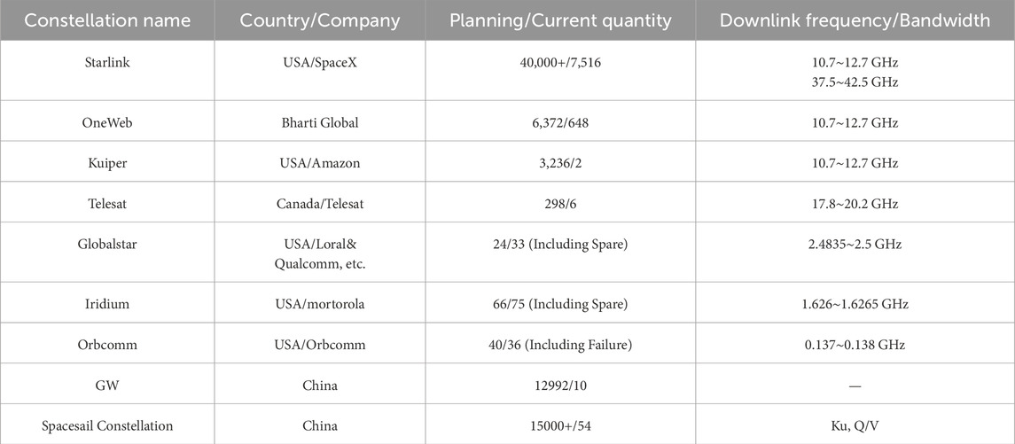
Table 1. Current status and future plans of LEO satellite development (as of January 2025).
This paper reviews the research on LEO-SOP and anti-jamming technologies and analyzes the system-level anti-jamming capability of LEO-SOP while exploring its future development challenges. The remainder of this paper is structured as follows: Section 2 reviews the current research status of LEO-SOP and anti-jamming technologies. Section 3 introduces the Doppler-based positioning principle of LEO-SOP and the receiver operation process. Section 4 analyzes the system-level anti-jamming capability of LEO-SOP. Section 5 discusses the challenges and prospects of LEO-SOP anti-jamming development. Finally, Section 6 summarizes the discussions above.
To facilitate the reader’s understanding, Table 2 lists some important abbreviations involved in this paper, with specific explanations provided in Table 2.
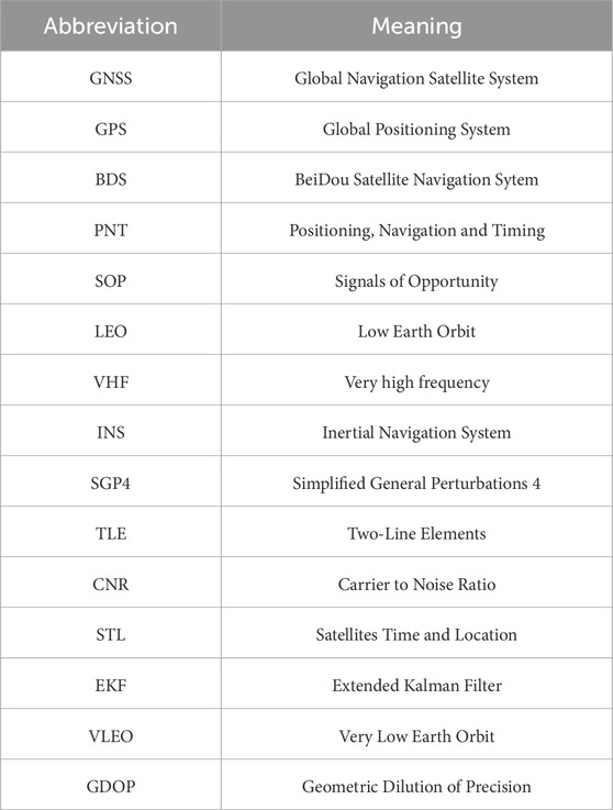
Table 2. Abbreviations table.
2 Current research status of related technologies in domestic and international contexts
This section reviews and summarizes national-level plans for space-based SOP positioning, the development of LEO-SOP positioning technology, and the current state of anti-jamming research. This provides a theoretical foundation for the subsequent analysis of anti-jamming capabilities.
2.1 National PNT strategy
The current national plans that have been announced for positioning using SOP mainly include the United States’ All Source Positioning and Navigation (ASPN) project, the United Kingdom’s Navigation Signal of Opportunity (NavSOP) system, the European Space Agency’s Navigation Innovation Support Program (NAVISP), and the Future Navigation (FutureNAV) plan.
①ASPN Project: In 2010, the Defense Advanced Research Projects Agency (DARPA) of the United States proposed a research plan to combine inertial navigation systems (INS) with non-navigation SOP from satellites, broadcasts, and other sources to achieve positioning. This project has achieved significant results in both military and civilian fields. In 2021, the United States released its Space Policy Directive-7 (SPD-7), also known as the U.S. National Space-Based Positioning, Navigation, and Timing (PNT) Policy. The policy focuses on improving GPS performance while reiterating concerns about over-reliance on PNT data systems. It emphasizes the need for multi-source PNT that can supplement or replace GPS when necessary. The policy also highlights the future development of LEO communication constellations, which will be integrated into the PNT system to enhance the robustness and reliability of GNSS signals, contributing to the establishment of an integrated PNT system. In April and November 2021, the U.S. Air Force, in collaboration with the Naval Surface Warfare Center, successfully completed flight tests of a new type of PNT “agile pod.” The signal sources included SOP, which validated the ability to provide PNT capabilities in GPS-denied environments. In June 2021, the U.S. Army signed a contract with Iridium to develop payloads that can be hosted on LEO satellites for broadcasting timing or positioning signals. This initiative is considered a backup solution for the GPS system.
②NavSOP System: In 2012, BAE Systems developed a new type of positioning system that does not rely on GNSS, aiming to provide an alternative solution for positioning in complex environments. The core of this system is to utilize SOP such as mobile phone signals, Wi-Fi, broadcast signals, and TV tower signals to achieve a positioning system that is highly resistant to interference, low-cost, and flexible in application. In October 2020, the UK Space Agency proposed the Space-Based Positioning, Navigation, and Timing Program (SBPP). This program is based on a space-based PNT system composed of multiple satellites, aiming to build a system with independent PNT capabilities. It provides high-precision and highly reliable positioning and timing services for various fields such as defense, infrastructure, intelligent transportation, and emergency rescue, reducing dependence on existing GNSS.
③NAVISP Plan: In 2016, the European Space Agency (ESA) introduced the NAVISP plan, aiming to provide better solutions for Europe’s PNT systems by supporting new technologies, research, and applications. The plan includes enhancing the satellite navigation services of the Galileo system using LEO satellites. In October 2021, an ESA-funded project known as “Next-Generation Network-Aided PNT Assurance” utilized encrypted signals from Iridium, LTE/5G, and GNSS as potential SOPs to enhance PNT functionality. In February 2024, a machine learning-based SOP navigation plan was proposed. This plan integrates terrestrial SOP signals such as 5G or Wi-Fi with space-based SOP signals from LEO satellites and GNSS signals to overcome the limitations of traditional GNSS.
④FutureNAV Plan: In 2022, ESA introduced the FutureNAV plan, building on the foundation of the NAVISP program. The FutureNAV plan aims to address the increasingly complex needs for PNT and to enhance Europe’s independence and technological innovation capabilities in the global navigation domain. The plan promotes advancements in PNT systems through the application of LEO satellites, innovative navigation signal design, and enhanced anti-jamming and security features, providing support for applications across multiple industries.
All of the aforementioned national plans have incorporated space-based SOP based on LEO satellites into the research of new-generation PNT systems. Corresponding experiments with weapons and equipment have been conducted, as well as performance validation in typical environmental scenarios. These efforts have demonstrated the viability and feasibility of positioning technology using space-based LEO satellite SOP. After several years of research by relevant institutions both domestically and internationally, a large number of phased achievements have been made in the field of LEO-SOP positioning. The following section will summarize the current research status in this field both domestically and internationally.
2.2 Current research status of LEO-SOP positioning technology
The signals from LEO satellites are generally non-navigation/non-cooperative signals, which either do not contain or make it difficult to extract navigation information. Therefore, the current research on LEO-SOP positioning technology mainly focuses on analyzing the signal structure of LEO satellites to extract Doppler measurements for positioning.
The earliest research on positioning using LEO satellites appeared in 1998. This study used one or two Globalstar satellites to determine the location of a user terminal, achieving instantaneous user positioning with a horizontal position accuracy better than 10 km [22]. In 1999, Levanon N from Tel Aviv University in Israel proposed an instantaneous positioning method using a single LEO satellite. This method measured the distance between the satellite and the user terminal, as well as the Doppler frequency, and assumed that the user terminal was on the Earth’s surface to achieve instantaneous user positioning [23]. The concept of SOP positioning and related research began after 2000. The term SOP first appeared in a 2005 graduate thesis from the Air Force Institute of Technology at the United States Air Force University. This thesis primarily focused on the study of ground-based SOP for positioning, such as AM, FM, WiFi, and OFDM [24].
Traditional LEO-SOP positioning primarily relies on single-constellation LEO-SOP positioning technology. Since LEO satellites are not designed for navigation purposes, their visibility and constellation configurations are generally poor. In recent years, to further enhance positioning accuracy and system availability, various positioning technologies developed based on single-constellation LEO-SOP positioning have been extensively studied. These newly developed technologies reduce errors generated during the positioning process through different approaches, such as: multi-constellation LEO-SOP positioning technology, which integrates multiple constellations to overcome the limitations of single-constellation satellite selection; LEO-SOP differential positioning technology, which eliminates orbital errors caused by extrapolation using the Simplified General Perturbations 4 (SGP4) model and Two-Line Elements (TLE) in traditional techniques through differential methods; and LEO-SOP/INS integrated positioning technology, which combines LEO-SOP with INS to ensure real-time dynamic positioning, as the low output rate of LEO-SOP navigation measurements makes it difficult to meet real-time dynamic positioning requirements. Below, we will summarize the research status at home and abroad from four aspects: single-constellation LEO-SOP positioning technology, multi-constellation LEO-SOP joint positioning technology, LEO-SOP differential positioning technology, and LEO-SOP/INS integrated positioning technology.
2.2.1 Single-constellation LEO-SOP positioning technology
In the field of single-constellation LEO-SOP positioning technology, the main research institutions include the team of Qin H from Beihang University in China and the team of Kassas Z from the University of California in the United States. In the early stages of research, the focus was primarily on the Iridium and Orbcomm constellations, which are typical LEO constellations. In recent years, with the development of the Starlink and Globalstar constellations, research on these systems has also garnered widespread attention.
In 2019, the team of Qin H from Beihang University first established a receiving and positioning system based on Iridium satellite signals. By combining TLE orbital information with Doppler measurements, the system achieved positioning. The experimental results showed that after accumulating Doppler measurements from 7 Iridium satellites over 30 min, the positioning accuracy was better than 200 m with the aid of elevation information [25]. In 2020, building on their previous research, the team further developed positioning technology for Iridium signals in weak signal environments. They proposed a secondary square cumulative instantaneous Doppler estimation algorithm to enhance the Doppler estimation capability of weak Iridium signals. The experimental results indicated that the proposed method could improve positioning performance in weak signal environments, thereby enhancing the environmental adaptability of Iridium positioning [26]. In 2023, the team of Qin H established an orbital error equivalent Doppler measurement error model for LEO satellites. Based on the model analysis, they proposed a two-step improved positioning method using orbital error compensation and weighting to suppress the impact of orbital errors. The method was validated using real signals from Iridium and Orbcomm satellites, and the results showed that the positioning accuracy of the proposed method was significantly higher than that of existing methods [27]. In the same year, the team analyzed the pilot signal structure of Globalstar and obtained Doppler measurements through fourth-order processing for despreading. The experiments demonstrated that static positioning with a horizontal error of less than 300 m could be achieved using signals from two Globalstar satellites [28]. In 2024, addressing the issue of receiver hardware limitations that prevent the full utilization of all visible satellite information, the team proposed a fast clustering satellite selection algorithm. This algorithm aims to achieve higher performance positioning results with a limited number of satellites. The method was validated using real Starlink signals, and the results showed that compared to traditional methods, the positioning error was stably reduced by more than 45% [29].
In 2019, the Kassas Z team at the University of California, USA, developed a positioning system based on Orbcomm satellites and proposed a receiver architecture for acquisition and tracking using an Extended Kalman Filter (EKF). Experimental results demonstrated that the static positioning accuracy, utilizing Doppler measurements from two Orbcomm satellites, could reach 360 m [30]. In 2021, the team established a Starlink signal model and introduced an adaptive carrier phase tracking algorithm to track Starlink signals. The experiment successfully extracted carrier phase measurements from six Starlink satellites, achieving a static positioning accuracy of 33.5 m [31]. In 2023, the Kassas Z team proposed a blind receiver architecture that captures satellite measurements through sequential generalized likelihood ratio testing. The experiment tracked six Starlink satellites, with three transmitting single-tone signals and the other three transmitting OFDM-like signals. The results showed a static positioning horizontal error of 6.5 m [32].
2.2.2 Multi-constellation LEO-SOP positioning technology
When using a single LEO satellite constellation for positioning, issues such as insufficient visible satellites and poor satellite geometry may arise. These problems can be effectively addressed through multi-constellation LEO-SOP joint positioning. In the field of multi-constellation LEO-SOP joint positioning technology, the main research institutions include the Farhangian F team at the University of Quebec in Canada, the Kassas Z team at the University of California in the United States, and the Qin H team at Beihang University in China. Current practical testing has primarily focused on Iridium/Orbcomm joint positioning. Figure 1 illustrates the schematic diagram of multi-constellation LEO-SOP integrated positioning.
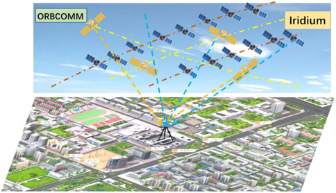
Figure 1. Schematic diagram of multi-constellation LEO-SOP integrated positioning.
In 2020, the Farhangian F team at the University of Quebec in Canada pioneered the design of a multi-constellation software receiver to extract Doppler measurements from LEO satellites. By tracking and collecting Doppler data from one Iridium satellite and two Orbcomm satellites, and utilizing EKF for positioning, the results demonstrated that the dual-constellation positioning accuracy reached 132 m. This represented a 72% improvement compared to single-constellation positioning accuracy [33].
In 2021, the Kassas Z team at the University of California, USA, proposed a receiver architecture suitable for processing signals from Orbcomm and Iridium satellites. By collecting data from one Orbcomm satellite and four Iridium satellites over a period of 7 min and using EKF for positioning, they achieved a horizontal positioning accuracy of 22.7 m [34]. In 2023, the team introduced a novel blind spectral estimation method for blind beacon estimation, Doppler tracking, and SOP positioning. Utilizing signals from two OneWeb satellites, four Starlink satellites, one Iridium satellite, and one Orbcomm satellite, they achieved a three-dimensional positioning error of 5.8 m and a two-dimensional positioning error of 5.1 m within 560 s [35, 36].
In the aforementioned multi-constellation joint positioning studies, the differences in measurement noise between different constellations were not taken into account, which could potentially degrade positioning performance to some extent. To address this issue, in 2022, the Qin H team at Beihang University proposed an Iridium/Orbcomm dual-constellation fusion positioning scheme based on the Helmert variance component weight estimation algorithm. This approach effectively improves the accuracy of weight allocation between different constellations. Experimental results demonstrate that the proposed method significantly enhances the performance of multi-constellation fusion positioning [37].
2.2.3 LEO-SOP differential positioning technology
LEO satellites face challenges in obtaining precise orbital parameter information, and atmospheric delay errors also significantly impact LEO satellite positioning. Differential positioning technology can mitigate the effects of orbital errors and atmospheric delay errors on positioning, thereby further enhancing the accuracy of LEO satellite SOP positioning. Figure 2 illustrates the schematic diagram of the LEO-SOP differential positioning process.
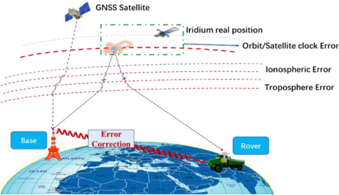
Figure 2. Schematic diagram of LEO-SOP differential positioning process.
In 2019, the Kassas Z team at the University of California proposed a differential positioning framework based on carrier phase and validated it using Orbcomm signals. The results showed a positioning accuracy of 11.93 m, representing a significant improvement over single-point positioning [38]. In 2020, the team further introduced a differential carrier phase navigation framework utilizing signals from massive LEO satellite constellations. They derived the joint probability density function of LEO satellite azimuth and elevation angles to enhance navigation performance. Experimental results demonstrated that the Root Mean Square Error (RMSE) reached 14.8 m within 2 min [39, 40]. By 2022, the team developed a receiver capable of capturing and tracking the Doppler frequency of Starlink satellites. They designed a Kalman filter-based chirp parameter tracking algorithm and performed differential positioning using Doppler frequency. With baselines of 1 km and 9 m, the positioning errors were 5.6 m and 2.6 m, respectively [41].
In 2022, the Qin H team at Beihang University proposed a LEO-SOP Doppler differential positioning framework. To address the issue of reduced positioning accuracy caused by inconsistent spatiotemporal references in long-baseline differential positioning, the team introduced a signal transmission time estimation algorithm based on Maximum Likelihood Estimation (MLE), which further improved the accuracy of static differential positioning [42]. In 2023, to enhance the performance of long-baseline differential positioning, the team proposed a space-based SOP long-baseline differential positioning algorithm based on baseline projection vector geometric model correction. This algorithm mitigates the impact of baseline length on positioning performance and significantly improves the accuracy of long-baseline differential positioning. Experimental results demonstrate that, with a baseline length of 20 km, a positioning accuracy of 30 m can be achieved using 20 min of Iridium satellite signals, representing an improvement of over 70% compared to non-differential positioning accuracy [43]. In 2024, the team addressed the issue of significant errors in traditional Doppler differential positioning under long baselines by proposing a Doppler differential positioning algorithm based on line-of-sight vector correction. Experimental results show that, with a baseline length of 50 km, the positioning accuracy using Iridium satellite signals is better than 10 m [44].
2.2.4 LEO-SOP/INS integrated positioning technology
The output rate of LEO satellite SOP navigation measurements is relatively low, making it difficult to meet the requirements for real-time dynamic positioning. Additionally, the limited number of mature LEO satellite constellations available for navigation results in insufficient instantaneous visibility for the carrier, preventing instantaneous positioning. Therefore, integrating LEO-SOP with INS is necessary to ensure the real-time performance of dynamic positioning, thereby enhancing the system’s availability.
In 2019, the Kassas Z team at the University of California utilized Orbcomm Doppler measurements to assist INS for positioning. Experimental results showed that, when using two Orbcomm satellites for positioning, the final positioning error after 30 s of GNSS unavailability was reduced from 31.7 m to 8.9 m [45]. In the same year, the Benzerrouk team in Canada proposed a multivariate orthogonal Kalman filtering method to integrate Iridium Doppler measurements with INS and tested it using airborne data. The experimental results indicated that the dynamic positioning accuracy ranged between 200 m and 1,000 m [46].
In 2022, researchers at the University of Quebec in Canada combined LEO satellite measurements with INS using a second-order EKF. They conducted vehicle-based experiments using actual Iridium and Orbcomm signals, as well as simulated Globalstar Doppler measurements, integrated with an INS with a drift rate of 10°/h. The results demonstrated that the positioning accuracy was better than 10 m within 150 s [47].
In 2023, the Qin H team at Beihang University proposed an Iridium/INS integrated positioning method based on adaptive robust filtering, validated using actual vehicle data. When using low-precision Micro Electro Mechanical Systems (MEMS), the positioning accuracy was better than 300 m over 15 min. In 2024, the same team addressed the issue of significant tangential errors in LEO satellite orbits by proposing a Doppler measurement model based on equivalent transmission time, effectively reducing the impact of orbital errors. They also developed an integrated positioning framework for LEO satellite SOP and INS based on adaptive federated Kalman filtering. Real-world vehicle data demonstrated that the positioning accuracy could reach 200 m [48].
2.3 Development of anti-jamming technology
Currently, there is no research on anti-jamming technology specifically targeting LEO-SOP positioning, either domestically or internationally. Previous achievements in anti-jamming technology have primarily focused on GNSS and similar systems. Based on the number of receiver array elements, anti-jamming technologies can be classified into two categories: single-antenna anti-jamming technology and antenna array anti-jamming technology [49, 50]. The former, due to having only a single array element, lacks spatial resolution capabilities and mainly relies on time-domain, frequency-domain, and other transform-domain interference suppression techniques. Its interference suppression capability is limited, making it suitable for navigation receivers operating in general non-malicious electromagnetic interference environments with high positioning accuracy requirements [50–53]. The latter, by incorporating spatial domain information, can distinguish between interference sources and useful signals arriving from different directions. It primarily employs spatial domain interference suppression techniques and is less sensitive to the type of interference. The maximum interference suppression capability depends on the number of array elements and the specific interference scenario, offering stronger interference suppression capabilities [54–58]. Below, we will summarize the research status at home and abroad from four aspects: time-domain, frequency-domain, transform-domain, and spatial-domain anti-jamming technologies.
2.3.1 Time-domain anti-jamming
In single-antenna receivers, time-domain and frequency-domain anti-jamming algorithms are the most widely used. Among these, the primary approach of time-domain anti-jamming technology is to analyze the time-domain characteristics of the signal and process it under specific constraints to reduce or eliminate the impact of interference on the signal.
Since the spectra of narrowband interference, continuous wave interference, and strong out-of-band interference differ significantly from that of navigation signals, they can be filtered using FIR or IIR bandpass filters to selectively process signals in the frequency domain. Narrowband interference signals exhibit high correlation between sampled values, making them predictable and estimable. In contrast, desired signals are typically broadband with low correlation, making them difficult to predict. Therefore, the difference in predictability between these signals can be exploited to suppress interference [59].
Currently, pulse blanking technology and time-domain adaptive filtering technology are the most commonly used time-domain anti-jamming techniques. Pulse blanking technology can effectively eliminate pulsed interference, but this method can lead to distortion of the desired signal and is only applicable to anti-pulsed interference [60]. Time-domain adaptive filtering technology involves designing a filter in the time domain that meets user requirements. By using adaptive algorithms to perform real-time weighting on data at the current moment, this technology can predict the desired signal to achieve the goal of countering narrowband interference [61]. This technology has been commonly used in GPS terminal applications since the late 20th century. For example, the adaptive time-domain filter chip developed by Mayflower Communications Company can enhance the GPS terminal’s narrowband interference resistance by 30 dB [62]. In recent years, many scholars have conducted further research on time-domain adaptive filtering technology. In 2017, the team led by Chien Y R from National Ilan University in Taiwan proposed a time-domain adaptive filter composed of multiple sub-filters in parallel, which can process input data in parallel. By properly designing the starting frequencies and convergence ranges of each filter, this filter can detect and suppress multiple continuous wave interferences (CWI). However, its performance is reduced in mixed interference scenarios, and it has a certain attenuation effect on GNSS signals [63]. In 2020, the team led by Qin H from Beihang University proposed a cascaded second-order direct-form IIR notch filter, which can provide better anti-jamming capabilities in mixed scenarios where CWI and narrowband interference coexist. However, it performs poorly in suppressing broadband interference and has a higher computational complexity for the system [64]. In 2016, the team led by Mosavi M R from Iran University of Science and Technology combined neural networks with adaptive notch filters. By leveraging the parallel processing and strong adaptability of neural network technology, they reduced the computational complexity during interference suppression and improved the output performance of the notch filter [65]. However, the aforementioned time-domain anti-jamming techniques, although effective in suppressing narrowband mixed interference, perform poorly in suppressing broadband interference and can attenuate the desired signal to some extent [66].
2.3.2 Frequency-domain anti-jamming
Compared with time-domain anti-jamming algorithms, frequency-domain anti-jamming algorithms have the following advantages: they can simultaneously suppress multiple single-frequency interferences; when the interference bandwidth is greater than 5%, the performance of frequency-domain anti-jamming algorithms is better; with sufficient quantization word length, they have a larger dynamic range; the principle is simple and can take advantage of the well-established Fast Fourier Transform (FFT) algorithm, making it easy to implement in engineering; they have good adaptability for segmenting data processing. Therefore, frequency-domain anti-jamming algorithms are the most commonly used anti-jamming algorithms in engineering [66, 67].
Davidovici et al. proposed an implementation method for frequency-domain anti-jamming algorithms using windowing and overlap-add techniques, and they conducted a detailed analysis of the signal-to-noise ratio (SNR) loss associated with the algorithm [67–69]. In 2000, the team led by Li C from Shanghai Jiao Tong University improved the overlapping transform-domain algorithm, decoupling the system performance from the interference frequency and thereby enhancing the system’s robustness [70]. In 2005, Sun Z from Harbin Engineering University summarized the advantages and disadvantages of traditional adaptive time-domain and frequency-domain algorithms and proposed improvements based on this analysis [71]. In 2004, the team led by Zeng X from the National University of Defense Technology derived in detail the time-domain windowing effects on the overlap-add frequency-domain anti-jamming algorithm and analyzed the carrier-to-noise ratio (CNR) loss caused by time-domain windowing [72]. Through continuous exploration, the implementation of frequency-domain anti-jamming in engineering has evolved into a windowing overlap-add approach, the specific process of which is shown in Figure 3.
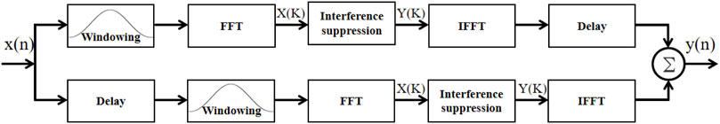
Figure 3. Flowchart of frequency-domain anti-jamming implementation.
The detailed implementation process of interference suppression in Figure 3 is illustrated in Figure 4. The interference suppression component is the core of frequency-domain anti-jamming, which is divided into FFT-based power spectral density estimation, anti-jamming threshold generation, frequency-domain weight generation, and weighting. Among these, threshold generation is the key to interference suppression. In other words, a reasonable interference detection threshold is crucial for frequency-domain anti-jamming, and whether the threshold is set appropriately largely determines the performance of the frequency-domain anti-jamming algorithm.
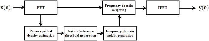
Figure 4. Interference suppression process flowchart.
In recent years, many scholars have further investigated frequency-domain adaptive filtering techniques. In 2016, the Rezaei M J team at Iran University of Science and Technology employed a frequency-domain transformation method based on multi-scale short-time Fourier transform (STFT), enhancing the signal’s aggregation in the frequency domain and improving the filter’s anti-jamming capability. However, this method came at the cost of increased computational complexity [73]. In the same year, the Chang C L team at National Pingtung University of Science and Technology in Taiwan combined compressed sensing with frequency-domain processing techniques, reducing the system sampling rate and thereby decreasing the computational complexity of anti-jamming processing. Nevertheless, the performance in suppressing wideband interference remained suboptimal [74]. In 2017, the Chien Y R team utilized wavelet packet transform (WPT), which offers higher time-frequency resolution than wavelet transform (WT), to detect interference parameters and estimate the current waveform of the interference, thereby suppressing it. This further enhanced the signal’s aggregation in the frequency domain, but the method still struggled when dealing with a large number of wideband interferences [75]. In 2024, the Ding M team at Hong Kong Polytechnic University introduced a Signal Prediction-Assisted Reference Spectrum Model (SPRSM) to mitigate the loss of desired signals during frequency-domain filtering. The introduced SPRSM equalizer leverages GNSS signal prediction to compensate for distortion, reducing signal degradation and quality loss caused by signal distortion during frequency-domain filtering [76].
In summary, frequency-domain anti-jamming techniques are only suitable for dealing with multiple narrowband interferences and broadband interferences that have certain spectral energy aggregation. When it comes to broadband interferences with poor energy distribution aggregation or a large number of broadband interferences, the interference suppression capability of frequency-domain anti-jamming techniques still falls short.
2.3.3 Transformation-domain anti-jamming
Transformation-domain anti-jamming technology involves mapping the received signal into a transformation domain (such as the frequency domain or time-frequency domain). By exploiting the differences in characteristics between the interference and the desired signal in the transformation domain, interference detection algorithms are used to estimate the parameters of the interference. The interference signal can then be removed using pulse blanking methods or filters. The processed signal is subsequently inverse-transformed back to the time domain. Alternatively, the interference signal waveform can be reconstructed based on the estimated parameters and then eliminated from the received signal [75, 77].
The choice of transform domain or transformation method can lead to differences in the obtained interference distribution characteristics. Therefore, the transform domain and method need to be selected or optimized based on the types of interference in the receiving environment. The frequency domain is the earliest and most commonly used transform domain. Stationary narrowband interference signals exhibit high aggregation in the frequency domain, and frequency-domain data can be quickly obtained through FFT, offering strong practicality [75]. With the continuous development of interference technology, non-stationary time-varying interference has become increasingly prominent in adversarial environments. As a result, cyclic spectrum analysis and time-frequency (TF) analysis methods have been introduced into the field of anti-jamming. Typical TF transformation methods include Short-Time Fourier Transform (STFT), Wavelet Transform (WT), Wigner-Ville Distribution (WVD), and Fractional Fourier Transform (FrFT), among others. To further enhance the aggregation of interference signals in the transform domain and achieve more accurate detection results, several new transformation methods have been proposed and applied in the field of GNSS interference detection and suppression. In 2015, the Sun K team at Hefei University of Technology combined reassignment techniques with the Smoothed Pseudo Wigner-Ville Distribution (SPWVD) to propose the Reassigned Smoothed Pseudo Wigner-Ville Distribution (RSPWVD). This method enhanced the aggregation of interference signals in the TF domain, improved TF resolution, and reduced cross-term interference [78]. In 2016, the Rezaei M J team at Iran University of Science and Technology employed multi-scale STFT, achieving improved TF aggregation of interference signals at the cost of a slight increase in computational complexity [73]. In the same year, the Li J team at Tianjin University of Technology used Time-Modulated Windowed All-Phase Discrete Fourier Transform (TMWAP-DFT) to detect the frequency parameters of pulse signals emitted by Distance Measurement Equipment (DME) [77]. In 2017, the Chien Y R team utilized WPT to detect the TF parameters of fast-varying interference signals and predict their waveforms [75]. Also in 2017, the Mosavi M R team at Iran University of Science and Technology demonstrated that WPT could suppress narrowband and chirp interference with a capability of up to 55 dB [79]. With the gradual maturation of compressed sensing theory, in 2016, the Chang C L team at National Pingtung University of Science and Technology in Taiwan introduced compressed sensing theory into the field of GNSS anti-jamming to reduce the sampling rate and the computational complexity of interference detection and suppression [74]. In 2024, the Sun K team at Hefei University of Technology proposed a Generalized Time-Fractional Bandwidth Product (GTFrBP) search model based on FrFT combined with a notch filter. Experimental results demonstrated that this model achieved high precision in detecting the optimal FrFT order [80].
The efficiency of transformation-domain anti-jamming techniques is independent of the number of interferences and is suitable for scenarios with multiple narrowband interferences. Moreover, these techniques can effectively handle non-stationary broadband interference signals such as linear frequency-modulated (LFM) signals. Therefore, they are considered a very promising anti-jamming strategy. However, these algorithms are only applicable to narrowband interferences and broadband interferences with strong TF energy distribution aggregation. They are powerless in the case of complex forms of broadband interferences or a large number of broadband interferences.
2.3.4 Spatial anti-jamming
Spatial filtering is one of the most effective methods for suppressing spatial interference signals. It employs adaptive null-steering antennas to achieve adaptive filtering functions. The working principle involves using adaptive weighting coefficients to control the antenna pattern, thereby filtering out interference signals in the spatial domain without degrading the gain of the desired signal [81]. The structure is shown in Figure 5.
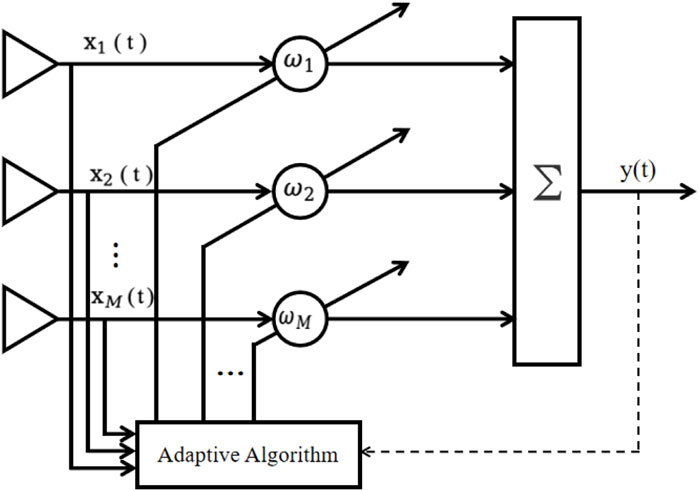
Figure 5. Spatial anti-jamming structure.
Classic spatial anti-jamming algorithms include the Power-Inversion (PI) method [82], Minimum Variance Distortionless Response (MVDR) method [83, 84], and Minimum Power Distortionless Response (MPDR) method [85]. The PI algorithm does not require prior information about the jamming and desired signals; it can form nulls in the direction of strong jamming to suppress it. This method has low computational complexity and is easy to implement. However, its suppression performance against weak jamming (JNR <20 dB) is not satisfactory [86], and it lacks constraints on the desired signal, making it unable to guarantee the gain of the desired signal. The MVDR and MPDR algorithms impose constraints on the beam response in the direction of the desired signal, enabling the spatial filter to have a distortionless response to the desired signal while suppressing jamming from other directions. However, the MVDR algorithm requires estimating the covariance of interference and noise without the desired signal, whereas the MPDR leverages the characteristic that the GNSS signal power at the navigation receiver is significantly lower than that of the jammer noise, directly using the covariance of the received signal to solve for the spatial filter weights. Since these methods were introduced into the field of GNSS receiver anti-jamming in the 1990s, they have been successfully applied in practical equipment. For example, Boeing developed a four-element antenna array anti-jamming receiver that can adaptively adjust the nulls in the antenna beam pattern, enhancing the anti-jamming capability of satellite navigation equipment on Joint Direct Attack Munitions (JDAM) [87]. Similarly, NovAtel developed a miniaturized GNSS Anti-Jam Technology (GAJT) antenna, employing a seven-element antenna array, capable of countering up to six strong jamming sources [88].
To enhance the capability of spatial filters to counter complex jamming environments, multi-antenna-based spatial anti-jamming technologies have been further researched. Regarding the selection of reference elements in the PI algorithm, in 2016, Chen F’s team from the National University of Defense Technology analyzed the impact of the relative position of reference elements on anti-jamming performance under different interference conditions [89]. In the same year, the team proposed an optimal element selection method based on joint acquisition results, adaptively selecting reference elements based on optimal acquisition outcomes [90, 91]. In 2017, Lu Z’s team from the National University of Defense Technology suggested that selecting appropriate reference elements can reduce the impact of channel mismatch and proposed choosing the optimal reference element based on output power to improve interference suppression performance [92]. Addressing the issue where blind adaptive beamforming algorithms (such as the PI algorithm) do not constrain the desired signal, leading to distortion in satellite navigation signals, in 2012, Zhang Y D’s team from Villanova University proposed a method to estimate the steering vector based on the autocorrelation characteristics of navigation signals, thereby estimating the carrier error introduced by blind adaptive beamforming and compensating for it [93]. In 2016, Daneshmand S’s team from the University of Calgary utilized the symmetry in symmetric arrays to estimate the signal distortion parameters introduced by adaptive filters, subsequently calculating compensation weight vectors [94]. In high-dynamic application scenarios, where rapid changes in interference direction over short periods lead to performance degradation in conventional algorithms, besides typical null broadening strategies [95], in 2016, Chen L W’s team from Wuhan University proposed using a Hidden Markov Process to detect interference characteristics within sub-bands, then employing a multi-constraint PI algorithm to eliminate interference, thereby enhancing the efficiency of processing rapidly changing interference [96]. In 2014, Wang W’s team from the Civil Aviation University of China proposed leveraging the sparsity of the spatial spectrum of interference signals, using short snapshot (single snapshot) Direction of Arrival (DOA) estimation methods to estimate interference directions, quickly constructing interference subspaces, and then suppressing interference through orthogonal subspace projection algorithms. This method can rapidly update spatial filter weights based on the instantaneous DOA information of interference sources, thus exhibiting high robustness in high-dynamic environments [97]. Regarding spatially proximal interference (interference incident within the main beam) causing a decrease in the output SNR of spatial filters, in 2017, Gong Y’s team from Northwestern Polytechnical University proposed a covariance matrix reconstruction method. This approach first eliminates spatially proximal interference from the covariance matrix to achieve the suppression of other interferences, and then uses an eigenvalue protection matrix to eliminate spatially proximal interference [98]. Addressing the drawback of uniform linear arrays being unable to distinguish between desired and interference signals located on the same ambiguity cone, in 2013, Wang X’s team from the University of New South Wales analyzed the relationship between spatial correlation coefficients [99] among signals and array orientation, proposing to rotate the linear array to obtain optimal anti-jamming performance by optimizing the spatial correlation coefficient [100]. In certain jamming scenarios, where high spatial correlation between interference and desired signals leads to reduced interference suppression effectiveness in fixed-array-based spatial filtering algorithms, in 2016, Wang X’s team from the University of New South Wales and Amin M G’s team from Villanova University respectively researched reconfigurable array technologies. These methods improve anti-jamming performance without increasing RF channels by selecting appropriate elements in redundant antenna arrays to reduce the correlation between interference and desired signals [101, 102].
3 Principle of LEO-SOP positioning
LEO satellites signals are generally non-navigation/non-cooperative signals, which either do not contain or make it difficult to extract navigation information. Therefore, it is challenging to obtain pseudorange measurements, and positioning is usually achieved by extracting Doppler shifts. This section introduces the principle model of LEO-SOP Doppler positioning and the working process of the receiver. The details are as follows.
3.1 LEO-SOP Doppler positioning principle model
By measuring the instantaneous Doppler frequency of LEO satellites, positioning can be achieved. The principle is based on the Doppler effect caused by the high-speed motion of satellites relative to the ground. The change in Doppler frequency reflects the relationship between the satellite’s position and the navigation terminal’s position. The relative velocity between the receiver and the satellite can be obtained using the carrier Doppler measurements of the satellite signal and its wavelength. This constrains the receiver’s position to the surface of a cone with the satellite’s position as the origin, the satellite’s velocity direction as the axis, and the opening angle determined by the relative velocity. When a sufficient number of LEO satellites are received, the receiver’s position can be determined by the intersection of multiple conical surfaces calculated from the measurements. A schematic diagram of the multi-satellites Doppler positioning principle is shown in Figure 6. When LEO satellite visibility is insufficient, multiple measurements from a single satellite can also be used. Similarly, the intersection of multiple conical surfaces calculated from these measurements can determine the receiver’s position. The basic principle is the same as that of multi-satellites Doppler positioning. A schematic diagram of the single-satellite Doppler positioning principle is shown in Figure 7.
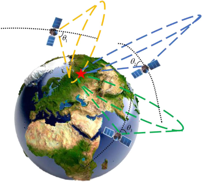
Figure 6. Schematic diagram of multi-satellites doppler positioning algorithm principle.
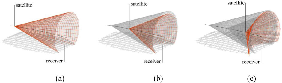
Figure 7. Schematic Diagram of Single-Satellite Doppler Positioning Principle. (a) First measurement, (b) Second measurement, (c) Third measurement.
Below, the Doppler positioning equation is derived from the pseudorange positioning equation. Taking a single satellite as an example, the traditional pseudorange positioning equation is:
In the equation,
In the equation, K represents the Kth satellite received,
Taking the derivative of both sides of Equation 1 yields:
In the Equation 3,
Where,
The second term
By combining Equations 4, 5, we obtain:
The above equation is the Doppler positioning equation, which establishes a linear relationship between seven states (receiver position, velocity, and frequency bias) and the instantaneous Doppler shift. If the receiver is stationary, the number of unknowns in the equation reduces to four, namely,
Before solving the navigation Equation 7, the expression for the three-dimensional vector
Where,
Therefore, Equation 8 can be written as:
From Equation 10, the physical meaning of the three-dimensional vector expression
3.2 LEO-SOP receiver operation process
Since LEO satellites are generally not designed for navigation purposes, it is difficult to obtain traditional navigation observation information such as pseudoranges. Therefore, LEO-SOP receivers typically need to analyze the characteristics of LEO satellite signals, such as signal structure and signal power, to extract navigation observation information. Additionally, they rely on external ephemeris data to assist in obtaining satellite position and velocity parameters. These steps are essential for the receiver to complete its own positioning and obtain PNT status. By substituting TLE parameters into the SGP4 model, the satellite’s position and velocity at a specific moment can be calculated.
Generally, after the antenna of a LEO-SOP receiver completes the acquisition of the SOP signal, it uses a down-conversion device to shift the frequency of the collected signal to an intermediate frequency. Subsequently, the SOP signal is detected, and navigation observation information is analyzed and extracted. Finally, the receiver estimates its own PNT status using the observation information and external ephemeris data. The operation process of the LEO-SOP receiver is shown in Figure 8.
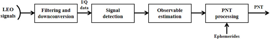
Figure 8. Flowchart of LEO-SOP receiver operation.
4 Analysis of the system-level anti-jamming capability of LEO-SOP
This section analyzes the system-level anti-jamming capability of the LEO-SOP. It first provides a detailed introduction to the constellation characteristics of the Iridium, Orbcomm, and Starlink satellites within the LEO system. The analysis of system-level anti-jamming capabilities is then conducted from several aspects, including GDOP (Geometric Dilution of Precision) values, satellite visibility, SNR at the receiver, and downlink user frequencies. Without loss of generality, the GPS system from the GNSS is selected as a representative for comparative analysis with the LEO system.
4.1 Characteristics of LEO constellations
This subsection selects the relatively mature Iridium and Obrcomm satellites, as well as the rapidly developing Starlink satellites, as representatives of the LEO system. It provides a detailed introduction to the constellation characteristics of each representative satellite, laying the theoretical foundation and technical support for subsequent analysis of anti-jamming capabilities. The details are as follows.
4.1.1 Iridium system
The Iridium system is a global satellite mobile communication network developed by Motorola and others, consisting of 66 LEO satellites. In January 2017, the first batch of 10 Iridium NEXT satellites was successfully launched. On 20 May 2023, an additional five backup satellites were launched aboard SpaceX’s Falcon 9 rocket [103–105]. Currently, the Iridium NEXT constellation has 80 satellites in orbit (66 of which are actively transmitting signals, with the remaining 14 serving as backups). A schematic diagram of the Iridium NEXT system constellation is shown in Figure 9a.
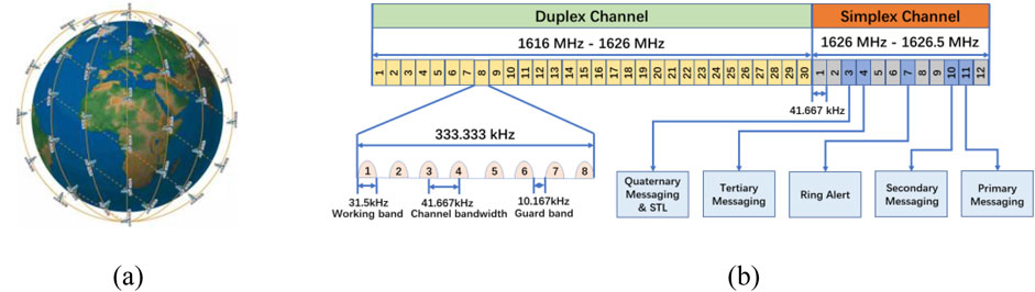
Figure 9. Basic satellite orbit distribution and signal system of the iridium system. (a) Constellation orbit, (b) L-band frequency allocation.
The Iridium system’s satellites have an orbital inclination of 86.4° and an orbital period of 100.13 min, enabling global coverage. The user link employs a combination of FDMA/TDMA/SDMA/TDD multiple access techniques. The 48 spot beams of each satellite are grouped into sets of 12 adjacent beams, which spatially reuse the total available frequency band (SDMA). Within each beam, the frequency band is further divided into multiple TDMA channels using FDMA. For the same user, the uplink and downlink within each TDMA channel are time-division multiplexed (TDD), meaning the uplink and downlink occupy different time slots within the same frame of the same TDMA carrier [106–110].
The total bandwidth allocated to Iridium is 1,616.0 MHz–1,626.5 MHz. Specifically, 1,616.0 MHz - 1,626.0 MHz is used for full-duplex channels as the service channels, while 1,626.0 MHz - 1,626.5 MHz is designated for the downlink simplex channel, used as the signaling channel. The 0.5 MHz bandwidth of the downlink channel is divided into 12 channels, each with a bandwidth of 41.67 kHz. The FDMA frequency allocation for the user links of the Iridium system is shown in Figure 9b; [111–114].
4.1.2 Orbcomm system
Orbcomm satellites are a joint project between Orbital Sciences Corporation of the United States and Teleglobe of Canada. This satellite system offers several advantages, including low investment, short development cycles, dual capabilities in communication and positioning, lightweight satellites, mobile phone user terminals, high levels of system automation, and strong autonomous functionality. Utilizing the Orbcomm system, users can engage in applications such as remote data collection, system monitoring, tracking of vehicles, vessels, and mobile facilities, as well as sending and receiving emails. In 2008, Orbcomm announced the deployment of its second-generation satellite (OG2) constellation. Currently, there are 12 OG2 satellites in orbit, evenly distributed across four primary orbital planes. The OG2 satellites operate at an altitude of 620 km with an orbital inclination of 47° and an orbital period of 97 min. A schematic diagram of the Orbcomm constellation is shown in Figure 10a; [115–118].
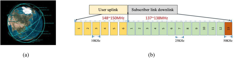
Figure 10. Orbcomm Satellite orbital distribution and signal System. (a) Constellation orbit, (b) downlink allocation.
The downlink of Orbcomm satellites occupies the frequency band of 137–138 MHz, which includes 13 channels. Twelve channels, each with a bandwidth of 25 kHz, are used for communication with user terminals (employing FDMA multiple access), while the remaining channel, with a bandwidth of 50 kHz, is used for communication with gateway stations. All Orbcomm satellites share the 12 user downlink channels. The user downlink employs SDPSK modulation. The downlink allocation of the Orbcomm constellation is illustrated in Figure 10b; [119, 120].
4.1.3 Starlink system
Starlink is a Non-Geostationary Orbit (NGSO) satellite system being developed by SpaceX, an American space services company. It boasts numerous advantages, including extensive coverage, high signal strength, and a large number of satellites. The system consists of two sub-constellations: a LEO constellation at an altitude of 550 km and a Very Low Earth Orbit (VLEO) constellation at an altitude of 340 km. Although the Starlink constellation is not yet fully deployed, the number of satellites already in orbit far surpasses that of other LEO constellations. By November 2024, the number of Starlink satellites in orbit had exceeded 6,000, significantly more than any other existing LEO constellation. The system is projected to grow into a mega-constellation of nearly 12,000 satellites to provide satellite internet services. Figure 11 illustrates the schematic diagram of the deployed constellation [121–123].
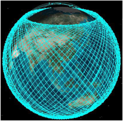
Figure 11. Schematic diagram of starlink constellation deployment.
The constellation design of Starlink has gone through two phases. As early as April 2020, SpaceX adjusted the orbital altitudes of all satellites in the LEO constellation from 1,150 km to 550 km to a range of 540–570 km in the first phase configuration. The modified configuration of the first phase of the Starlink constellation is shown in Table 3; [124, 125].
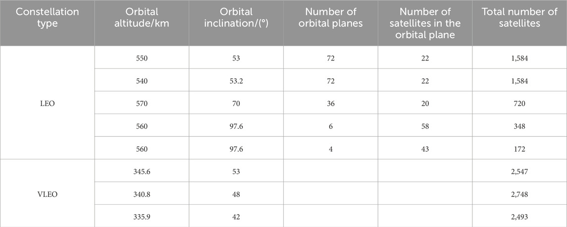
Table 3. Configuration of the first phase of the starlink constellation.
In May 2020, SpaceX submitted the constellation design for its second-generation Starlink system (Gen2), which includes 30,000 satellites.
The Starlink system features inter-satellite communication capabilities. Network users will utilize the V and Ku bands, while the V and Ka bands will primarily be used for connecting gateways and for tracking, telemetry, and control. The LEO sub-constellation satellites will operate in the Ku, Ka, and V bands, with the Ku band used for downlink operations. The VLEO sub-constellation satellites will only use the V band. The frequency bands used by the Starlink system are shown in Table 4.
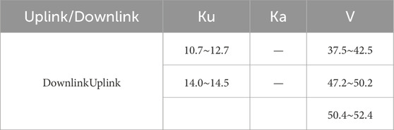
Table 4. Frequency bands of the starlink system.
4.2 Analysis of the system-level anti-jamming capability
LEO-SOP demonstrates a significant improvement in the system-level anti-jamming capability due to the numerous inherent advantages of LEO constellations compared to traditional GNSS navigation constellations. The following analysis will focus on GDOP values, satellite visibility, SNR at the receiver, and downlink user frequency. During the analysis, four currently well-established LEO-SOP positioning scenarios will be considered: Iridium single-constellation positioning, Orbcomm single-constellation positioning, Starlink single-constellation positioning, Iridium/Orbcomm dual constellation joint positioning, as well as a comparative scenario with GPS positioning.
4.2.1 GDOP value
Using STK software, the GDOP values of various constellations under five scenarios in the Asia-Pacific region over a 24-h period were simulated. The horizontal axis represents the latitude values, while the vertical axis represents the corresponding GDOP values. The results are shown in Figure 12.
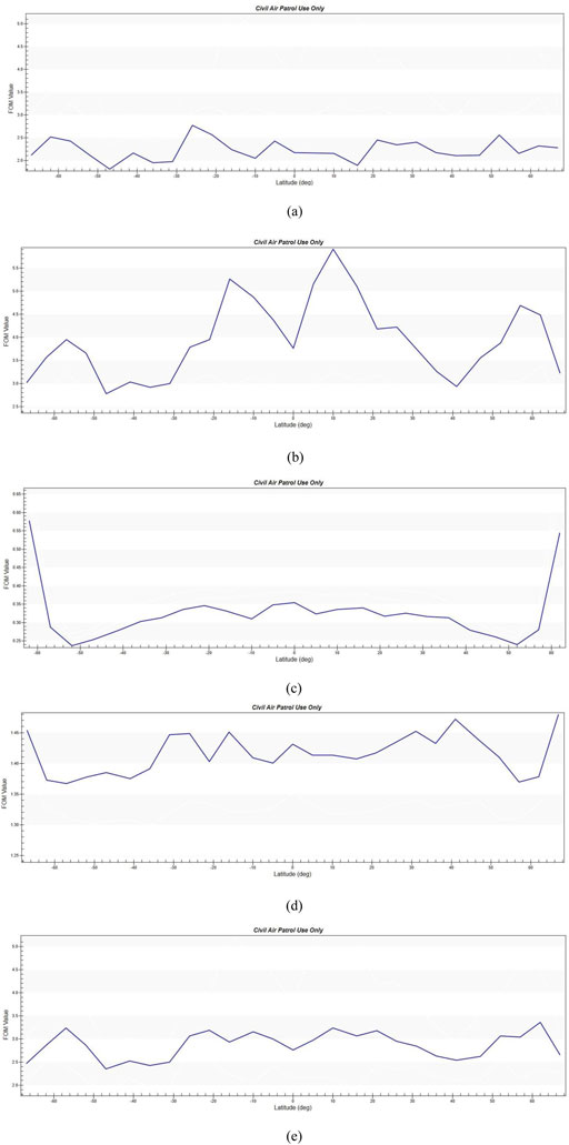
Figure 12. Gdop values of various constellations. (a) Iridium single constellation, (b) orbcomm single constellation, (c) Starlink single constellation, (d) Iridium/orbcomm dual constellation, (e) GPS satellites.
As can be seen from Figure 12, the GDOP value of the Orbcomm single-constellation performs relatively the worst. This is because Orbcomm is a Walker constellation with only 12 available satellites. In contrast, the GDOP value of the Iridium single constellation is better than that of GPS satellites. Although Iridium has a polar orbit type, its constellation consists of 66 satellites, which is a relatively large number, resulting in better GDOP performance. Moreover, when combined with Orbcomm to form a dual constellation, the GDOP value improves significantly, effectively enhancing the satellite geometry. The Starlink constellation, with the largest number of satellites, exhibits the best GDOP performance.
4.2.2 Satellite visibility
Similarly, using STK software to simulate the satellite visibility of each constellation in the five scenarios in Beijing area over a 24-h period, the results are shown in Figure 13.
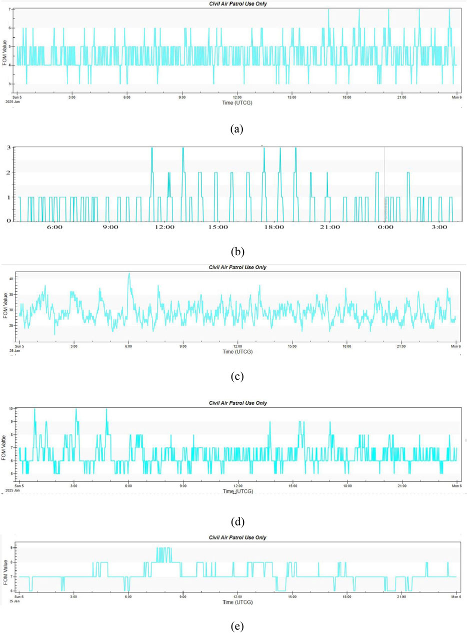
Figure 13. Satellite visibility of various constellations. (a) Iridium single constellation, (b) orbcomm single constellation, (c) Starlink single constellation, (d) Iridium/orbcomm dual constellation, (e) GPS satellites.
It can be observed that the satellite visibility of each constellation follows a similar trend to their GDOP performance. The Starlink constellation boasts the best visibility. Although the Iridium constellation has a relatively large number of satellites, its orbital configuration is suboptimal, while the Orbcomm constellation suffers from a limited number of available satellites. However, in the case of dual-constellation combinations, the satellite geometry can be effectively improved.
4.2.3 Received signal power
The GPS constellation employs satellites in Medium-Earth-Orbit (MEO). The high orbital altitude results in significant signal attenuation during the transmission of navigation signals, leading to low received power (typically between −160 dBW and −155 dBW). The signals are often submerged in noise, resulting in a low SNR, generally ranging from −20 dB to −30 dB.In contrast, LEO satellites, with their lower orbital altitudes (typically between 700 km and 900 km), experience less signal attenuation during propagation. This results in a higher received SNR (commonly between 15 dB and 30 dB). In terms of received signal power, LEO satellite signals have a significant advantage over GPS signals in terms of anti-jamming capability.
4.2.4 Downlink user frequency
Compared with the user downlink spectrum of GNSS applications, which are mostly concentrated in the L-band, LEO satellites have a wide range of available frequency bands due to the numerous applications from various LEO systems. These bands (100 MHz - 42.5 GHz) provide extensive coverage and greater flexibility in terms of anti-jamming capabilities. Unlike current GNSS systems, most LEO satellites operate at very high frequencies, which also enhances their resilience to interference. Detailed parameters of the downlink frequencies and bandwidths of major domestic and international LEO satellites, refer to Table 1. Figure 14 illustrates the downlink spectrum of GNSS navigation systems and selected LEO systems, including Orbcomm, Tianqi, StarNet, Iridium, Globalstar, Starlink, and OneWeb constellations.
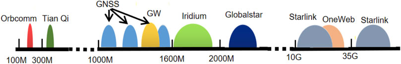
Figure 14. Spectrum range illustration of LEO satellites and GNSS satellites.
In summary, LEO-SOP systems have significant advantages over GNSS systems in terms of received signal power and downlink user frequencies, which contribute to better anti-jamming capability. Regarding GDOP values and satellite visibility, LEO-SOP systems also show clear advantages over GNSS, except for some constellations with fewer satellites and less favorable orbital configurations. Moreover, adopting a dual-constellation system can greatly mitigate potential deficiencies in satellite numbers and orbital configurations that may exist in a single constellation.
5 Future challenges
Although LEO-SOP systems have significant advantages over GNSS systems in terms of anti-jamming capability, in everyday positioning scenarios, they are still often affected by various adverse electromagnetic environments, such as urban multipath interference and malicious human-made interference. Therefore, researching anti-jamming algorithms specifically for LEO-SOP positioning holds extremely high application value. In addition, there are still several anti-jamming-related challenges that deserve attention.
5.1 Anti-broadband interference under single-antenna reception and mitigation of desired signal loss
Due to the relatively narrow downlink signal bandwidth of LEO satellites (e.g., the Iridium system has a bandwidth of 500 kHz, while the Orbcomm system has only 25 kHz), and the fact that single-antenna receivers remain the preferred choice for most LEO satellite receptions, the available anti-jamming measures are limited when facing wideband or severe interference environments. Moreover, the signal quality degradation caused by anti-jamming measures is more severe given the already narrow signal bandwidth. To address this challenge, future research on single-antenna anti-jamming will focus on how to counteract the effects of wideband interference and mitigate the loss of desired signals during the anti-jamming process, thereby reducing signal distortion and quality degradation caused by signal distortion.
5.2 Measurement estimation in low SNR environments
Currently, the majority of research on LEO-SOP positioning is based on the calculation and estimation of observations under relatively high SNR conditions. However, in most usage scenarios, various factors can lead to a lower SNR of the received LEO-SOP signals. For example, low-cost or small-sized antennas inherently cannot provide high antenna gain; rain fade or other path losses particularly affect the energy of high-frequency band signals, resulting in a lower SNR of the received signals; and harsh interference environments can further reduce the signal SNR. A low SNR makes signal detection more challenging and decreases the accuracy of observation estimation. Therefore, future research needs to further explore how to achieve precise estimation of observations in low SNR environments.
5.3 Interference scenarios from other satellites
With the construction and deployment of mega-constellations represented by Starlink, interference among different satellites within the same system will become increasingly common. Under such conditions, the receiving environment will be more challenging, as the receiving end often faces signals from other satellites that have similar frequencies and power levels. Therefore, future research needs to further explore how to accurately receive and estimate the target signals in scenarios with interference from other satellites.
6 Conclusion
This paper provides a comprehensive review of LEO-SOP and anti-jamming technology research, and analyzes the anti-jamming capability of the LEO-SOP system. Firstly, the current research status of LEO-SOP and anti-jamming technologies is summarized, including the Doppler positioning principle model of LEO-SOP and the workflow of the receiver. Secondly, the anti-jamming capabilities of the LEO-SOP system are analyzed. Finally, the challenges and future development directions of LEO-SOP anti-jamming technologies are discussed, aiming to provide a solid technical foundation for the secure application of LEO-SOP.
Author contributions
LY: Software, Writing – original draft, Writing – review and editing. BF: Investigation, Resources, Supervision, Formal analysis, Funding Acquisition, Writing – review and editing. HQ: Conceptualization, Methodology, Writing – original draft, Writing – review and editing. DX: Writing – review and editing. MW: Writing – review and editing. BG: Investigation, Resources, Supervision, Writing – review and editing. SC: Investigation, Supervision, Writing – review and editing. CW: Data curation, Formal Analysis, Supervision, Writing – review and editing. XW: Project administration, Resources, Supervision, Writing – review and editing. JS: Investigation, Resources, Supervision, Writing – review and editing. DJ: Investigation, Resources, Supervision, Writing – review and editing. HW: Investigation, Resources, Supervision, Writing – review and editing. HY: Investigation, Resources, Supervision, Writing – review and editing. BL: Investigation, Resources, Supervision, Writing – review and editing. SS: Investigation, Resources, Supervision, Writing – review and editing.
Funding
The author(s) declare that financial support was received for the research and/or publication of this article. This research was funded from the Army Academy of Artillery and Air Defense under Grant 220214003.
Acknowledgments
The authors would like to thank the editors and reviewers for their efforts to help the publication of this paper.
Conflict of interest
Author SS was employed by Shaanxi Datang Gas Safety Technology Co., LTD.
The remaining authors declare that the research was conducted in the absence of any commercial or financial relationships that could be construed as a potential conflict of interest.
The reviewer KW declared a shared affiliation with the author BF to the handling editor at time of review.
Generative AI statement
The author(s) declare that no Generative AI was used in the creation of this manuscript.
Publisher’s note
All claims expressed in this article are solely those of the authors and do not necessarily represent those of their affiliated organizations, or those of the publisher, the editors and the reviewers. Any product that may be evaluated in this article, or claim that may be made by its manufacturer, is not guaranteed or endorsed by the publisher.
References
1. Jia Q, Zukun L, Baojun L, Jie S, Zhibin X, Zhi W, et al. A survey of GNSS interference monitoring technologies. Front Phys (2023) 11. doi:10.3389/fphy.2023.1133316
2. Danning Z, Yu L. Effects of ionosphere dispersion on wideband GNSS signals. Front Phys (2023) 11. doi:10.3389/fphy.2023.1103159
3. Shaojie N, Binbin R, Feiqiang C, Zukun L, Jie W, Pengcheng M, et al. GNSS spoofing suppression based on multi-satellite and multi-channel array processing. Front Phys (2022) 10. doi:10.3389/fphy.2022.905918
4. Takeshi I, Motoyuki K, Yusaku O, Tatsuya F, Fumiaki T, Iwao U. GNSS-acoustic observations of seafloor crustal deformation using a wave glider. Front Earth Sci 11 March 2021 Sec Solid Earth Geophys (2021) 9. doi:10.3389/feart.2021.600946
5. Ting Y, Nan C. A preliminary view of the CYGNSS soil moisture-vegetation activity linkage. Front. For. Glob. Change, 30 November 2023. Sec For Management (2023) 6. doi:10.3389/ffgc.2023.1320432
6. Haopeng W, Guorui X, Peiyuan Z, Peigong L, Zhengyang X, Baoxiang Z. Combining Galileo HAS and beidou PPP-B2b with Helmert coordinate transformation method. GPS Solutions (2025) 29:35. doi:10.1007/s10291-024-01789-2
7. Peiyuan Z, Guorui X, Lan D. Initial performance assessment of Galileo high accuracy service with software-defined receiver. GPS Solutions (2024) 28:2. doi:10.1007/s10291-023-01540-3
8. Xiangjun L, Zukun L, Muzi Y, Wenxiang L, Feixue W, Yi Y, et al. Tradeoff of code estimation error rate and terminal gain in SCER Attack. Ieee Trans instrumentation Meas (2024) 73:1–12. doi:10.1109/tim.2024.3406807
9. Alexander M, Laurie B, Robert C, Walterio M, Jianing C, Colin G, et al. Visual odometry using pixel processor arrays for unmanned aerial systems in GPS denied environments. Front Robot Ai, 29 September 2020 Sec Robot Vis Artif Perception (2020) 7:126. doi:10.3389/frobt.2020.00126
10. Matteo F, Riccardo B, Matteo M. On the precision of 6 DoF IMU-LiDAR based localization in GNSS-denied scenarios. Front Robot Ai, 24 January 2023 Sec Field Robotics (2023) 10:1064930. doi:10.3389/frobt.2023.1064930
11. Hu Z, Zhang L, Ji Y. Applications of differential barometric altimeter in ground cellular communication positioning network. IET Sci Meas &Technology (2020) 14(3):322–31. doi:10.1049/iet-smt.2018.5316
12. Sial M, Deng Y, Ahmed J, Nallanathan A, Dohler M. Modeling and analysis of cellular V2X communications over shared channels. IEEE Trans Vehicular Technology (2019) 68(12):12079–92. doi:10.1109/TVT.2019.2945481
13. Zhang J, Li Y, Su T, He X. Quadratic FM signal detection and parameter estimation using coherently integrated trilinear autocorrelation function. IEEE Trans Signal Process (2020) 68:621–33. doi:10.1109/tsp.2020.2965279
14. Shtark T, Gurfil P. Regional positioning using a low Earth orbit satellite constellation. Celestial Mech Dynamical Astron (2018) 130(2):14–28. doi:10.1007/s10569-017-9811-7
15. Reid TG, Neish AM, Walter TF, Enge PK. Leveraging commercial broadband leo constellations for navigating. In: Proceedings of the 29th International Technical Meeting of the Satellite Division of the Institute of Navigation (Ion Gnss+ 2016), (2016) 12. Portland, Oregon. 2016: 2016–6.09. doi:10.33012/2016.14729
16. Han Y, Wang L, Fu W, Zhou H, Li T, Xu B, et al. LEO navigation augmentation constellation design with the multiobjective optimization approaches. Chin J Aeronaut (2021) 34(4):265–78. doi:10.1016/j.cja.2020.09.005
17. Zhang Y, Liu A, Li P, Jiang S. Deep learning (DL)-Based channel prediction and hybrid beamforming for LEO satellite massive MIMO system. IEEE Internet Things J (2022) 9(23):23705–15. doi:10.1109/jiot.2022.3190412
18. Kodheli O, Maturo N, Chatzinotas S, Andrenacci S, Zimmer F. NB-IoT via LEO satellites: an efficient resource allocation strategy for uplink data transmission. IEEE Internet Things J (2022) 9(7):5094–107. doi:10.1109/jiot.2021.3109456
19. Gasparollo L, Bailey E. The globalstar system: a complement to terrestrial mobile networks. Eur Workshop Mobile and Personal Satellite Commun (1996) 10–5. doi:10.1109/EMPS.1996.864081
20. Di B, Song L, Li Y, Poor HV. Ultra-dense LEO: integration of satellite access networks into 5G and beyond. IEEE Wireless Commun (2019) 26(2):62–9. doi:10.1109/mwc.2019.1800301
21. Yao L, Qin H, Gu B, Shi G, Sha H, Wang M, et al. A study on anti-jamming algorithms in low-earth-orbit satellite signal-of-opportunity positioning systems for unmanned aerial vehicles. Drones (2024) 8(4):164. doi:10.3390/drones8040164
22. Levanon N. Quick position determination using 1 or 2 LEO satellites. IEEE Trans Aerospace Electron Syst (1998) 34(3):736–54. doi:10.1109/7.705883
23. Levanon N. Instant active positioning with one LEO satellite. Navigation (1999) 46(2):87–95. doi:10.1002/j.2161-4296.1999.tb02397.x
24. Fisher KA. The navigation potential of signals of opportunity-based time difference of arrival measurements. USA: Air Force Institute of Technology (2005).
25. Tan Z, Qin H, Cong L, Zhao C. New method for positioning using IRIDIUM satellite signals of opportunity. IEEE access (2019) 7:83412–23. doi:10.1109/access.2019.2924470
26. Tan Z, Qin H, Cong L, Zhao C. Positioning using IRIDIUM satellite signals of opportunity in weak signal environment. Electronics (2019) 9(1):37. doi:10.3390/electronics9010037
27. Wang D, Qin H, Huang Z. Doppler positioning of LEO satellites based on orbit error compensation and weighting. IEEE Trans Instrumentation Meas (2023) 72(1):1–11. doi:10.1109/tim.2023.3286001
28. Zhang Y, Qin H, Shi G. Doppler positioning based on globalstar signals of opportunity. In: 2023 5th International Conference on Electronic Engineering and Informatics (EEI). IEEE (2023). p. 666–9.
29. Qin H, Zhang Y, Yang Y, Lv H. Fast clustering satellite selection based on Doppler positioning GDOP lower bound for LEO constellation. IEEE Trans Aerospace Electron Syst (2024) 60(6):9401–10. doi:10.1109/taes.2024.3443021
30. Khalife J, Kassas ZM. Receiver design for Doppler positioning with LEO satellites. In: ICASSP 2019-2019 IEEE International Conference on Acoustics, Speech and Signal Processing (ICASSP). IEEE (2019). p. 5506–10.
31. Neinavaie M, Khalife J, Kassas ZM. Acquisition, Doppler tracking, and positioning with Starlink LEO satellites: first results. IEEE Trans Aerospace Electron Syst (2021) 58(3):2606–10. doi:10.1109/taes.2021.3127488
32. Neinavaie M, Kassas ZM. Unveiling Starlink LEO satellite OFDM-like signal structure enabling precise positioning. IEEE Trans Aerospace Electron Syst (2023) 60:2486–9. doi:10.1109/taes.2023.3265951
33. Farhangian F, Landry JR. Multi-constellation software-defined receiver for Doppler positioning with LEO satellites. Sensors (2020) 20(20):5866. doi:10.3390/s20205866
34. Orabi M, Khalife J, Kassas ZM. Opportunistic navigation with Doppler measurements from Iridium next and Orbcomm LEO satellites. In: 2021 IEEE Aerospace Conference (50100). IEEE (2021). p. 1–9.
35. Kozhaya S, Kanj H, Kassas ZM. Blind Doppler tracking and positioning with NOAA LEO satellite signals. In: Proceedings of the 36th International Technical Meeting of the Satellite Division of The Institute of Navigation (ION GNSS+ 2023) (2023). p. 363–72.
36. Kozhaya S, Kanj H, Kassas ZM. Multi-constellation blind beacon estimation, Doppler tracking, and opportunistic positioning with OneWeb, Starlink, Iridium NEXT, and Orbcomm LEO satellites[C]//2023 IEEE/ION Position. In: Location and Navigation Symposium (PLANS). IEEE (2023). p. 1184–95.
37. Zhao C, Qin H, Li Z. Doppler measurements from multiconstellations in opportunistic navigation. IEEE Trans Instrumentation Meas (2022) 71:1–9. doi:10.1109/tim.2022.3147315
38. Khalife J, Kassas ZM. Assessment of differential carrier phase measurements from Orbcomm LEO satellite signals for opportunistic navigation. In: Proceedings of the 32nd International Technical Meeting of the Satellite Division of The Institute of Navigation (ION GNSS+ 2019). Miami, Florida: ION (2019). p. 4053–63. doi:10.33012/2019.17031
39. Khalife J, Neinavaie M, Kassas ZM. Navigation with differential carrier phase measurements from megaconstellation LEO satellites[C]//2020 IEEE/ION Position. Location Navigation Symp (Plans) IEEE (2020) 1393–404. doi:10.1109/PLANS46316.2020.9110199
40. Khalife J, Kassas ZZM. Performance-driven design of carrier phase differential navigation frameworks with megaconstellation LEO satellites. IEEE Trans Aerospace Electron Syst (2023) 59(3):2947–66. doi:10.1109/taes.2023.3234521
41. Neinavaie M, Shadram Z, Kozhaya S, Zaher MK. First results of differential Doppler positioning with unknown Starlink satellite signals. In: 2022 IEEE Aerospace Conference (AERO). IEEE (2022). p. 1–14.
42. Zhao C, Qin H, Wu N, Wang D. Analysis of baseline impact on differential Doppler positioning and performance improvement method for LEO opportunistic navigation. IEEE Trans Instrumentation Meas (2023) 72:1–10. doi:10.1109/tim.2023.3235456
43. Wu N, Qin H, Zhao C. Long-baseline differential Doppler positioning using space-based SOP based on BPVGMM. IEEE Trans Instrumentation Meas (2023) 72:1–10. doi:10.1109/tim.2023.3276510
44. Qin H, Wu N, Zhao C. Differential positioning with Doppler measurements from Iridium satellite signals of opportunity based on linesof sight correction. J Beijing Univ Aeronaut Astronaut (2022) 50(03):748–756. doi:10.13700/j.bh.1001-5965.2022.0378
45. Morales J, Khalife J, Kassas ZM. Simultaneous tracking of Orbcomm LEO satellites and inertial navigation system aiding using Doppler measurements. In: 2019 IEEE 89th Vehicular Technology Conference (VTC2019-Spring). IEEE (2019). p. 1–6. doi:10.1109/VTCSpring.2019.8746485
46. Benzerrouk H, Nguyen Q, Xiaoxing F, Amrhar A, Nebylov AV, Landry R. Alternative PNT based on Iridium Next LEO satellites Doppler/INS integrated navigation system. In: 2019 26th Saint Petersburg international conference on integrated navigation systems (ICINS). IEEE (2019). p. 1–10.
47. Farhangian F, Landry RJ. High-order pseudorange rate measurement model for multi-constellation LEO/INS integration: case of Iridium-NEXT, Orbcomm, and Globalstar. Proc Inst Mech Eng G: J Aerospace Eng (2023) 237(4):925–39. doi:10.1177/09544100221113123
48. Du Y, Qin H, Zhao C. LEO satellites/INS integrated positioning framework considering orbit errors based on FKF. IEEE Trans Instrumentation Meas (2024) 73:1–14. doi:10.1109/tim.2024.3369693
49. Cheng J, Ren P, Deng T. A novel ranging and IMU-based method for relative positioning of two-MAV formation in GNSS-denied environments. Sensors (2023) 23(9):4366. doi:10.3390/s23094366
50. Dong P, Cheng J, Liu L. A novel anti-jamming technique for INS/GNSS integration based on black box variational inference. Appl Sci (2021) 11(8):3664. doi:10.3390/app11083664
51. Shao Y, Ma H, Zhou S, Wang X, Antoniou M, Liu H. Target localization based on bistatic T/R pair selection in GNSS-based multistatic radar system. Remote Sens (2021) 13(4):707. doi:10.3390/rs13040707
52. Łukasz L, Aleksandra R, Andrzej P, Dobryakova L, Ochin E. GNSS and LNSS positioning of unmanned transport systems: the brief classification of terrorist attacks on USVs and UUVs. Electronics (2021) 10(4):401. doi:10.3390/electronics10040401
53. Wang H, Chang Q, Xu Y. An anti-jamming null-steering control technique based on double projection in dynamic scenes for GNSS receivers. Sensors (2019) 19(7):1661. doi:10.3390/s19071661
54. Jiang Y, Fu J, Li B, Jiang P. Distributed sensitivity and critical interference power analysis of multi-degree-of-freedom navigation interference for global navigation satellite system array antennas. Sensors (2024) 24(2):650. doi:10.3390/s24020650
55. Sun Y, Chen F, Lu Z, Wang F. Anti-jamming method and implementation for GNSS receiver based on array antenna rotation. Remote Sens (2022) 14(19):4774. doi:10.3390/rs14194774
56. Lu Z, Chen F, Xie Y, Sun Y, Cai H. High precision pseudo-range measurement in GNSS anti-jamming antenna array processing. Electronics (2020) 9(3):412. doi:10.3390/electronics9030412
57. Zhang J, Cui X, Xu H, Lu M. A two-stage interference suppression scheme based on antenna array for GNSS jamming and spoofing. Sensors (2019) 19(18):3870. doi:10.3390/s19183870
58. Xu H, Cui X, Lu M. An SDR-based real-time testbed for GNSS adaptive array anti-jamming algorithms accelerated by GPU. Sensors (2016) 16(3):356. doi:10.3390/s16030356
59. Zhou C, Wang Y, Qiao C, Dai W. Anti-jamming method using complex ANF for GNSS receivers. J Natl Univ defense Technol (2016) 38(No.5).
60. Grabowski J, Hegarty C. Characterization of L5 receiver performance using DigitalPulse blanking. In: Proceedings of International Technical Meeting of the SatelliteDivision of the Institute of Navigation (ION GPS 2002) Portland, OR (2002). 1630–1635.
61. Song J, Lu Z, Liu Z. Review on the time-domain interference suppression of navigation receiver. Syst Eng Electronics (2023) 45(No.4).
62. Lv M. Research and implementation of anti-jamming technology for satellite navigation receiver based on array antenna. Harbin Engineering University (2019).
63. Chien YR. Design of GPS anti-jamming systems using adaptive notch filters. IEEE Syst J (2015) 9(2):451–460. doi:10.1109/jsyst.2013.2283753
64. Lv Q, Qin H. General method to mitigate the continuous wave interference andnarrowband interference for GNSS receivers. IET radar, sonar and navigation (2020) 14(9):1430–5. doi:10.1049/iet-rsn.2020.0115
65. Mosavi MR, Shafiee F. Narrowband interference suppression for GPS navigationusing neural networks. GPS Solutions (2016) 20(3):341–51. doi:10.1007/s10291-015-0442-8
66. Qi L. In: Research on Anti-jamming Methods for GNSS Signal Acquisition under Complex Interference Environment. Harbin Engineering University (2018).
67. DiPietro RC. An FFT based technique for suppressing narrow-band interferencein PN spreading spectrum communications systems. In: Proceedings of IEEEICASSP (1989). p. 1360–1363. doi:10.1109/ICASSP.1989.266690
68. Davidovici S, Kanterakis EG. Narrow-band interference rejection rejection usingreal-time Fourier transforms. IEEE Trans Commun (1989) 37(7):713–72.
69. Young JA, Lehnert JS. Analysis of DFT-based frequency excision algorithms fordirect-sequence spread-spectrum communications. IEEE Trans On Commun (1998) 46(8):1076–1087. doi:10.1109/26.705409
70. Li C, Hu G. A new lapped transform domain narrow-band interference excision technique. Acta Elec Sinca (2000) 28(1):117–119.
71. Sun Z. Adaptive algorithms of suppression narrow-band interference in DSSS. Harbin Engineering University (2005).
72. Zeng X, Li Z, Wang F. Study on windowing degradation of frequency-domain narrowband interference suppression algorithms in spread spectrum system. J Electronics and Inf Technology (2004) 26(8):1276–81.
73. Rezaei MJ, Abedi M, Mosavi MR. New GPS anti-jamming system based on multipleshort-time Fourier transform. IET Radar Sonar and Navigation (2016) 10(4):807–15. doi:10.1049/iet-rsn.2015.0417
74. Chang CL. Modified compressive sensing approach for GNSS signal reception in thepresence of interference. GPS Solutions (2016) 20:201–213. doi:10.1007/s10291-014-0429-x
75. Chien YR, Chen PY, Fang SH. Novel anti-jamming algorithm for GNSS ReceiversUsing wavelet-packet-transform-based adaptive predictors. IEICE Transactionson Fundamentals Electronics Commun and Computer Sci (2017) E100.A(2):602–10. doi:10.1587/transfun.e100.a.602
76. Ding M, Mi X, Chen W, Weng D, Ding W. Equalization of frequency domain adaptive filter(FDAF) using signal prediction aided ReferenceSpectrum model (SPRSM). IEEE Trans instrumentation Meas (2024) 73:1–16. doi:10.1109/tim.2024.3366269
77. Li J, Wu R, Hao Y, Wang X, Wang Y, Zhao A. DME interference suppression algorithm based on signal separation estimation theory for civil aviation system. Eurasip J WirelessCommunications and Networking (2016) (1):247. doi:10.1186/s13638-016-0736-8
78. Sun K, Jin T, Yang D. An improved time-frequency analysis method in InterferenceDetection for GNSS receivers. Sensors (2015) 15(4):9404–26. doi:10.3390/s150409404
79. Mosavi MR, Rezaei MJ, Pashaian M, Moghaddasi MS. A fast and accurate anti-jamming SystemBased on wavelet packet transform for GPS receivers. GPS Solutions (2017) 21(2):1–12.
80. Sun K, Yu B, Xu L, Elhajj M, Yotto Ochieng W. A novel GNSS anti-interference method usingFractional fourier transform and notch filtering. IEEE Trans instrumentation Meas (2024) 73:1–17. doi:10.1109/tim.2024.3451600
81. Wan Y, Chen F, Nie J, Sun G. Optimum reference element selection for GNSSPower-inversion adaptive arrays. Electronics Lett (2016) 52(20):1723–1725.
82. Moelker DJ, Pol EVD, Bar-Ness Y. Adaptive antenna arrays for interferencecancellation in GPS and GLONASS receivers[C]//Position Location and Navigation Symposium. IEEE (1996). p. 191–198. doi:10.1109/PLANS.1996.509077
83. VanTrees HL. Optimum array processing: Part IV of Detection, estimation andmodulation theory. Wiley-Interscience (2002).
84. Capon J. High-resolution frequency-wavenumber spectrum analysis. Proc of the IEEE (2005) 57(8):1408–1418. doi:10.1109/proc.1969.7278
85. Zoltowski MD, Gecan AS. Advanced adaptive null steering concepts for GPS Military Communications Conference. In: MILCOM '95 Conference Record, 3. San Diego, CA: IEEE (1995). p. 1214–1218. doi:10.1109/MILCOM.1995.483688
86. Zheng J, Chen L, Dai Y, Chen Z, Xu X. Performance estimates of GNSS receiver jamming with adaptive nulling technique. Geomatics Inf Sci Wuhan Univ (2015) 40(8):1006–11.
87. Cui Y. Research on anti-jamming techniques forReceiver of satellite navigation system. Tianjin University (2012).
88. Author anonymous (2024) Mtigating the threat of GPS jamming anti-jam technology. Available online at: https://www.novatel.com/solutions/anti-jamming-technology/ (Accessed April 2, 2024).
89. Chen F, Nie J, Zhu X, Sun G, Wang F. Impact of reference element selection on performance of power inversion adaptive arrays[C]. Savannah, GA: IEEE/ION Position, Location and Navigation Symposium (PLANS) (2016). doi:10.1109/PLANS.2016.7479756
90. Chen F, Nie J, Ni S, Li Z, Wang F. Combined algorithm for interference suppression and signalacquisition in GNSS receivers. Electronics Lett (2017) 53(4):274–275.
91. Wan Y, Chen F, Nie J, Sun G. Optimum reference element selection for GNSSpower-inversion adaptive arrays. Electronics Lett (2016) 52(20):1723–1725. doi:10.1049/el.2016.2360
92. Lu Z, Nie J, Wan Y, Ou G. Optimal reference element for interference suppression inGNSS antenna arrays under channel mismatch. Iet Radar Sonar and Navigation (2017) 11(7):1161–1169.
93. Zhang YD, Amin MG. Anti-jamming GPS receiver with reduced PhaseDistortions. IEEE Signal Process. Lett (2012) 19(10):635–8. doi:10.1109/lsp.2012.2209873
94. Daneshmand S, Marathe T, Lachapelle G. Millimetre level accuracy GNSSPositioning with the blind adaptive beamforming method in InterferenceEnvironments. Sensors (2016) 16(11):1824. doi:10.3390/s16111824
95. Wang L, Han Y. Moving jammer suppression with robust blind adaptive algorithms inGPS receiver. (2015).
96. Chen LW, Zheng JS, Su MK, Zhang J. A strong interference suppressor for SatelliteSignals in GNSS receivers. Circuits Syst and Signal Process (2016) 36(7):1–16.
97. Wang W, Du Q, Wu R. High dynamic interference suppression based on FewSnapshots for satellite navigation system. J Electronics and Inf Technology (2014) 36(10):2445–2449.
98. Gong Y, Wang L, Yao R, Zhang Z. A robust method to suppress jamming for GNSS ArrayAntenna based on reconstruction of sample covariance matrix. InternationalJournal of Antennas and Propagation (2017) 2017(3):1–12. doi:10.1155/2017/9764283
99. Lin HC. Spatial correlations in adaptive arrays. IEEE Trans Antennas &Propagation (2003) 30(2):212–23.
100. Wang X, Aboutanios E. Reconfigurable adaptive linear array signal processing inGNSS applications. In: IEEE International Conference on Acoustics, Speech andSignal Processing. IEEE (2013). p. 4154–8.
101. Wang X, Aboutanios E, Amin MG. Generalised array reconfiguration for adaptivebeamforming by antenna selection. In: IEEE International Conference on Acoustics,Speech and Signal Processing. IEEE (2015). p. 2479–83.
102. Amin MG, Wang X, Zhang YD, Ahmad F, Aboutanios E. Sparse arrays and sampling for InterferenceMitigation and DOA estimation in GNSS. Proc IEEE (2016) 104(6):1302–17. doi:10.1109/jproc.2016.2531582
103. Kassas ZM, Khairallah N, Kozhaya S. Ad astra: simultaneous tracking and navigation with megaconstellation LEO satellites. IEEE Aerospace Electron Syst Mag (2024) 39:46–71. doi:10.1109/maes.2023.3267440
104. Lemme PW, Glenister SM, Miller AW. Iridium (R) aeronautical satellite communications. IEEE Aerospace Electron Syst Mag (1999) 14(11):11–6. doi:10.1109/62.809197
105. Cobb S, Lawrence D, Gutt G, O’Connor M. Differential and rubidium disciplined test results from an Iridium-based secure timing solution. In: Proceedings of the 2017 International Technical Meeting of The Institute of Navigation (2017). p. 1111–1116.
106. Lawrence D, Cobb HS, Gutt G, Tremblay F, Laplante P, O’Connor M. Test results from a LEO-satellite-based assured time and location solution. In: Proceedings of the 2016 international technical meeting of the Institute of navigation (2016). p. 125–129.
107. Li B, Ge H, Ge M, Nie L, Shen Y, Schuh H. LEO enhanced Global Navigation Satellite System (LeGNSS) for real-time precise positioning services. Adv Space Res (2019) 63(1):73–93.
108. Leng M, Razul SG, See CMS, Tay W, Cheng C, Quitin F. Joint navigation and synchronization using SOOP in GPS-denied environments: algorithm and empirical study 2015 sensor signal processing for defence (SSPD). Edinburgh, United Kingdom: IEEE (2015). p. 1–5.
109. Braun TM. Satellite Communications payload and system. John Wiley & Sons (2012). 552–559. Available online at: https://books.google.com.sg/books?hl=zh-CN&lr=&id=pSrcHzgCGyQC&oi=fnd&pg=PR19&ots=rvj81LkRny&sig=FQo9bw-fhN6mgKa_YillnCaSNKo&redir_esc=y#v=onepage&q&f=false (Accessed April 25, 2025).
110. Author anonymous. (2025) Iridium NEXT engineering statement. FCC File Number 1031348. Available online at: https://fcc.report/IBFS/SAT-MOD-20131227-00148/1031348.pdf (Accessed April 2, 2025).
111. Author anonymous. (2019) Iridium burst detector and demodulator. GNU Radio Iridium Out of Tree Module. Available online at: https://github.com/muccc/gr-iridium (Accessed April 02, 2024).
112. Hong Y, Viterbo E, Chockalingam A. (2019) Orthogonal time frequency space (OTFS) modulation. Shanghai, China: Proc. IEEE ICC Tutorial. Available online at: https://ecse.monash.edu/staff/eviterbo/OTFS-VTC18/TutorialICC2019OTFSmodulation.pdf (Accessed April 2, 2024).
114. Kiefer J. Sequential minimax search for a maximum. Proc Am Math Soc (1953) 4(3):502–506. doi:10.2307/2032161
115. HARAT. ORBCOMM low Earth orbit mobile satellite communication system. In: OTactical Communications Conference. Piscataway: IEEE Press (1994).5050499
116. Wang M, Ma LH, Zhang L, Ji H, Shi H. Three-satellite positioning algorithm with altitude aiding for regional navigation satellite system. J Shanghai Jiao Tong Univ (2012) 46(10):1647–1652.
118. Wang JG, Gopaul N, Scherzinger B. Simplified algorithms of variance component estimation for static and kinematic GPS SinglePoint positioning. J Glob Positioning Syst (2009) 8(1):43–52. doi:10.5081/jgps.8.1.43
119. Liu GL. Theory and method of adjustment in modern measurement. China University of Mining and Technology Press (2012). p. 64–8.
120. Benzerrouk H, Nguyen Q, Xiaoxing F, Amrhar A, Rasaee H, Landry R. LEO satellites based Doppler positioning using D istributed nonlinear estimation. IFAC-Papers Online (2019) 52(12):496–501.
121. Savin A, Cherniakov M, Antomiou M. Passive radar using Starlink transmissions: a theoretical study. In: The Institute of Electrical and Electronics Engineers(IEEE).2019 20th International Radar Symposium (IRS). Piscataway,NJ: IEEE Press (2019). p. 1–7.
122. Space Exploration Technologies. SpaceX non-geostationary satellite system attachment a:technical information to supplement schedules [EB/OL]. Available online at: https://www.fcc.report/IBFS/SAT-MOD-20181108-00083/1569860.pdf (Accessed April 2, 2024).
123. Kay SM. Fundamentals of statistical signal processing: estimation theory. Upper Saddle River: Prentice-Hall Inc (1993). p. 193–7.
124. Kassas ZM, Neinavaie M, Khalife J. Acquisition, Doppler tracking, and positioning with Starlink LEO satellites: first results. Available online at: https://ieeexplore.ieee.org/stamp/stamp.jsp?tp=&arnumber=9612022&tag=1 (Accessed April 2, 2024).
125. Neinavaie M, Khalife J, Kassas ZM. Exploiting Starlink signals for navigation: first results. In Proceedings of the 34th internationl technical meeting of the satellite division of the Institute of navigation (ION GNSS+ 2021). St. Louis, Missouri: The Institute of Navigation, Inc. (2021). 2766–2773. doi:10.33012/2021.18122
126. Milstein LB, Das PK. An analysis of real-time transform domain filteringdigital communication system-Part I: narrow-band interference rejection. IEEE trans Commun (1980) 28 (6):816–824. doi:10.1109/TCOM.1980.1094725
Keywords: signal of opportunity, low-Earth-orbit satellite, system-level anti-jamming capability, anti-jamming, GNSS, PNT
Citation: Yao L, Fan B, Qin H, Xian D, Wang M, Gu B, Chen S, Wang C, Wang X, Shen J, Jiang D, Wei H, Yu H, Liu B and Shao S (2025) Overview of the system-level anti-jamming capability and developmental challenges of low-earth-orbit signal-of-opportunity. Front. Phys. 13:1569385. doi: 10.3389/fphy.2025.1569385
Received: 31 January 2025; Accepted: 30 June 2025;
Published: 09 October 2025.
Edited by:
Zhu Xiao, Hunan University, ChinaReviewed by:
Yq Hei, Xidian University, ChinaChonghui Li, Information Engineering University, China
Kun Wu, PLA Army Academy of Artillery and Air Defense, China
Copyright © 2025 Yao, Fan, Qin, Xian, Wang, Gu, Chen, Wang, Wang, Shen, Jiang, Wei, Yu, Liu and Shao. This is an open-access article distributed under the terms of the Creative Commons Attribution License (CC BY). The use, distribution or reproduction in other forums is permitted, provided the original author(s) and the copyright owner(s) are credited and that the original publication in this journal is cited, in accordance with accepted academic practice. No use, distribution or reproduction is permitted which does not comply with these terms.
*Correspondence: Bin Fan, ZmI1NDA2MjM5MDdAMTYzLmNvbQ==