 Mehtab Singh
 Somia A. Abd El-Mottaleb
 Meshari Alsharari
 Khaled Aliqab3
 Ammar Armghan
- 1Department of Electronics and Communication Engineering, Chandigarh University, Mohali, India
- 2Alexandria Higher Institute of Engineering and Technology, Alexandria, Egypt
- 3Department of Electrical Engineering, College of Engineering, Jouf University, Sakaka, Saudi Arabia
This study proposes a new hybrid optical communication system that integrates free space optics (FSO) and single-mode fiber (SMF) links. This leverages orbital angular momentum (OAM) beam multiplexing to enable multi-user access across diverse geographical and channel conditions. Unlike prior studies that were constrained to homogeneous channels and identical user locations, the proposed system modulates four independent 10 Gbps OOK-NRZ data streams onto distinct OAM beams (ℓ = 0, 15, 40, 70), generated from a single 1,550 nm continuous wave (CW) laser. The heterogeneous transmission architecture comprises two OAM beams (ℓ = 40, 70) propagating through a clear-weather FSO channel (0.14 dB/km attenuation) and directly received, a third beam (ℓ = 15) transitioning from FSO to SMF, and a fourth beam (ℓ = 0) traversing a cascaded FSO link with a fog-affected secondary channel. System performance is rigorously evaluated using Bit Error Rate (BER), Q-factor, and eye diagrams. The results show that direct FSO reception achieves BER <
1 Introduction
The deployment of fifth-generation (5G) wireless technology represents a substantial advancement in communication networks, surpassing the capabilities of previous generations. With an extensive operating frequency range spanning 6 GHz to 300 GHz, 5G enables a wide array of innovative applications, including autonomous vehicles, robotic-assisted surgery, augmented reality, drone communication, and the internet of things (IoT). By enhancing connectivity and network efficiency, 5G facilitates widespread access to advanced digital technologies. Prior studies have explored heterogeneous multi-band 5G networks and access strategies to address the challenges of diverse user demands and base station configurations [1]. However, the escalating spectrum demands from IoT devices and other emerging applications introduce significant challenges, potentially leading to bandwidth limitations that could degrade overall network performance and user experience [2, 3].
In recent years, free-space optics (FSO) has garnered substantial attention as a promising solution for future communication systems. Its ability to deliver extensive bandwidth enables high-speed data transmission, positioning it as a highly appealing option in the rapidly evolving landscape of modern communications [4]. FSO communication systems present several advantages over traditional radio frequency (RF) and microwave technologies. These advantages include access to an unlicensed spectrum, significantly higher bandwidth, extended transmission ranges, and ultra-high data rates ranging from giga- to terabits per second. Additionally, FSO offers cost-efficient deployment, inherent immunity to electromagnetic interference (EMI), and enhanced security against unauthorized interception. FSO is thus well-suited for a range of applications, including inter-building connectivity, satellite communications, mobile network backhaul, coverage expansion in remote areas, military operations, and metropolitan area network extensions [5, 6]. Optical technologies have also been explored in domains such as underwater depth measurement using LiDAR on unmanned platforms [7], illustrating the growing versatility of photonic systems across diverse environments.
Recent advances in optical fiber communication, particularly with single-mode fibers (SMFs), have been driven by increased demand for higher data rates and more efficient transmission systems. SMFs, which support the propagation of a single optical mode, are widely employed in long-haul and high-bandwidth applications due to their low attenuation and minimal dispersion characteristics [8]. Ongoing research aims to enhance the transmission capacity of SMFs by leveraging advanced multiplexing techniques, such as orbital angular momentum (OAM) beam multiplexing and optical code division multiple access (OCDMA), which have the potential to significantly increase per-fiber data rates by several orders of magnitude [9, 10]. Progress has also been made in high-power narrow-linewidth fiber lasers for other photonic applications, further demonstrating the versatility and performance scalability of fiber-based systems [11].
OAM beams have emerged as a groundbreaking technology in optical communication, offering substantial benefits in both FSO and optical fiber systems [12, 13]. Characterized by helical phase fronts and an infinite set of orthogonal modes, OAM beams facilitate high-capacity data transmission through mode-division multiplexing (MDM). In FSO systems, OAM multiplexing enables the concurrent transmission of multiple data channels, significantly enhancing spectral efficiency and overall system capacity. Moreover, advances in photonic integrated circuits have improved OAM multiplexing in optical fibers by mitigating crosstalk and preserving signal integrity, thereby enabling reliable, error-free transmission over extended distances [14]. The differentiation of various OAM beams relies on their unique helical phase fronts. The light waves associated with OAM beams exhibit a spiral phase configuration, mathematically expressed as
The integration of FSO communication with optical fiber networks has emerged as a viable solution for meeting increased demand for high-speed, resilient, and scalable communication infrastructure. By leveraging the extensive bandwidth and low latency of optical fibers alongside the adaptability and rapid deployment capabilities of FSO, these hybrid systems offer significant advantages, particularly in environments where conventional fiber installation is impractical, such as across challenging terrains, water bodies, or disaster-stricken areas [16–19]. Furthermore, the fusion of FSO with optical fiber networks ensures robust connectivity even under adverse weather conditions. The implementation of advanced multiplexing techniques, including, wavelength-division multiplexing (WDM) and OAM multiplexing, further enhances the transmission capacity of these systems, positioning them as a key enabler for beyond-5G and emerging 6G networks [14, 16]. Additionally, hybrid FSO-fiber architectures present a cost-effective alternative by reducing the dependence on extensive fiber infrastructure in remote regions while maintaining high security and resilience against electromagnetic interference.
1.1 Related work
Prior research has investigated the integration of diverse optical communication channels. A hybrid optical communication system integrating SMF and FSO has been proposed, utilizing a configuration of SMF/FSO/SMF [16]. The system employed WDM, and its performance was analyzed under foggy weather conditions. While the system demonstrated a high transmission capacity of 8
Another study has proposed a hybrid optical communication system based on a multimode fiber (MMF)/FSO configuration [14]. The system incorporated OAM beam multiplexing to enhance transmission capacity. Performance evaluation was conducted under varying atmospheric turbulence conditions, including weak, moderate, and strong turbulence, while maintaining a fixed MMF length of 100 m. Additionally, the analysis assumed a fixed receiver position for all end users. The results demonstrated an overall transmission capacity of 40 Gbps over a total transmission distance of 1.250 km under strong turbulence conditions.
Another study proposed a hybrid FSO and MMF system designed to operate under adverse environmental conditions [20]. The system incorporated OCDMA techniques along with two donut modes to achieve a transmission capacity of 80 Gbps. The system’s performance was evaluated with a fixed 100-m FSO link coupled with a 385 m MMF link under clear weather, resulting in an acceptable bit error rate (BER). Additionally, with the MMF link fixed at 100 m, the system maintained satisfactory BER performance for FSO link distances up to 2.07 km. However, to attain the 80 Gbps transmission rate, the system required 12 separate wavelengths, increasing the complexity of its implementation.
Other research has utilized 4-, 16-, and 64-quadrature amplitude modulation (QAM) schemes in a hybrid communication system composed of SMF, FSO, and millimeter waves [21]. The experimental results demonstrated successful data transmission rates of 67 Mbps over a 5-km SMF, a 2-m FSO link, and a 3.3 m mm wave wireless length. Additionally, simulation results indicated the successful transmission of 10 Gbps using a 64-QAM signal over a 500-m FSO range under moderate atmospheric turbulence. A fixed destination was assumed.
Research has employed a hybrid optical communication system employing an SMF and FSO configuration, utilizing dual-polarized WDM [9]. Additionally, a 16-QAM modulation scheme was implemented, and system performance was evaluated under various adverse weather conditions, including rain, haze, and fog. While the system demonstrated high transmission capacity, the requirement of four distinct wavelengths added complexity to its practical implementation.
A hybrid bidirectional communication system integrating SMF and FSO links has been introduced by researchers, incorporating orthogonal frequency-division multiplexing (OFDM), a reflective semiconductor optical amplifier (SOA), and polarization-division multiplexing (PDM) [22]. Their findings demonstrated successful data transmission rates of 10 Gbps for the uplink and 5 Gbps for the downlink over a 50-km SMF span and an 8-m FSO link.
A bidirectional network based on a hybrid wavelength-division WDM/FSO/passive optical network (PON) architecture has been proposed [23]. The results indicated successful transmission of 40 Gbps in the downlink and 20 Gbps in the uplink over either a 60 km SMF link with a 0.65 km FSO span or an SMF-only configuration of 62 km.
In contrast to previous studies, which assume fixed receiver locations and require multiple wavelengths—necessitating a large number of light sources to enhance transmission capacity—this work proposes a hybrid optical communication system that supports multi-user, multi-path transmission. Unlike conventional approaches that rely on uniform user positions and identical transmission conditions, our proposed system employs a multi-channel OAM-based transmission strategy, where four independent data streams are modulated onto OAM beams generated from a single CW laser at 1,550 nm. This approach enhances spectral efficiency while enabling simultaneous transmission through diverse propagation paths. Moreover, the hybrid transmission model integrates both FSO and SMF links, ensuring data transmission across varied channel conditions, including clear and foggy weather, thereby improving robustness in practical deployment. Additionally, a detailed performance evaluation was conducted, analyzing the impact of FSO divergence angles, SMF lengths, and propagation conditions, thus demonstrating the feasibility and reliability of the proposed system.
Table 1 summarizes the research discussed above. It also highlights that our system supports variable destination links, unlike previous studies that typically assume fixed point-to-point communication. This feature significantly enhances system flexibility, making it more suitable for dynamic scenarios such as mobile backhaul or multi-user access networks. Furthermore, our system employs four distinct OAM beams operating at a single wavelength (1,550 nm). In contrast, many earlier studies have relied on WDM-based approaches that require multiple wavelengths and a corresponding number of optical sources—an arrangement that increases system complexity and cost, thereby posing challenges for practical deployment. Our single-wavelength, multi-OAM configuration overcomes these limitations by maintaining high data capacity while improving scalability and hardware efficiency.
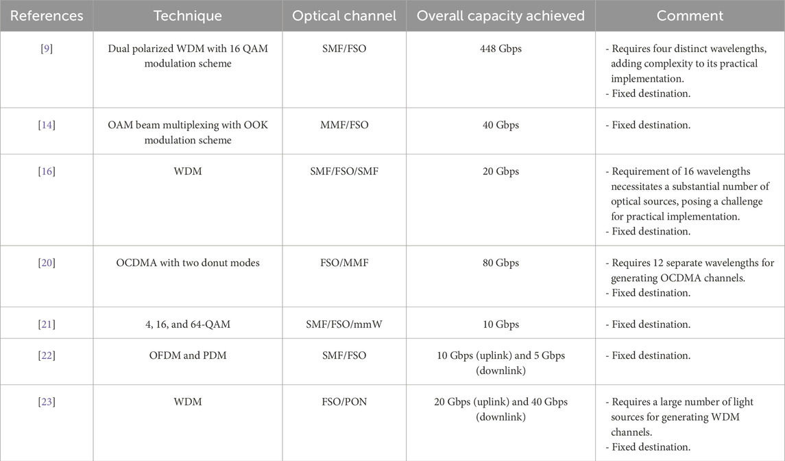
Table 1. Summary of related work
The main contributions of this study are as follows.
1. Hybrid optical communication framework. We propose a system supporting multiple users at different locations, addressing the limitation of prior research that assumed fixed user positions and identical transmission conditions.
2. Single-wavelength OAM-based multi-channel transmission. Four independent data streams are modulated onto OAM beams generated from a single 1,550-nm CW laser. The beams follow different paths: two traverse a clear-weather FSO link, one transitions from FSO to SMF, and one propagates through a fog-affected FSO link, enabling performance evaluation under varied conditions.
3. Performance analysis and evaluation. We analyze the effects of FSO divergence angle, SMF length, and propagation distance using BER, Q-factor, and eye diagrams. We also examine cascading FSO links, where the first link remains fixed and the subsequent link experiences varying fog densities, demonstrating the system’s feasibility and robustness.
The rest of this paper is organized as follows. Section 2 outlines the overall system architecture and its application framework. Section 3 details the design methodology, including key system components and operational principles. Section 4 presents performance evaluation, incorporating both theoretical analysis and mathematical modeling. Section 5 discusses the results, providing in-depth interpretation and insights. Finally, Section 6 summarizes the key findings and highlights potential directions for future research.
2 Applications for the proposed system
Figure 1 illustrates the layout of the proposed hybrid optical communication system designed to accommodate end users at different locations. The proposed hybrid optical communication system enables multi-destination connectivity by synergistically integrating FSO and fiber-based links. At the central office (CO), backbone network traffic is converted into four spatially orthogonal orbital angular momentum (OAM) modes (topological charges ℓ = 0, 15, 40, 70) generated from a single continuous wave (CW) source (1,550 nm) using a cascaded phase-patterned spatial light modulator (SLM). These beams are visually distinguished in Figure 1 as brown for ℓ = 0, green for ℓ = 15, red forℓ = 40, and cyan for ℓ = 70. These modes are multiplexed and transmitted over an FSO channel to the optical wireless unit (OWU), which acts as a distribution hub.
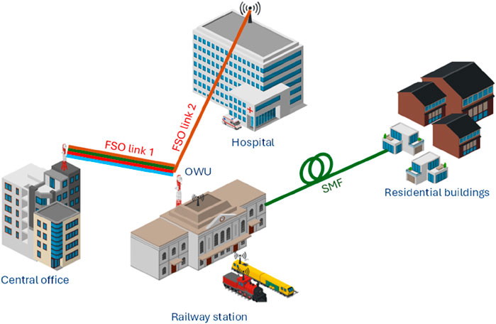
Figure 1. Layout of proposed hybrid optical communication system enabling multi-destination connectivity.
At the OWU, the received composite beam is demultiplexed into four independent OAM channels. Two co-located destinations (topological charges ℓ = 40, 70)—a railway station and a company—are directly served by the OWU. For the remaining two destinations, the third, a residential building, is connected via a SMF link (ℓ = 15), and for the fourth destination, a hospital, the OAM channel (ℓ = 0) is propagated through a secondary FSO link.
3 Proposed different integrated optical communication system
Figure 2 displays the schematic diagram for the proposed hybrid optical communication system.
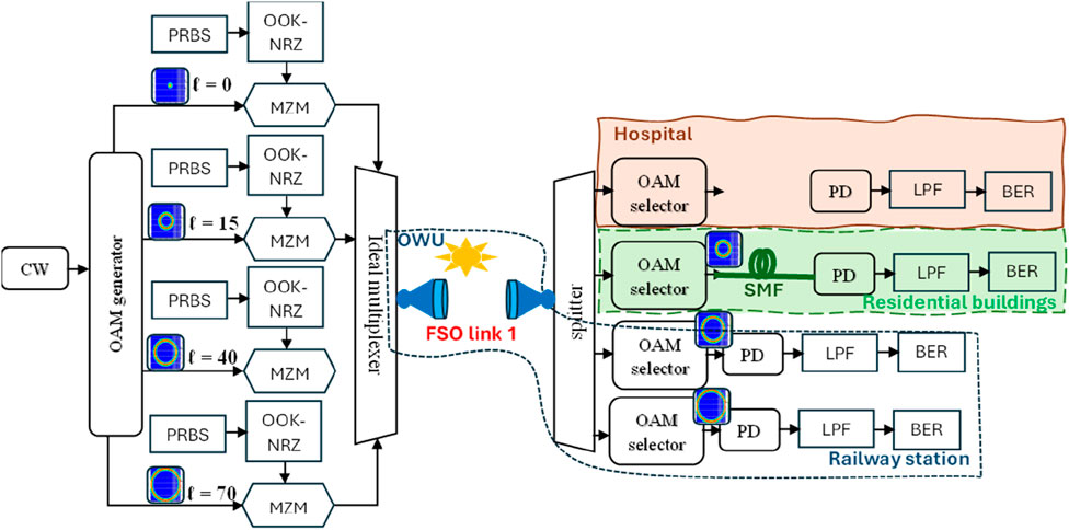
Figure 2. Schematic diagram of proposed hybrid optical communication system enabling multi-destination connectivity.
3.1 Transmitter
At the transmitter, a CW source operating at 1,550 nm is utilized, followed by an OAM generator for producing four distinct OAM beams with topological charges ℓ = 0, 15, 40, and 70 which act as optical carriers. The selection of these ℓ values ensures wide separation among OAM modes to facilitate accurate classification. Each optical carrier is modulated with data generated from a pseudo-random-bit-sequence generator (PRBSG) using ON-OFF keying with non-return-to-zero (OOK-NRZ) line coding at 10 Gbps. A Mach–Zehnder modulator (MZM) is used to imprint the electrical signal onto each OAM beam. The modulated OAM beams are then multiplexed and transmitted through the FSO channel.
3.2 Channel
Clear weather with attenuation 0.14 dB/km is considered in this FSO channel [16].
3.3 Receiver
The received signal after propagating through the first FSO channel is demultiplexed by a spatial demultiplexer to four OAM beams. The information carried by these beams is received at different destinations as follows.
- The two OAM beams with ℓ = 40 and 70 are passed through a photodiode (PD) detector to return signal in electrical form and are then filtered by low-pass-filter (LPF) to block the unwanted signal and then further undergo a BER analyzer to show the eye diagram and evaluate the BER and Q-factor for the received data at the end users.
- The third beam with ℓ = 15 continues transmitting in SMF fiber until reaching the receiver side. At the receiver, the resultant received optical signal is converted to electrical domain through PD and filtered by LPF and finally passed to the BER analyzer.
- The fourth beam with ℓ = 0 is directly connected to the second FSO channel which is exposed to foggy weather conditions until reaching its destination. After being received, it passes through PD, LPF, and a BER analyzer.
4 Performance analysis
Equation 1 shows the output electric field from the CW and is expresses as follows:
where
Each of the four OAM beams with radial index
where
The
where
The optical field at the output of the
where
After ideal multiplexing of four OAM channels before propagating through first FSO channel, the combined optical signal is given in Equation 5 as
We assume perfect orthogonality and no inter-channel interference between the OAM modes.
The received signal after propagating through the first FSO channel has optical received power given in Equation 6 as [24–27]:
where
After demultiplexing, Equation 7 shows the received optical power for each OAM beam is given as
where
where
The photocurrent for the
where
Equation 10 shows the total variance at the PD output as [28]
where
Hence, the SNR for the
The BER based on Gaussian approximation can be calculated using Equation 12 in terms of SNR as [28]
where
Additionally, BER is given in terms of Q-factor using Equation 13 as [28]
Table 2 shows the values of parameters used in Optisystem software Ver. 21 and MATLAB 2023b for obtaining the results of the proposed system [23–27].
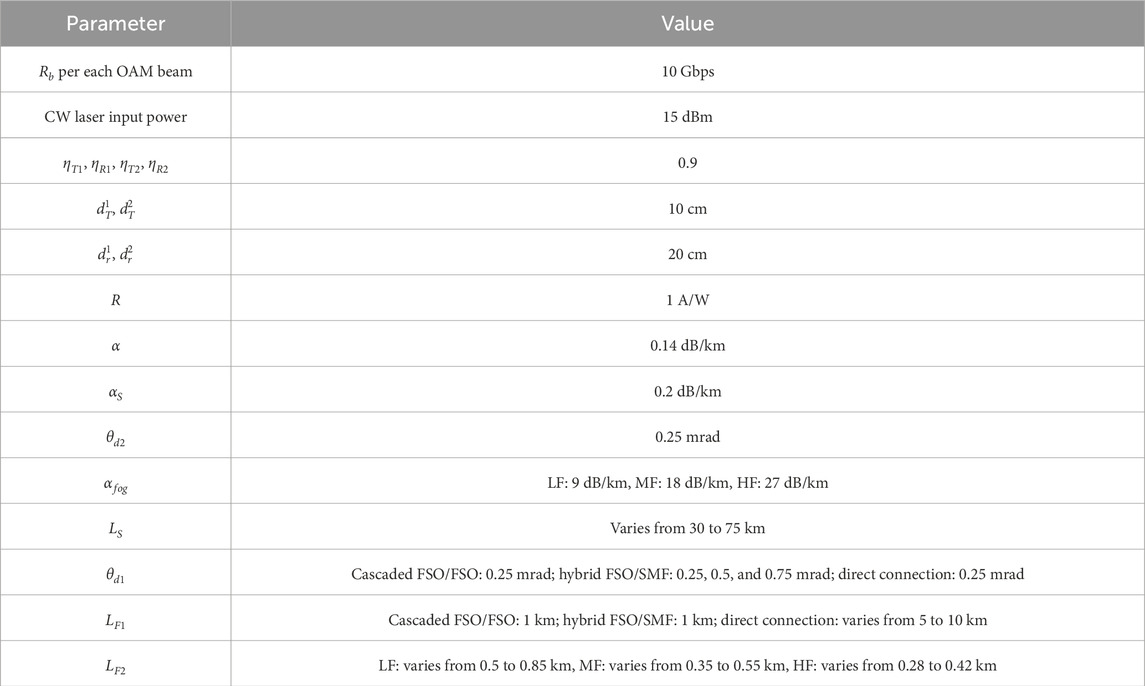
Table 2. Parameters with values
5 Simulation results and discussion
This section discusses the system’s performance across three receiver locations.
a. Cascaded FSO/FSO Under Fog Conditions (ℓ = 0 traversing two FSO links)
In this subsection, we analyze the performance of the single OAM beam out of the four that propagated through the dual-channel FSO system. The first FSO channel was fixed at 1 km under clear weather conditions with an attenuation of 0.14 dB/km. In contrast, the second FSO channel was evaluated under various fog conditions, and the performance of the
Figure 3 illustrates the BER performance of the
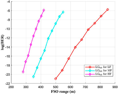
Figure 3. log (BER) of OAM beam (ℓ = 0) of the proposed system in case of cascaded FSO/FSO versus FSO ranges of the second channel.
Figure 4 demonstrates the Q-factor performance of the
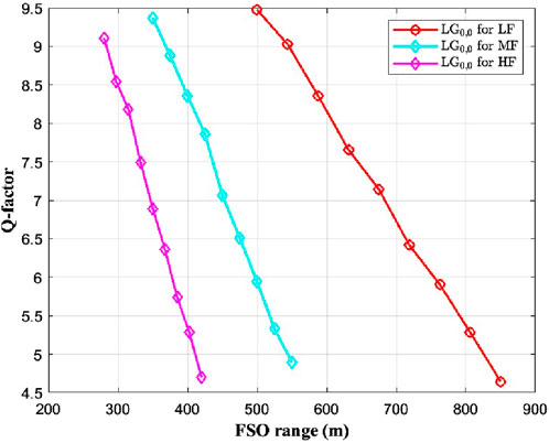
Figure 4. Q-factor of OAM beam (ℓ = 0) of the proposed system in the case of cascaded FSO/FSO versus FSO ranges of the second channel.
Figure 5 presents the eye diagrams corresponding to overall transmission distances of 1.85 km (LF), 1.55 km (MF), and 1.42 km (HF) for data received on the OAM beam with ℓ = 0. The eye diagram illustrates how well the system can distinguish between binary ones and zeroes. The openness of the eye (vertical opening) reflects signal clarity and low BER, while the horizontal eye width indicates proper timing for bit detection. Jitter is observed as horizontal noise at bit transitions, and vertical noise relates to amplitude variations [29]. As shown in Figure 5, the eye diagram at a transmission distance of 850 m under LF conditions exhibits the widest eye opening, indicating minimal bit errors at the ideal sampling instance. A broader eye opening generally corresponds to reduced inter-symbol interference and lower error probability. The steepness of the diagram’s left and right edges reflects the signal’s rise and fall durations; shorter transitions imply a wider bandwidth and enhanced data throughput. Jitter, which is quantified by the horizontal spread at the crossing points of the bit transitions, provides additional indication of potential timing errors. The extinction ratio, on the other hand, is linked to the system’s power efficiency, while the bit rate can be determined by taking the reciprocal of the bit duration. The pronounced eye openings at these distances indicate successful reception of data transmitted at 10 Gbps.
b. Hybrid FSO/SMF Transmission (ℓ = 15 transitioning to SMF after fixed FSO span of 1 km)
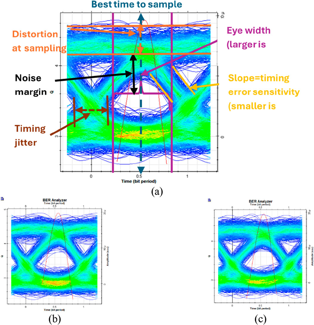
Figure 5. Eye diagrams for data received on OAM beam (ℓ = 0) of the proposed system in the case of cascaded FSO/FSO at overall FSO ranges of (a) 1.85 km under LF; (b) 1.55 km under MF, and (c) 1.42 km under HF.
The performance of the OAM beam where ℓ = 15 is discussed now. The beam first traveled a fixed range of 1 km in FSO range with various SMF lengths. Its performance is investigated at various beam divergence angles and different SMF lengths in terms of BER, Q-factor, and beam divergence.
This section analyzes the performance of an OAM beam with ℓ = 15 over a 1-km FSO link considering various SMF lengths. Performance is evaluated in terms of BER, Q-factor, and beam divergence at different divergence angles of FSO channel and SMF lengths.
Figures 6 and 7 present a comparative analysis of the BER and Q-factor for the
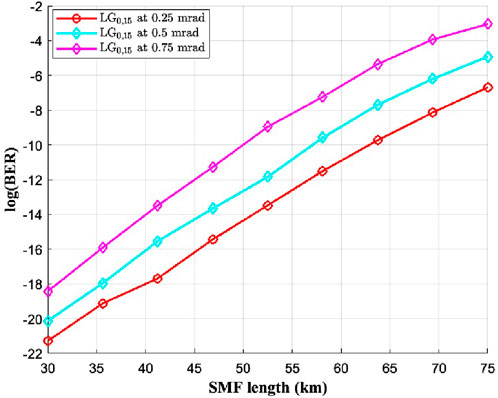
Figure 6. log (BER) of OAM beam (ℓ = 15) of the proposed system in the case of hybrid FSO/SMF versus SMF lengths at different beam divergence angles of FSO channel.
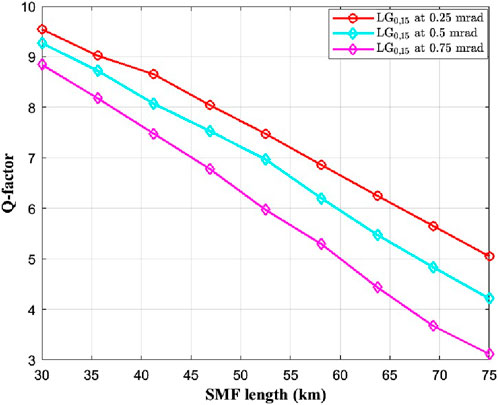
Figure 7. Q-factor of OAM beam (ℓ = 15) of the proposed system in the case of hybrid FSO/SMF versus SMF lengths at different beam divergence angles of FSO channel.
Figure 8 presents the eye diagrams for the
c. Direct FSO Reception (ℓ = 40, 70 after first FSO channel)
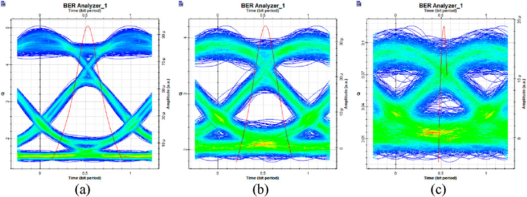
Figure 8. Eye diagrams for data received on OAM beam (ℓ = 15) of the proposed system in case of hybrid FSO/SMF at overall transmission distance of 76 km for beam divergence angles of (a) 0.25 mrad, (b) 0.5 mrad, and (c) 0.75 mrad.
This subsection examines the performance of two OAM beams with azimuthal indices where ℓ = 40 and 70 under clear weather conditions. Figures 9 and 10 illustrate the BER and Q-factor for the
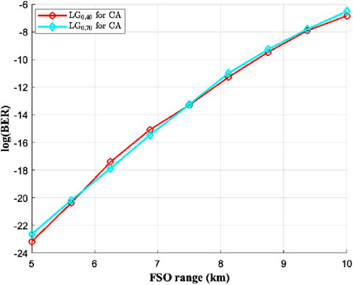
Figure 9. log (BER) of OAM beams (ℓ = 40 and 70) of the proposed system in the case of direct link versus FSO ranges.
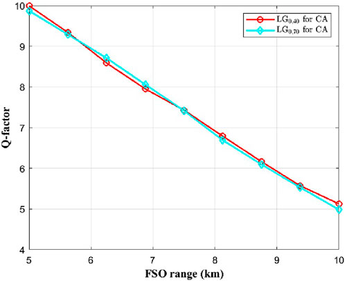
Figure 10. Q-factor of OAM beams (ℓ = 40 and 70) of the proposed system in the case of direct link versus FSO ranges.
Finally, the eye diagrams for two OAM beams (
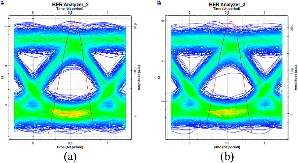
Figure 11. Eye diagrams at 10 km in the case of direct link for two OAM beams: (a)
Table 3 compares previous studies with the proposed work in terms of the technique used, optical channel, receiver location, overall capacity achieved, and the BER and Q-factor values obtained.
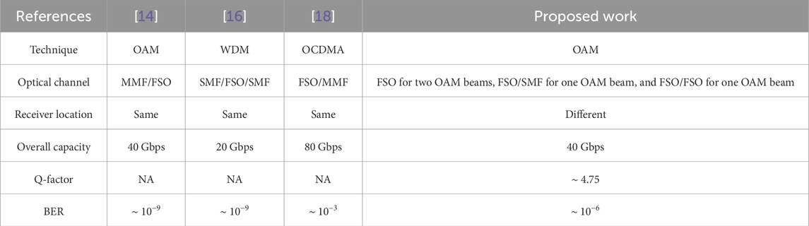
Table 3. Comparison between previous studies and proposed work
6 Conclusion
This study introduced a hybrid optical communication system that leverages OAM beam multiplexing to enhance data transmission across distinct propagation environments. By integrating FSO and SMF links, the proposed architecture effectively supports multiple users under varying atmospheric and channel conditions. The system design enables independent data streams to propagate through different paths, including direct FSO reception, hybrid FSO-SMF transmission, and cascaded FSO links affected by fog.
Comprehensive performance analysis revealed the impact of transmission distance, divergence angle, and channel attenuation on system reliability. The results demonstrated robust signal integrity under clear conditions and quantified degradation under fog, highlighting the trade-offs between propagation range and signal quality. Moreover, the hybrid FSO-SMF configuration maintained acceptable BER performance over extended fiber spans, validating its feasibility for long-haul applications.
Overall, this work contributes to the advancement of scalable and adaptable optical networks, offering promising solutions for diverse communication scenarios, including urban connectivity and emergency response systems. Future investigations may focus on optimizing beam alignment, mitigating turbulence effects, and extending system capabilities to accommodate higher data rates and additional multiplexing techniques.
7 Future directions/research challenges and opportunities
Future research can enhance hybrid optical communication by addressing turbulence, weather effects, and mitigation techniques. Implementing advanced error correction, adaptive modulation, and security enhancements such as quantum key distribution (QKD) will improve reliability. Furthermore, experimental validation through laboratory and field trials is necessary to refine system parameters and confirm theoretical findings under practical conditions. Expanding the framework to support multi-hop relay-assisted communication would improve reliability and extend coverage in large-scale optical networks. Future studies may also explore the integration of this hybrid system with emerging technologies such as intelligent reflecting surfaces (IRS) and reconfigurable optical networks to optimize signal propagation and enhance overall system performance. Addressing these challenges will contribute to the advancement of high-capacity, secure, and adaptive optical communication systems for next-generation terrestrial hybrid optical channels networks and beyond.
Data availability statement
The original contributions presented in the study are included in the article/supplementary material; further inquiries can be directed to the corresponding author.
Author contributions
MS: Conceptualization, Formal Analysis, Investigation, Writing – original draft. SA: Conceptualization, Investigation, Methodology, Writing – original draft, Supervision, Writing – review and editing. MA: Formal Analysis, Methodology, Supervision, Writing – review and editing. KA: Project administration, Supervision, Validation, Writing – review and editing. AA: Funding acquisition, Project administration, Resources, Supervision, Validation, Writing – review and editing.
Funding
The author(s) declare that financial support was received for the research and/or publication of this article. This work was funded by the Deanship of Graduate Studies and Scientific Research at Jouf University under grant No. (DGSSR-2025-FC-01078).
Conflict of interest
The authors declare that the research was conducted in the absence of any commercial or financial relationships that could be construed as a potential conflict of interest.
Generative AI statement
The author(s) declare that no Generative AI was used in the creation of this manuscript.
Any alternative text (alt text) provided alongside figures in this article has been generated by Frontiers with the support of artificial intelligence and reasonable efforts have been made to ensure accuracy, including review by the authors wherever possible. If you identify any issues, please contact us.
Publisher’s note
All claims expressed in this article are solely those of the authors and do not necessarily represent those of their affiliated organizations, or those of the publisher, the editors and the reviewers. Any product that may be evaluated in this article, or claim that may be made by its manufacturer, is not guaranteed or endorsed by the publisher.
References
1. Dai M, Sun G, Yu H, Wang S, Niyato D. User association and channel allocation in 5G Mobile asymmetric multi-band heterogeneous networks. IEEE Trans Mobile Comput (2025) 24(4):3092–109. doi:10.1109/TMC.2024.3503632
2. Jun J, Shuli S, Weili Z, Jialong L, Na C, Hongzhan Z, et al. Quantitative analysis of the tropospheric delay differences for 1–300 GHz microwave signals with ground-based microwave radiometric profiles. Adv Spacers (2024) 74:105–16. doi:10.1016/j.asr.2024.03.051
3. Zhou G, Xu J, Hu H, Liu Z, Zhang H, Xu C, et al. Off-axis four-reflection optical structure for lightweight single-band bathymetric LiDAR. IEEE Trans Geosci Remote Sensing (2023) 61:1–17. doi:10.1109/TGRS.2023.3298531
4. Goel A, Upadhya A, Dwivedi VK. Diversity aided millimeter-wave/free space optical cooperative relaying systems. J Commun Syst (2021) 34:e4700. doi:10.1002/dac.4700
5. Le HD, Pham AT. Link-layer retransmission-based error-control protocols in FSO communications: a survey. IEEE Commun Surv Tutor (2022) 24:1602–33. doi:10.1109/comst.2022.3175509
6. Yang X, Zhuang Y, Shi M, Sun X, Cao X, Zhou B. RatioVLP: ambient light noise evaluation and suppression in the visible light positioning system. IEEE Trans Mobile Comput (2024) 23(5):5755–69. doi:10.1109/TMC.2023.3312550
7. Zhou G, Zhou X, Li W, Zhao D, Song B, Xu C, et al. Development of a lightweight single-band bathymetric LiDAR. Remote Sensing (2022) 14(22):5880. doi:10.3390/rs14225880
8. Rademacher G. The future of optical communications. In: T Kawanishi, editor. Handbook of radio and optical networks convergence. Singapore: Springer (2023). doi:10.1007/978-981-33-4999-5_22-1
9. Singh M, Aly MH, El-Mottaleb SAA. Performance analysis of a 448 gbps PDM/WDM/16-QAM hybrid SMF/FSO system for last mile connectivity. Opt Quan Electronics (2023) 55(3):231. doi:10.1007/s11082-022-04534-6
10. Abd El-Mottaleb S, Fayed H, Abd El-Aziz A, Metawee M, Aly M. Enhanced spectral amplitude coding OCDMA system utilizing a single photodiode detection. Appl Sci (2018) 8(10):1861. doi:10.3390/app8101861
11. Ma P, Yao T, Liu W, Pan Z, Chen Y, Yang H A 7-kW narrow-linewidth fiber amplifier assisted by optimizing the refractive index of the large-mode-area active fiber. High Power Laser Sci Eng (2024) 12:e67. doi:10.1017/hpl.2024.41
12. Guan B, Scott RP, Qin C, Fontaine NK, Su T, Ferrari C, et al. Free-space coherent optical communication with orbital angular, momentum multiplexing/demultiplexing using a hybrid 3D photonic integrated circuit. Opt Express (2014) 22:145–56. doi:10.1364/oe.22.000145
13. Guan Z, Zuo T, Xie C, Huang L, Wen K, Wang C, et al. Orbital angular momentum mode multiplexing communication in multimode fibers. Opt Commun (2024) 569:130857. doi:10.1016/j.optcom.2024.130857
14. Singh M, Abd El-Mottaleb SA, Alwee Aljunid S, Yousif Ahmed H, Zeghid M, Nisar KS. Performance investigations on integrated MMF/FSO transmission enabled by OAM beams. Results Phys (2023) 51:106656. doi:10.1016/j.rinp.2023.106656
15. Allen L, Beijersbergen MW, Spreeuw RJC, Woerdman JP. Orbital angular momentum of light and the transformation of laguerre–gaussian laser modes. Phys Rev A (1992) 45:8185–9. doi:10.1103/physreva.45.8185
16. Gupta A, Singh S, Singh H. Designing of hybrid optical fiber/MIMO-FSO system for offering high-speed connectivity to the last mile users. Opt Quant Electron (2024) 56:1088. doi:10.1007/s11082-024-07011-4
17. Esmail MA. Performance monitoring of hybrid all-optical Fiber/FSO communication systems. Appl Sci (2023) 13:8477. doi:10.3390/app13148477
18. Yang X, Zhang H, Zhuang Y, Wang Y, Shi M, Xu Y. uLiDR: an inertial-assisted unmodulated visible light positioning system for smartphone-based pedestrian navigation. Inf Fusion (2025) 113:102579. doi:10.1016/j.inffus.2024.102579
19. Zhou Y, Lin X, Xu Z, Lu Z, Huang Y, Luo Z, et al. Beyond 600Gbps optical interconnect utilizing wavelength division multiplexed visible light laser communication. Chinese Optics Letters (2025). doi:10.3788/COL202523.050002
20. Kumari M, Sharma A, Chaudhary S. High-speed spiral-phase donut-modes-based hybrid FSO-MMF communication system by incorporating OCDMA scheme. Photonics (2023) 10(1):94. doi:10.3390/photonics10010094
21. Nguyen D-N, Bohata J, Komanec M, Zvanovec S, Ortega B, Ghassemlooy Z. Seamless 25 GHz transmission of LTE 4/16/64-QAM signals over hybrid SMF/FSO and wireless link. J Lightwave Technology (2019) 37(24):6040–7. doi:10.1109/jlt.2019.2945588
22. Mukherjee R, Mallick K, Mandal P, Dutta B, Kuiri B, Patra AS. Bidirectional hybrid OFDM based free-space/wireless-over-fiber transport system. Opt Quant Electron (2020) 52:311–22. doi:10.1007/s11082-020-02428-z
23. Mandal P, Sarkar N, Santra S, Dutta B, Kuiri B, Mallick K, et al. Hybrid WDM-FSO-PON with integrated SMF/FSO link for transportation of Rayleigh backscattering noise mitigated wired/wireless information in long-reach. Opt Commun (2022) 507:127594–5804. doi:10.1016/j.optcom.2021.127594
24. Shakthi Murugan KH, Sharma A, Malhotra J. Performance analysis of 80 Gbps Ro-FSO system by incorporating hybrid WDM-MDM scheme. Opt Quant Electron (2020) 52:505. doi:10.1007/s11082-020-02613-0
25. Mohamed AG, Abd El-Mottaleb SA, Singh M, Yousif Ahmed H, Zeghid M, Abdulkawi WM, et al. Chaos fractal digital image encryption transmission in underwater optical wireless communication system. IEEE Access (2024) 12:117541–59. doi:10.1109/ACCESS.2024.3446836
26. Kim I, Korevaar E. Availability of free space optics (FSO) and hybrid FSO/RF systems. Proc SPIE Opt Wireless Commun IV (2001) 530:84–95. doi:10.1117/12.449800
27. Xu Z, Lin X, Luo Z, Lin Q, Zhang J, Wang G, et al. Flexible 2 × 2 multiple access visible light communication system based on an integrated parallel GaN/InGaN micro-photodetector array module. Photon Res (2024) 12(4):793–803. doi:10.1364/PRJ.517212
28. Singh M, Atieh A, Aly MH, Abd El-Mottaleb SA. 120 Gbps SAC-OCDMA-OAM-based FSO transmission system: performance evaluation under different weather conditions. Alexandria Eng J (2022) 61:10407–18. doi:10.1016/j.aej.2022.03.070
Keywords: free space optics, single-mode fiber, orbital angular momentum multiplexing, bit error rate, attenuation
Citation: Singh M, Abd El-Mottaleb SA, Alsharari M, Aliqab K and Armghan A (2025) Hybrid optical communication systems leveraging orbital angular momentum multiplexing: multi-user access and performance analysis under diverse transmission scenarios. Front. Phys. 13:1581549. doi: 10.3389/fphy.2025.1581549
Received: 22 February 2025; Accepted: 15 August 2025;
Published: 17 September 2025.
Edited by:
Muhammad Saadi, Nottingham Trent University, United KingdomReviewed by:
Shuang Chang, Vanderbilt University, United StatesSushank Chaudhary, Guangdong University of Petrochemical Technology, China
Jawwad Chattha, University of Management and Technology, Lahore, Pakistan
Muhammad Kamran Saleem, University of Central Punjab, Pakistan
Copyright © 2025 Singh, Abd El-Mottaleb, Alsharari, Aliqab and Armghan. This is an open-access article distributed under the terms of the Creative Commons Attribution License (CC BY). The use, distribution or reproduction in other forums is permitted, provided the original author(s) and the copyright owner(s) are credited and that the original publication in this journal is cited, in accordance with accepted academic practice. No use, distribution or reproduction is permitted which does not comply with these terms.
*Correspondence: Meshari Alsharari, bW1hYWxzaGFyYXRpQGp1LmVkdS5zYQ==