 Yanchen Liu
 Renrong Li*
- College of Civil Engineering, Jiangsu Open University, Nanjing, China
Retaining walls are usually located next to existing structures. This runs counter to the traditional theoretical presumption of semi-infinite space, making it unsuitable to continue applying Coulomb’s theory. In order to design retaining walls with narrow backfill, improving the established theory and seeking an economical design theory are necessary. This paper puts forward an analytical approach for estimating the active earth pressure of narrow backfills. The approach, based on the slice-element method, takes into account the arching effect. The results obtained are verified through centrifuge tests, numerical computations, and analytical methods. Additionally, parametric studies are conducted to gain a comprehensive understanding of problems related to earth pressure. These studies consider how sensitive design variables, such as the soil friction angle, the wall–soil interface friction angle, and the aspect ratio, influence the active thrust coefficient and the height of the application point of the active thrust from the base. To enable the practical utilization of this analytical approach, a simplified design table related to the standard Coulomb solutions is provided at the end.
1 Introduction
Retaining walls are mainly used to prevent the fill from slipping or collapsing and ensure the stability and safety of the structure. Earth pressure calculation is an important part of retaining wall design. Traditionally, the active earth pressure acting on rigid retaining walls is computed using Coulomb’s or Rankine’s theory [1, 2]. It is assumed that the active earth pressure along the wall is distributed linearly. However, several studies indicate that the distribution of active earth pressure is non-linear for rough walls [3–5]. This difference between linear and non-linear distributions of earth pressure is mainly due to the wall–soil interface friction angle [6].
The above-mentioned methods are based on the assumptions that the backfill behind the rigid wall extends to a sufficient distance and the sliding plane is fully developed in the backfill. However, retaining walls are constructed adjacent to existing structures or near the rock faces in practical applications, and the backfill behind the wall is of finite width [7]. This conflicts with the assumption of a triangular thrust wedge formed in a soil mass within the semi-infinite space. This may be because the thrust wedge fails to form in the shape and size anticipated by these methods. Therefore, a new analytical approach needs to be presented to more precisely estimate the active earth pressure against rigid walls with narrow backfills.
Previous centrifuge tests have been performed to measure lateral earth pressures behind retaining walls with narrow backfills. The results show that the wall–soil interface friction leads to a rotation of the principal stresses, which causes an arching effect. This leads to a non-linear distribution of earth pressures behind the wall, and the total lateral earth pressure is less than that predicted through conventional methods [8, 9]. The results of field monitoring proved this phenomenon [10]. The arching effect in narrow backfills has a more pronounced effect on the earth pressure distribution. The particle image velocity (PIV) technique has been introduced into model tests to study the distribution of soil stresses at different aspect ratios, which confirms the existence of the soil arch effect [11, 12]. Nevertheless, the progression of experiments has been rather tepid. The root causes lie in the increasing complexity of simulated working conditions and the substantial cost of resources.
Considering the above-mentioned shortcomings, many studies have used cost-effective and powerful numerical tools, such as the finite element method (FEM) [13, 14], the discrete element method (DEM) [15, 16], and finite-element limit analysis (FELA) [17, 18]. Numerical calculations are usually carried out for specific conditions and are more demanding on engineers. Therefore, they are not suitable for widespread use in engineering.
Many analytical methods have been used to estimate the active earth pressures on retaining walls with narrow backfills; the limit equilibrium method and slice-element method are two representative calculation methods. The first method has been used to calculate the total horizontal earth pressure with multiple slip surfaces, but this method was unable to obtain the distribution of earth pressures [19]. Recently, the finite-difference theorem has been used to compensate for the shortcomings [20, 21]. The distribution of earth pressure behind the wall can be easily obtained using the slice-element method [22]. In-depth analytical studies on retaining structures have been conducted, leading to proposed reinforcement strategies and guidelines for soil pressure analysis [23–25]. To estimate the distribution of pressure inside a narrow backfill, an approach for computing the active pressure in a two-dimensional stress solution was presented [26]. This method assumes that the vertical stress σz does not vary with the width of the backfill, while it is not completely independent of the width of the backfill in reality. The influence of the width of the backfill on σz cannot be ignored. Although existing methods provide theoretical solutions, the complex computational processes limit the practical engineering applications.
This study investigates a rigid retaining wall of height H supporting a cohesionless narrow backfill of width B. Key parameters include the soil internal friction angle
2 Proposed analytical methods
Figure 1A shows an analysis model considering both principal stress transfer mechanisms and failure mechanisms. The model can be used to research the active earth pressure of the narrow cohesionless backfill. The sliding plane intersects with the opposite wall (or rock face), and the depth of intersection from the wall top
where H is the height of the retaining wall, B is the width of the narrow backfill, and α is the rupture angle, which is discussed below.
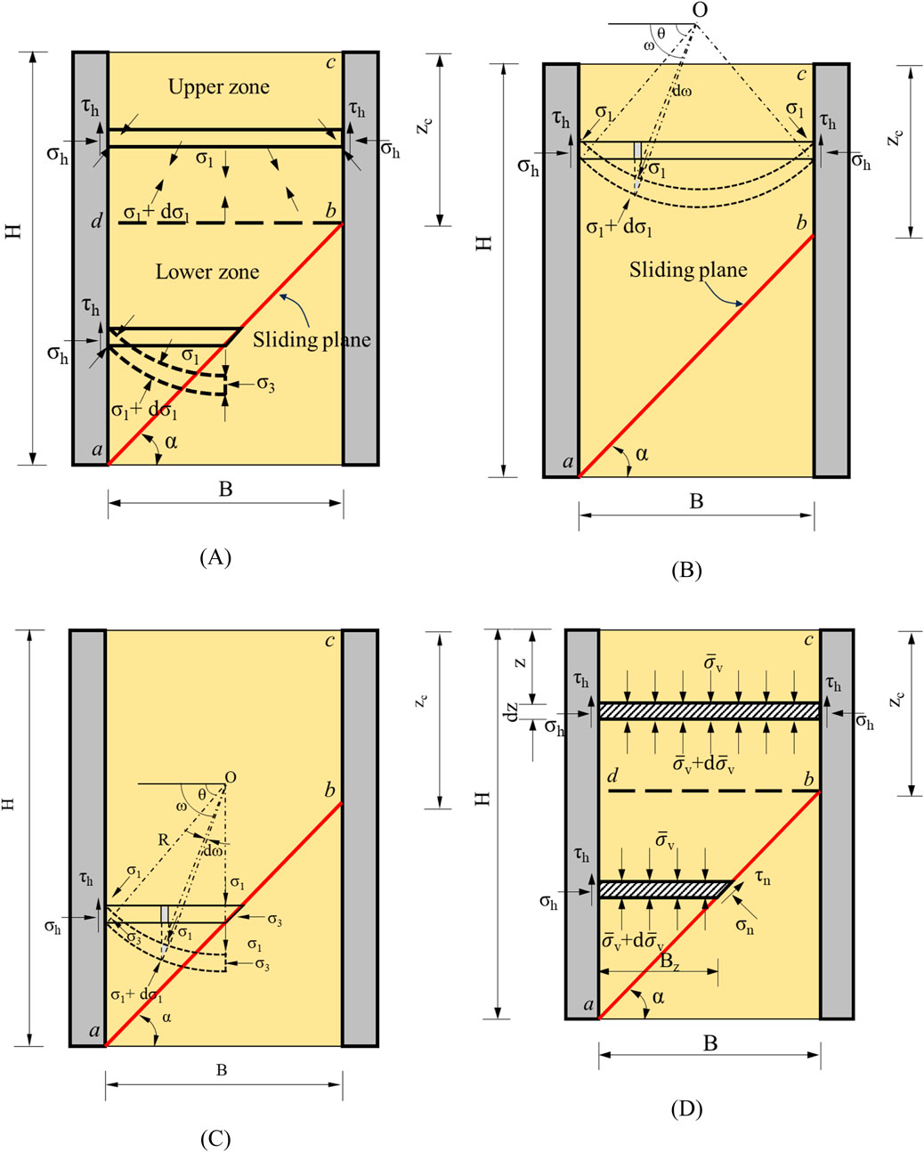
Figure 1. Sliding model for active earth pressure with a narrow fill: (A) trajectory of minor principal stresses, (B) calculation model in the upper zone, (C) calculation model in the lower zone, and (D) free-body diagram of the slice element.
Some basic assumptions are made to simplify the analysis as follows:
(1) The backfill is cohesionless and meets the Mohr–Coulomb failure criterion.
(2) The movement of retaining walls is sufficient to cause the limit state of soil and full mobilization of wall–soil interface strength.
(3) The failure surface consists of two planes: ab and bc. The rupture angle α (angle between the slip surface ab and the horizontal plane) can be determined using Coulomb’s theory, as shown in Equation 2 [27]:
where φ is the soil friction angle and δ is the wall–soil interface friction angle.
(4) The trajectories of minor principal stresses in the upper and lower zones (as shown in Figure 1A) are assumed to be circular arcs [28].
2.1 Upper zone
In the upper zone, the slice element is rectangular, as shown in Figures 1B,D, and the lateral earth pressure
where r is the unit weight of the backfill and z is the distance from the top of the wall.
In Equation 5,
where
2.2 Lower zone
In the lower zone, the slice element is trapezoidal, as shown in Figures 1C,D. By summing the vertical forces acting on the slice element, Equation 8 can be obtained:
where
where C is an integration constant. It is considered a boundary condition that the average vertical stress
Therefore, the particular solution to this differential equation (Equation 8) in the lower zone can be calculated as follows:
The lateral earth stress at any depth acting on the wall in the lower zone can be calculated by multiplying Equation 11 by
2.3 Magnitude and height of application of the lateral active force
The magnitude of lateral earth pressure exerted on the wall can be calculated using Equation 13:
The moment generated by the lateral earth pressure on the wall can be calculated using the following Equation 14:
The modified active earth pressure coefficient K was determined through back-calculation, as shown in Equation 15:
The height of application of the lateral active force h can be calculated using Equation 13 and Equation 14, as shown in Equation 16:
Based on Equation 15, when δ = 0°, the height of application of the lateral active force is one-third of the wall height. This is in agreement with the results obtained from Coulomb’s or Rankine’s theory [1, 2]. When
3 Comparison with previous studies
To verify rationality and accuracy, the proposed method is compared with results from previous geotechnical centrifuge tests, FEM, and analytical solutions in terms of
Figure 2 shows a comparison between the results obtained by the proposed analytical method and those obtained from centrifuge tests, numerical calculations, and existing analytical methods. Considering the diverse aspect ratios comprehensively examined through centrifuge tests, the proposed solutions agree well with the results from centrifuge tests. The proposed analytical method is smaller than the Coulomb solution based on infinite space; this may be because the sliding wedge fails to develop fully in the narrow backfill. The differences among the existing solutions suggest that the assumption of semi-infinite backfill space may not be suitable for the economic design of retaining walls with narrow cohesionless backfills.
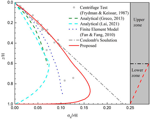
Figure 2. Comparison of the results obtained by the proposed analytical method with those of the centrifuge test, numerical calculation, and existing analytical method.
4 Parametric studies
In this section, a parametric study of the proposed analytical method was conducted. Sensitive influencing parameters were chosen, such as the soil friction angle φ, the wall–soil interface friction angle δ, and the aspect ratio B/H. Calculations were carried out for the height of the application point of active thrust to the base h/H, the active thrust coefficient K, and the normalized horizontal active earth pressure distribution
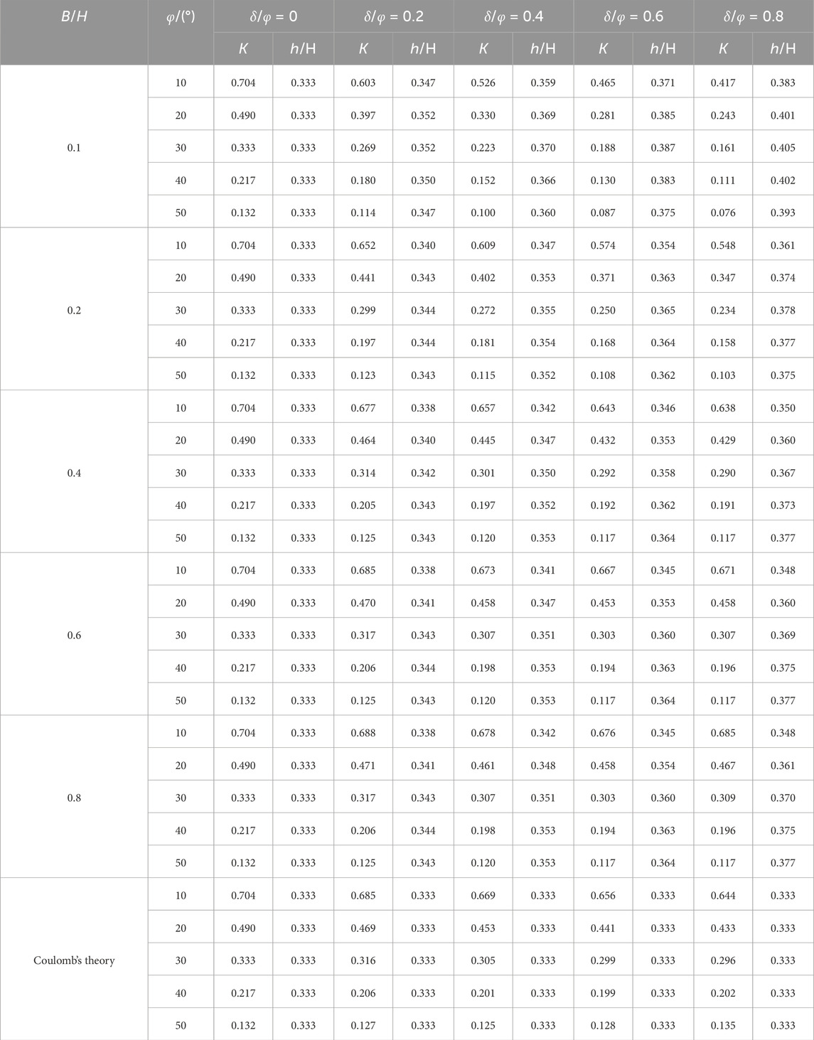
Table 1. Modified active earth pressure coefficient and the height of the application point of active thrust involved in retaining walls with cohesionless backfills.
4.1 Effect of the soil friction angle
The change in the height of the application point of active thrust h/H and the active thrust coefficient K with the soil friction angle φ under different aspect ratios B/H are shown in Figures 3A,B, respectively. It should be noted that the ratio of the wall–soil interface friction angle to the soil friction angle δ/φ is fixed at 0.8 for the investigation of the effect of the soil friction angle. Figure 3A shows that the height of the application point of active thrust h/H obtained by the proposed method is approximately distributed in the range of 0.35H–0.43H, which is slightly higher than that of Coulomb’s theory, and the height of the application point of active thrust h/H is not much affected by the change in the soil friction angle φ for the case of a fixed aspect ratio B/H. The aspect ratio B/H gradually increases with the decrease in the height of the application point of active thrust h/H and is close to the assumption of infinite space. In Figure 3B, due to the arching effect, the active thrust coefficient K decreases in a concave curve with the soil friction angle φ. For a given soil friction angle φ, the larger the aspect ratio B/H, the larger the active thrust coefficient K in a narrow cohesionless backfill. When B > H cotα,
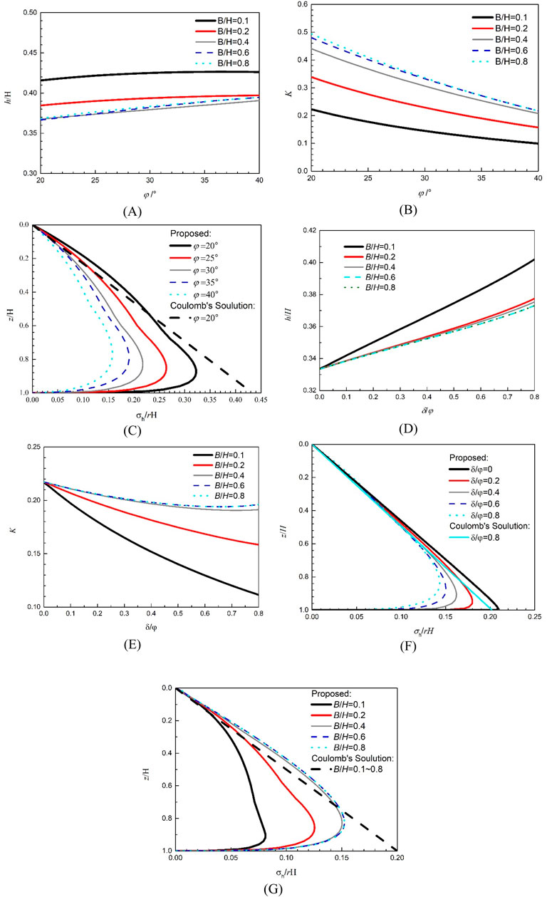
Figure 3. Sensitivity analysis of different parameters: (A) effect of the soil friction angle on the normalized height of the application point of active thrust, (B) effect of the soil friction angle on the active thrust coefficient, (C) effect of the soil friction angle on the active earth pressure distribution, (D) effect of the wall–soil interface friction angle on the normalized height of the application point of active thrust, (E) effect of the wall–soil interface friction angle on the active thrust coefficient, (F) effect of the wall–soil interface friction angle on the active earth pressure distribution, and (G) effect of the aspect ratio on the active earth pressure distribution.
Figure 3C shows the variation in the normalized horizontal active earth pressure
4.2 Effect of the wall–soil interface friction angle
Figures 3D,E show the change in the height of the application point of active thrust h/H and the active thrust coefficient K with the wall–soil interface friction angle δ under different aspect ratios B/H, respectively. It should be noted that the soil friction angle φ is fixed at 40° for the investigation of the effect of the wall–soil interface friction angle. Figure 3D shows the height of the application point of active thrust h/H obtained by the proposed method, and the approximate range is 0.33H–0.41H, which is similar to Figure 3A. When the wall–soil interface friction angle δ is 0, the height of the application point of active thrust h/H coincides with Coulomb’s theory. Figure 3E shows that the active thrust coefficient K decreases with the increase in the wall–soil interface friction angle δ for a narrow backfill. When B/H >0.4, the decreasing trend slows down. When the wall–soil interface friction angle δ is kept constant, the active thrust coefficient K increases with aspect ratios B/H first and then remains constant. When B/H >0.6, the active thrust coefficient K is not affected by aspect ratios B/H because a complete triangular thrust wedge can be formed.
Figure 3F shows the variation in the normalized horizontal active earth pressure
4.3 Effect of the aspect ratio
Assuming that the soil friction angle φ is 40° and the wall–soil interface friction angle δ is 0.8, the distribution of the horizontal soil pressure
At different aspect ratios B/H, the earth pressure increases with depth to a maximum value first and then decreases rapidly to 0. The depth of this maximum value decreases with the increase in the aspect ratio B/H. One reason may be that as the depth of the retaining wall increases, more vertical load is carried by the wall–soil friction [31]. All the above calculations show that the direct use of Coulomb’s theory without further modifications is not suitable for accurately estimating the active earth pressure on a retaining wall with a narrow backfill.
5 Simplified design methods
It is not very convenient to directly use Equations 12, 13, and 16 to calculate the active earth pressure in practice, which will greatly limit its practical application, and this is the reason why Coulomb’s theory is still widely used in geotechnical engineering design. Based on the above parameter analysis, the modified active earth pressure coefficient K and the height of the application point of active thrust h/H under different working conditions are summarized in Table 1. The Coulomb solution is also listed in Table 1 for comparison.
The ranges of values for the soil friction angle φ, the aspect ratio B/H, and the wall–soil interface friction angle δ were determined to satisfy engineering applications [27, 30]. Table 1 shows the variation in K and h/H with φ and δ/φ for various values of B/H. At δ/φ = 0, K is only relevant to φ, is independent of B/H, and is consistent with Coulomb’s theory. It can also be observed in the table that the value of K decreases with increasing φ at a rate that increases gradually with increasing φ. Table 1 shows that the height of the application point of active thrust h/H increases with δ/φ and decreases with φ. It can be observed that the height of the application point of active thrust h/H for δ/φ is 0·33, regardless of the internal friction angle φ and the aspect ratios B/H. This is consistent with Coulomb’s theory. It should be noted that when B/H > cotα, the triangular thrust wedge behind the rigid wall can develop fully so that K and h/H are no longer related to B/H, as shown in the gray part of Table 1. In Table 1, the earth pressure obtained by Coulomb’s theory does not consider the effect of B/H, and the earth pressure decreases significantly with the decrease in B/H, so Coulomb’s theory is more conservative. The earth pressure obtained by the proposed method is more reasonable. The active earth pressure of the narrow, cohesionless backfill against rigid walls can be obtained using Table 1, while cases involving unsaturated soils and passive earth pressures are not considered.
6 Conclusion
Most of the existing analytical methods for estimating active earth pressures on narrow retaining walls were complex, which hinders their application in practical engineering. In this paper, according to the slice-element method, a practical method is proposed to estimate the active earth pressure of the narrow cohesionless backfill against rigid walls, considering the arching effect. Results of the proposed analytical method are verified using centrifuge tests, numerical calculations, and existing analytical methods. A series of parametric studies revealed the effects of the soil friction angle φ, the wall–soil interface friction angle δ, and the aspect ratio B/H on the height of the application point of active thrust h/H, the modified active thrust coefficient K, and the normalized horizontal active earth pressure distribution
(1) The effect of the aspect ratio B/H on the modified active earth pressure coefficient K is significant. When B/H < cotα, K increases with increasing B/H at a rate that decreases gradually with increasing B/H. When B/H > cotα, the triangular thrust wedge behind the rigid wall can develop fully, and K and h/H no longer vary with B/H.
(2) For a given aspect ratio, the modified active thrust coefficient K decreases with the increasing soil friction angle φ and the wall–soil interface friction angle δ. Compared to their effect on K, φ and δ exhibit relatively minor influence on the height h/H, which reaches a maximum value approximately 30% larger than that calculated through Coulomb’s theory. The parameter h/H increases with φ first and then decreases with φ while showing a slight increasing trend with δ.
In this paper, the simplified earth pressure calculation method for retaining walls with a narrow backfill provides insights for the design of excavations close to basement walls, highways through mountainous terrains, and other projects, although several limitations cannot be neglected. This method may not be suitable for the case involving inclined rock or retaining walls since the difference in the interfacial behavior between the two retaining structures is neglected. Nevertheless, the proposed analytical method provides valuable guidance for the practical design of retaining walls with a narrow backfill.
Data availability statement
The original contributions presented in the study are included in the article/supplementary material; further inquiries can be directed to the corresponding author.
Author contributions
YL: Methodology, Writing – original draft. RL: Conceptualization, Funding acquisition, Writing – review and editing. YW: Validation, Writing – review and editing.
Funding
The author(s) declare that financial support was received for the research and/or publication of this article. This work was supported by the University Natural Science Foundation of Jiangsu Province (grant no. 24KJB560003) and the Science and Technology Projects of Jiangsu Province Construction System (grant no. 2024ZD038).
Conflict of interest
The authors declare that the research was conducted in the absence of any commercial or financial relationships that could be construed as a potential conflict of interest.
Generative AI statement
The author(s) declare that no Generative AI was used in the creation of this manuscript.
Publisher’s note
All claims expressed in this article are solely those of the authors and do not necessarily represent those of their affiliated organizations, or those of the publisher, the editors and the reviewers. Any product that may be evaluated in this article, or claim that may be made by its manufacturer, is not guaranteed or endorsed by the publisher.
References
1. Coulomb CA. Essai sur une application des règles de maximis and minimis à quelques problèmes de statique, relatifs à l'architecture. Paris: De l'Imprimerie Royale (1776).
2. Rankine WJM. On the stability of loose earth. Philos. Philosophical Trans R Soc Lond (1857) 147:9–27.
3. Paik KH, Salgado R. Estimation of active earth pressure against rigid retaining walls considering arching effects. Géotechnique (2003) 53(7):643–53. doi:10.1680/geot.2003.53.7.643
4. Li JP, Wang M. Simplified method for calculating active earth pressureon rigid retaining walls considering the arching effect under translational mode. Int J Geomechanics (2014) 14(2):282–90. doi:10.1061/(ASCE)GM.1943-5622.0000313
5. Cao WG, Liu T, Xu Z. Estimation of active earth pressure on inclined retaining wall based on simplified principal stress trajectory method. Int J Geomechanics (2019) 19(7):06019011. doi:10.1061/(ASCE)GM.1943-5622.0001447
6. Iskander M, Chen Z, Omidbar M, Guzman I, Elsherif O. Active static and seismic earth pressure for c-φ soils. Soils and Foundations (2013) 53(5):639–52. doi:10.1016/j.sandf.2013.08.003
7. Lai FW, Tschuchnigg F, Schweiger HF, Liu SY, Shiau J, Cai GJ. A numerical study of deep excavations adjacent to existing tunnels: integrating CPTU and SDMT to calibrate soil constitutive model. Can Geotechnical J (2025) 62:1–23. doi:10.1139/cgj-2024-0203
8. Frydman S, Keissar I. Earth pressure on retaining walls near rock faces. J Geotechnical Eng (1987) 113(6):586–99. doi:10.1061/(asce)0733-9410(1987)113:6(586)
9. Take WA, Valsangkar AJ. Earth pressures on unyielding retaining walls of narrow backfill width. Can Geotechnical J (2001) 38(6):1220–30. doi:10.1139/cgj-38-6-1220
10. O’Neal TS, Hagerty D. Earth pressures in confined cohesionless backfill against tall rigid walls—a case history. Can Geotechnical J (2011) 48(8):1188–97. doi:10.1139/t11-033
11. Khosravi MH, Pipatpongsa T, Takemura J. Experimental analysis of earth pressure against rigid retaining walls under translation mode. Géotechnique (2013) 63(12):1020–8. doi:10.1680/geot.12.P.021
12. Rui R, Ye YQ, Han J, Zhang L, Zhai YX. Experimental and theoretical investigations on active earth pressure distributions behind rigid retaining walls with narrow backfill under a translational mode. Int J Geomechanics (2020) 20(10):04020178. doi:10.1061/(ASCE)GM.1943-5622.0001832
13. Yang KH, Liu CN. Finite element analysis of earth pressures for narrow retaining walls. J Geoengineering (2007) 2(2):43–52. doi:10.6310/jog.2007.2(2).1
14. Fan CC, Fang YS. Numerical solution of active earth pressures on rigid retaining walls built near rock faces. Comput geotechnics (2010) 37(7):1023–9. doi:10.1016/j.compgeo.2010.08.004
15. Jiang M, He J, Wang J, Liu F, Zhang W. Distinct simulation of earth pressure against a rigid retaining wall considering inter-particle rolling resistance in sandy backfill. Granular Matter (2014) 16(5):797–814. doi:10.1007/s10035-014-0515-3
16. Yang MH, Deng B. Simplified method for calculating the active earth pressure on retaining walls of narrow backfill width based on DEM analysis. Adv Civil Eng (2019) 2019:1507825. doi:10.1155/2019/1507825
17. Lin YJ, Chen FQ, Lv YP. Analytical solutions for the earth pressure of narrow cohesive backfill with retaining walls rotating about the top. Acta Geotechnica (2021) 16:2975–95. doi:10.1007/s11440-021-01187-9
18. Yang DY, Lai FW, Liu SY. Earth pressure in narrow cohesive-fictional soils behind retaining walls rotated about the top: an analytical approach. Comput geotechnics (2022) 149:104849. doi:10.1016/j.compgeo.2022.104849
19. Greco V. Active thrust on retaining walls of narrow backfill width. Comput geotechnics (2013) 50:66–78. doi:10.1016/j.compgeo.2012.12.007
20. Chen FQ, Yang JT, Lin YJ. Active earth pressure of narrow granular backfill against rigid retaining wall near rock face under translation mode. Int J Geomechanics (2019) 19(12):04019133. doi:10.1061/(ASCE)GM.1943-5622.0001525
21. Lai FW, Zhang NN, Liu SY, Yang DY. A generalised analytical framework for active earth pressure on retaining walls with narrow soil. Géotechnique (2024) 74(11):1127–42. doi:10.1680/jgeot.21.00305
22. Yang MH, Tang XC, Wu ZY. Slip surface and active earth pressure of cohesionless narrow backfill behind rigid retaining walls under translation movement mode. Int J Geomechanics (2020) 20(8):04020115. doi:10.1061/(ASCE)GM.1943-5622.0001746
23. Liu CQ, Wei XD, Lu Z, Wu HD, Yang YL, Chen LY. Studies on passive flexible protection to resist landslides caused by the May 12, 2008, Wenchuan earthquake. Struct Des Tall Spec Buildings (2017) 26(11):e1372. doi:10.1002/tal.1372
24. Liu CQ, Wei XD, Wu HD, Li QF, Ni XY. Research on shear lag effect of T-shaped short-leg shear wall. Periodica Polytechnica-Civil Eng (2017) 61(3):602–10. doi:10.3311/PPci.9491
25. Liu CQ, Fang DJ, Zhao LJ. Reflection on earthquake damage of buildings in 2015 Nepal earthquake and seismic measures for post-earthquake reconstruction. Structures (2021) 30:647–58. doi:10.1016/j.istruc.2020.12.089
26. Khosravi MH, Sarfaraz H, Pipatpongsa T, Sharifdeljuyi A. Active earth pressure distribution inside narrow backfill considering soil-arching effect. Int J Geomechanics (2022) 22(7):06022013. doi:10.1061/(ASCE)GM.1943-5622.0002434
27. Chen JJ, Li MG, Wang JH. Active earth pressure against rigid retaining walls subjected to confined cohesionless soil. Int J Geomechanics (2017) 17(6):06016041. doi:10.1061/(ASCE)GM.1943-5622.0000855
28. Handy RL. The arch in soil arching. J Geotechnical Eng (1985) 111(3):302–18. doi:10.1061/(asce)0733-9410(1985)111:3(302)
30. Lai FW, Yang DY, Liu SY, Zhang HB, Cheng YH. Towards an improved analytical framework to estimate active earth pressure in narrow c - φ soils behind rotating walls about the base. Comput Geotechnics (2022) 141:104544. doi:10.1016/j.compgeo.2021.104544
Keywords: active earth pressure, arching effect, slice element, narrow cohesionless backfill, retaining structure
Citation: Liu Y, Li R and Wang Y (2025) Research on active earth pressure of narrow cohesionless backfill against rigid walls considering the arching effect. Front. Phys. 13:1582886. doi: 10.3389/fphy.2025.1582886
Received: 25 February 2025; Accepted: 24 June 2025;
Published: 14 July 2025.
Edited by:
Alex Hansen, Norwegian University of Science and Technology, NorwayReviewed by:
Fengwen Lai, Fuzhou University, ChinaFei Ye, Chang’an University, China
Chengqing Liu, Southwest Jiaotong University, China
Shangchuan Yang, Southwest Jiaotong University, China
Copyright © 2025 Liu, Li and Wang. This is an open-access article distributed under the terms of the Creative Commons Attribution License (CC BY). The use, distribution or reproduction in other forums is permitted, provided the original author(s) and the copyright owner(s) are credited and that the original publication in this journal is cited, in accordance with accepted academic practice. No use, distribution or reproduction is permitted which does not comply with these terms.
*Correspondence: Renrong Li, NDE4Njg1NTU2QHFxLmNvbQ==