 Xu Yong
 Zhou Xin
- State Grid Jiangsu Electric Power Co., Ltd, Yangzhou Power Supply Bureau, Yangzhou, Jiangsu, China
Introduction: Explosion-proof shells are essential for installing high-voltage cable joints in tunnels. However, improper internal filling and external air cooling systems can hinder effective heat dissipation, leading to elevated joint temperatures. Investigating the heat dissipation characteristics and optimal air cooling strategies for these joints is critical to enhancing current carrying capacity and mitigating safety risks.
Methods: This study establishes a high-fidelity model of 220 kV high-voltage cable joints to examine the impact of different fillers and filling ratios within explosion-proof shells on joint heat dissipation. Additionally, an external air cooling model under tunnel laying conditions was developed to evaluate the effectiveness of various air cooling methods in improving joint thermal performance.
Results: Filling the explosion-proof shell with epoxy resin increased the joint’s current carrying capacity by 1.78 times compared to air. The joint temperature exhibited a linear rise with an increasing proportion of air. Furthermore, optimal heat dissipation was achieved when the tunnel wind direction was perpendicular to the cable joint axis, with a 2 m/s wind speed enhancing current carrying capacity by 1.38 times.
Discussion: The findings highlight the importance of material selection and air cooling strategies in optimizing the thermal performance of high-voltage cable joints. This study provides theoretical insights for improving joint current carrying capacity and reducing main insulation temperature rise, offering practical guidance for engineering applications in tunnel environments.
1 Introduction
In recent years, the development of high-voltage cables has been rapid. Compared to overhead lines, they offer the advantages of safety, convenience, and less land occupation. The 220 kV AC cable is the primary method for medium and long-distance power transmission. According to statistics, apart from external damage, cable engineering accidents mainly occur at the intermediate joint sections. Moreover, joint failures often cause secondary damage to the surrounding cable body. Therefore, explosion-proof casings are usually installed on the joints to reduce losses [1, 2]. However, high-voltage grade cables carry large currents, and the installation of explosion-proof casings reduces the heat dissipation performance of cable joints, leading to significant temperature rise effects. This not only limits the cable’s current-carrying capacity but also affects the aging of materials [3]. Therefore, studying the heat dissipation characteristics of 220 kV cable joints with explosion-proof casings under tunnel laying conditions is of great significance for enhancing the current-carrying capacity and reducing insulation aging caused by high temperatures.
When a substantial current flows through the internal conductor of a cable, the inherent resistance of the conductor induces a thermal effect, leading to a localized temperature rise. Operational experience and experimental tests have consistently shown that, under identical conditions, the temperature at the internal conductor’s joint is significantly higher than that of the conductor body or terminal [4]. Extensive research has been conducted on the temperature rise at cable joints, yielding notable findings. For instance, Ref. [5] incorporates the contact resistance within the cable joint, which further elevates the joint temperature, and establishes the relationship between the contact resistance at the crimp and the conductor’s body resistance. In AC cables, the current tends to concentrate on the conductor’s surface, causing the skin effect. Additionally, under multi-circuit conditions, the conductor experiences the proximity effect, both of which exacerbate the conductor’s heat generation [6]. Currently, there are several methods for solving the temperature field of cable joints and bodies, primarily including thermal circuit analysis and simulation analysis methods [7, 8]. Internationally, standards such as IEC60287 and IEC60853 are employed for thermal circuit calculations of cable current-carrying capacity and temperature. However, these calculations tend to be relatively conservative [9, 10]. To address this, Ref. [11] proposed a calculation approach that considers environmental factors, while Ref. [12] enhanced the calculation method within the IEC standard. Nevertheless, these methods are challenging to apply to high-voltage cable joints and overlook the heat dissipation constraints imposed by explosion-proof casings on cable joints. Simulation calculation methods primarily involve establishing physical field models based on the finite element method, boundary element method, and finite difference method to determine temperature distribution. Among these, the finite element method is widely utilized in studying cable temperature distribution due to its intuitive nature and multi-field coupling capabilities [13, 14]. This structured approach ensures a comprehensive understanding of the factors influencing temperature rise in cable joints and provides a foundation for further research and practical applications.
Existing research on medium and low-voltage grade cable joints is abundant, but there is less research on 220 kV high-voltage cable joints that require the installation of explosion-proof casings. Due to the high insulation level requirements, it is not possible to perform operations such as embedding sensors inside the joints in engineering, so temperature monitoring is mainly based on the outer surface of the explosion-proof casing [15, 16]. However, the large volume, diverse structures, and internal fillers of explosion-proof casings further reduce heat dissipation performance. If external heat dissipation is not reasonable under tunnel laying conditions, it can easily lead to long-term high temperatures at the joints, causing serious failures [17].
Therefore, this paper establishes a finite element physical model of a 220 kV high-voltage cable joint entity with an explosion-proof casing installed, analyzes the impact of the explosion-proof casing structure and internal fillers on heat dissipation characteristics, and explores methods to enhance the heat dissipation of cable joints with explosion-proof casings under air-cooled conditions. The research results can provide references for 220 kV cable engineering to improve current-carrying capacity, accurately grasp the temperature distribution of joints, and reduce the occurrence of accidents.
2 High voltage cable joint model
2.1 Cable joint structure
This paper takes a 220 kV single-core cable joint and body produced by a certain company as the reference entity and constructs the physical model according to their dimensions. Some structures are partially simplified to improve computational efficiency. The cable joint and body exhibit an axially symmetric form, and the grounding part, the external vent of the explosion-proof shell, and the bolts and nuts have a relatively small impact on the overall heat dissipation [2]. Under the condition of applying the normal operating current, the energy conservation law is satisfied. Considering the temperature and electric field distributions, the heat transfer problem of the cable joint with an explosion-proof shell can be regarded as a two-dimensional steady-state model. Therefore, this paper is based on the establishment of a two-dimensional axially symmetric model. Conventional 220 kV cable projects are mainly laid in tunnels. When investigating the impact of the external cooling system on the heat dissipation of the cable joint under tunnel laying conditions, ventilation conditions are considered, and an air domain is set outside the cable joint with an explosion-proof shell.
Figure 1 shows the 220 kV AC cable joint with an explosion-proof shell referred to in this paper, and Figure 2 shows the established physical model. The simplified cable body structure includes the cable core, conductor shield, cross-linked polyethylene main insulation, insulation shield, and outer sheath. The cable joint part includes the compression joint, high-voltage shield, stress cone, prefabricated silicone rubber, and copper shell. The explosion-proof shell part includes the fiberglass shell, filler, and flange. The geometric structure dimensions are shown in Table 1.

Figure 1. 220kV high-voltage cable joint and explosion-proof shell.
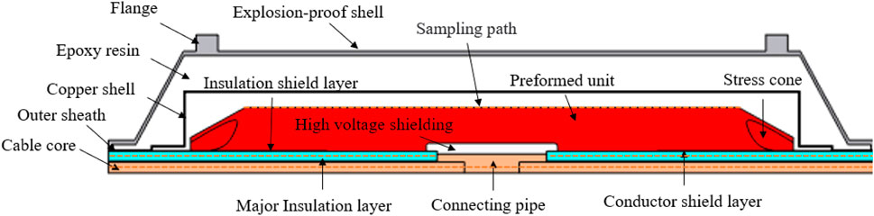
Figure 2. Physical model of high-voltage cable joint.

Table 1. Geometric structure dimensions.
2.2 Mathematical model
There are many ways for heat to be generated inside the cable, including core conductor loss, insulation dielectric loss, and metal sheath loss. Since the metal sheath loss in the cable joint is relatively small, this paper only considers the heat generation effects of the first two losses [18]. The electromagnetic-thermal coupling module is used to simulate and calculate the heat generation inside the cable joint. The form of directly applying a boundary current source is adapted to pass a stable current through the cable core and the crimping tube. Then, the temperature rise is generated through electromagnetic-thermal coupling. The thermal power at the cable core and the crimping tube can be directly calculated by the control equation without the need to calculate the equivalent area.
When a current passes through the conductor, the less power is calculated as follows Equation 1:
where P1 is the conductor loss power, I is the conductor current, and R is the conductor’s AC resistance.
Due to the existence of the skin effect of the alternating current in the conductor, the skin effect coefficient needs to be taken into account. Therefore, the conductivity is obtained as Equation 2 [19]:
where σ1 represents the conductivity of the cable core conductor, σ20 represents the conductivity of the cable core at 20°C, α represents the temperature coefficient of the copper material, and T represents the temperature of the material.
When the conductor is crimped, there is contact resistance between the crimping tube and the conductor. Therefore, considering the role of the contact resistance, the calculation of the contact conductivity is as follows Equation 3 [19]:
where σ2 is the conductivity at the crimping tube, r1 is the radius of the conductor, r2 is the radius at the crimping tube, and k is the contact coefficient.
Another major heat-generating loss is the dielectric loss of the insulation layer, which is calculated as follows Equation 4:
where P2 is the insulation loss, f is the frequency, C is the dielectric capacitance, U is the phase voltage of the dielectric to the ground, and tanδ is the dielectric loss tangent angle.
The heat transfer of high-voltage cable joints includes heat conduction, heat convection, and thermal radiation. Since there is no high-temperature heat source in the environment around the cable, the thermal radiation process can be ignored. The heat transfer of cable joints mainly involves solid-solid heat conduction and solid-fluid heat convection.
The heat transfer process inside the cable joint is heat conduction, which can be quantitatively described using Fourier’s law Equation 5 [20]:
where Φ is the heat flow in the normal direction of the heat flow, A is the cross-sectional area in the normal direction, q is the heat flux density, and λ is the thermal conductivity.
Heat convection includes natural convection and forced convection. If there is no air-cooling system in the tunnel, heat is dissipated only through natural convection, and the wind speed is generally less than 0.15 m/s [21]. To improve the heat dissipation capacity, a ventilation device will be installed in the tunnel, so that the surface of the cable joint shows the form of forced-convection heat dissipation. Heat convection is usually calculated using Newton’s law of cooling Equation 6:
where h is the surface heat transfer coefficient, and Δt is the temperature difference between the external fluid and the solid surface.
2.3 Boundary condition
For the analysis of the heat-dissipation characteristics of the cable joint studied in this paper, the setting of boundary conditions for the electric field and temperature field needs to be considered. A boundary current source is applied to one end of the cable core cross-section, and the other end of the cross-section is grounded. This can simulate a constant current in the cable core and the crimping tube. During the setting of the temperature field, since the cable joint and the explosion-proof housing are directly exposed to the air, the third-kind boundary condition is adopted. The setting is carried out with the known convective heat-transfer coefficient and fluid temperature Equation 7 [22].
where T is the surface temperature of the heat-generating body, and T0 is the ambient temperature, which is set to 20°C.
Since the two ends of the cable joint are connected to the cable body, the temperature difference between them is smaller compared to that between the heat source and the outside. Therefore, it is considered that there is no heat exchange in the axial direction between the cable joint and the cable body. Under the condition of only considering natural convective heat transfer, the radial surface in contact with the air is set as the heat flux. When considering the external ventilation condition, is achieved through the heat transfer between the solid and the fluid and the inflow and outflow of the wind direction. When studying the impact of the external air-cooling system on the heat dissipation of the joint, an air domain needs to be set outside the joint as the basis of the flow field, and the initial velocity of the fluid inflow is applied as a way to simulate the wind speed. Fluid flow is divided into laminar flow and turbulent flow. Due to the large cross-sectional area of the tunnel where the 220 kV cable project is arranged and the high Reynolds number, using turbulent flow for research is more in line with the actual situation. The fluid control equations are as follows Equation 8:
where ρ represents the air density; u represents the wind speed component in the x-direction; w represents the wind speed component in the y-axis direction; fx is the mass force of the fluid in the x-direction; p represents the absolute pressure; and μ represents the dynamic viscosity.
The temperature distribution needs to be calculated through the heat generation mode and heat exchange conditions. Therefore, the required material parameters are listed in Table 2.
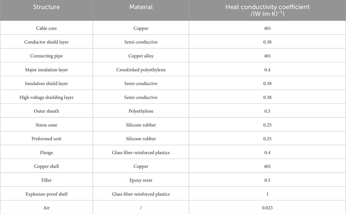
Table 2. Materials and parameters.
3 Influence of explosion-proof shell and filling material on the performance of cable joints
3.1 Influence of fillers in the explosion-proof shell on the heat dissipation characteristics of the joint
To quantitatively analyze the internal temperature distribution of the cable joint, sampling paths have been set respectively at the inner conductor of the joint, the main insulation, and the outer surface of the prefabricated component, as shown by the red straight lines in Figure 2, which is convenient for comparing the temperatures at different positions. Figures 3, 4 show the temperature fields within the explosion-proof shell of the cable joint under different fillers when a current of 1000 A is applied. The temperature distribution of the cable joint shows a pattern of gradually decreasing from the cable core and the compression joint towards the surroundings, and the lowest temperature is avoided outside the explosion-proof housing. The heat transfer coefficient of epoxy resin is much greater than that of air. Therefore, when only air is filled in the explosion-proof housing, an excessively high-temperature rise will occur, which is closer to the specified temperature of cross-linked polyethylene. Once the specified temperature is exceeded, the performance of the main insulation will drop significantly, posing a threat to the safe operation.
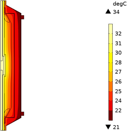
Figure 3. Temperature distribution under epoxy resin filling.
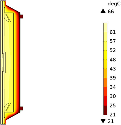
Figure 4. Temperature distribution under filled air.
Figures 5, 6 show the temperature change curves of the three sampling paths under different filling conditions. There is a significant difference in the temperature distribution when the explosion-proof shell is filled with epoxy resin and when it is filled with air. When the explosion-proof shell is filled with air, the heat cannot be dissipated outward through the explosion-proof shell promptly, resulting in heat accumulation and causing a serious temperature rise in the entire inner area of the copper housing. Under the same conditions, the temperature is, on average, nearly twice as high as that when the explosion-proof shell is filled with epoxy resin.
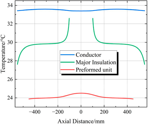
Figure 5. Temperature curves at different positions filled with epoxy resin.
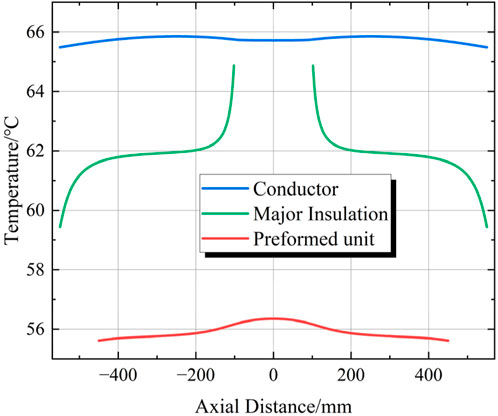
Figure 6. Temperature curves at different positions filled with air.
By comparing the sampling paths under different filling conditions, it can be seen that the cable core conductor is at a relatively high temperature, while the temperature of the outer surface of the prefabricated component is relatively low. The temperature inside the cross-linked polyethylene material of the main insulation at both ends shows a changing trend of first increasing slowly and then rising rapidly from the outside to the center along the axial direction. Since the distance between the main insulation and the copper housing at both ends of the joint is relatively small, and the heat transfer coefficient of the copper housing is relatively high, it is conducive to heat dissipation, resulting in a lower temperature at the two ends of the cable body close to the copper shell. As the sampling path gradually shifts towards the center, due to the existence of a certain contact resistance at the compression joint, the temperature on the sampling path gradually increases and reaches its peak at the center. Under normal operation, the temperature of the main insulation inside the cable joint is higher than that inside the cable body.
3.2 Analysis of the influence of different fillers and their proportions on the current-carrying capacity
Table 3 statistically analyzes the maximum temperatures at the conductor and the main insulation with two different fillers under various working conditions. As the working current gradually increases, the temperatures at the conductor and the main insulation under different fillers also increase gradually, but the increasing proportions vary.
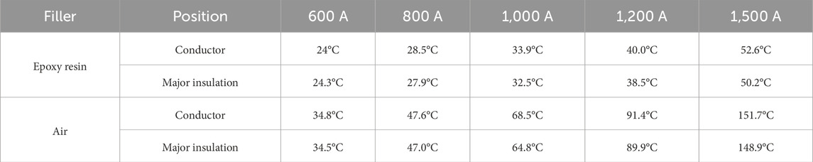
Table 3. Relationship between download traffic and maximum temperature for different fillers.
It can be seen from Figure 7 that when the explosion-proof shell is filled with epoxy resin, the temperature rises at the two positions and is relatively gentle. When the working current increases from 600 A to 1,500 A, the maximum temperature inside the conductor increases by 112%, and the maximum temperature of the main insulation increases by 106%. When the temperature reaches the specified limiting temperature of 90°C for cross-linked polyethylene [23], the maximum current-carrying capacity of the cable joint filled with epoxy resin is 2,136 A.
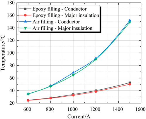
Figure 7. Current carrying capacity variation curve.
However, when the filler is air, the temperature of the conductor increases by 335%, and the temperature of the main insulation increases by 331%. At this time, the temperature far exceeds the standard temperature specified for cross-linked polyethylene, which poses a serious threat to the aging of the insulation during long-term operation. When the main insulation filled with air reaches 90°C, the maximum current-carrying capacity is 1,201 A. Therefore, when the epoxy resin filling condition is adopted, the current-carrying capacity can be increased by 1.78 times compared with that when air is used as the filler.
In the analysis of some engineering accidents, after opening the explosion-proof shell, it was found that the internal filling adhesive was not fully solidified or the amount of adhesive injection was insufficient [24]. Since the cable joint is placed horizontally in the laying pipe gallery, under the influence of gravity, the epoxy resin adhesive precipitates downward, resulting in a cavity in the explosion-proof shell of the upper half of the joint with the axis of the cable joint as the boundary, while the explosion-proof shell of the lower half of the joint is filled with epoxy resin.
This paper analyzes the influence of partially filling the epoxy resin in the explosion-proof shell of the cable joint on the heat dissipation performance of the joint by simulating the partial cavity of the explosion-proof shell under the working condition of an applied current of 1,000 A. Since the cable joint is cylindrical, to simplify the model, the proportion of the volume filled with air to the total volume inside the explosion-proof shell is taken as the independent variable, and the maximum temperature of the conductor and the maximum temperature of the main insulation are taken as the dependent variables for analysis.
It can be seen from Figure 8 that when the filler in the explosion-proof shell is not all epoxy resin, as the volume of air inside the explosion-proof shell gradually increases, the maximum temperatures of the conductor and the main insulation show a linear proportional relationship. The linear model is used for fitting, and the obtained R2 is higher than 0.99, indicating a high degree of fitting. In addition, the slopes of the two fitting lines are almost the same, and only the intercepts are different.
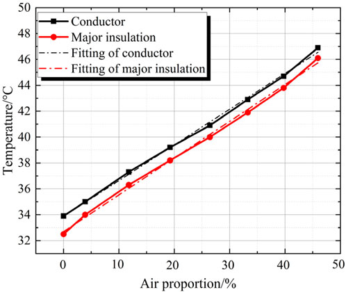
Figure 8. Temperature changes inside the joint under different air ratios.
By analyzing the characteristics of the temperature rise of the cable joint under different proportions of air volume, it is shown that the filling amount of epoxy resin in the project has a great influence on the temperature rise. When the air reaches half of the volume of the explosion-proof shell, the temperature rise of the conductor will increase by 38%, and the temperature rise of the main insulation will increase by 42%, which seriously limits the current-carrying capacity of the cable joint. Moreover, the local difficulty in heat dissipation will lead to a linear increase in temperature, which is extremely likely to cause insulation failures.
4 Analysis of Air-cooling heat dissipation of cable joints under the condition of tunnel laying
To enhance heat dissipation and increase the current-carrying capacity, when laying cables, an air-cooling system is usually installed in the tunnel. The heat dissipation performance of the cable joints is improved by converting natural convection into forced convection. However, affected by the wind speed and wind direction, sometimes the heat dissipation effect of the cable joints does not reach the best even after the air-cooling system is installed. This paper explores the influence of wind speed, wind direction, and the environment on the heat dissipation performance of cable joints by applying a single-phase flow field to the air domain around the cable joints.
4.1 Influence of wind speed on the heat dissipation characteristics of cable joints
Without external ventilation, the air velocity near cable joints in tunnel-laid conditions is generally lower than 0.15 m/s, which belongs to natural convection. The natural heat transfer coefficient under different wind speeds is usually between 1–12 W/(m2·K).
To investigate the influence of wind speed and direction on the heat dissipation characteristics of cable joints, an air domain surrounding the entire cable joint was first added outside the cable joint. Due to the low wind speed, the overall flow shows a turbulent phenomenon. Therefore, a single-phase turbulent flow field was selected in this paper and set as a low-Reynolds-number turbulent model. The fluid is in an incompressible state, which is consistent with the actual situation. Figure 9 shows the flow field distribution in the air domain under the condition of an applied wind speed of 0.5 m/s. In this paper, the wind direction is based on the axial direction of the joint. The wind direction parallel to the axial direction of the joint is the parallel wind direction, and the wind direction perpendicular to the axial direction of the joint is the vertical wind direction. The air velocity is the fastest in the middle area of the tunnel and slower near the two side walls. This is because there is friction between the air and the walls, resulting in a decrease in the flow velocity, which is in line with the actual working conditions.
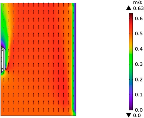
Figure 9. Distribution of air-cooled flow field in tunnel.
In addition, the structure of the explosion-proof shell has a certain influence on the wind speed. When the air impacts the flange of the explosion-proof shell, there is a small-area acceleration, resulting in a velocity higher than the initially applied speed.
This flow field is applied to the temperature field for analysis, and the results are shown in Figure 10. After the flow field is applied, the heat is further carried away from the cable joint by the wind, and the direction of heat outflow is the same as the wind direction. Under the working current of 1000A, compared with the external natural convection, the forced convection leads to a decrease in the maximum temperature by 3°C. This indicates that external ventilation can effectively reduce the internal temperature of the cable joint and enhance its heat dissipation capacity.
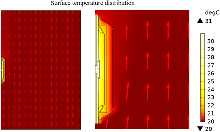
Figure 10. Distribution of joint temperature field under forced convection.
To further compare the influence of wind speed on the heat dissipation performance, fluids with speeds ranging from 0.5 to 5 m/s parallel to the cable joint are applied for comparative analysis. This segmented wind speed is below that of a Grade 3 wind, which falls within the working conditions that can be achieved by a conventional ventilation system. The temperature changes of the conductor, the major insulation, the outer surface of the preformed unit, and the outer surface of the explosion-proof shell under different wind speeds are compared, as shown in Figure 11. As the wind speed increases, the maximum temperatures at different positions all decrease, and the rate of temperature decrease gradually slows down as the wind speed increases. When the wind speed exceeds 3 m/s, the slopes of the curves of the maximum temperature change at the positions of the conductor, and the major insulation gradually decreases, and the degree of temperature decreases significantly. At this time, the temperatures drop to 91.3%, 90.9%, 96.0%, and 90.8% of the initial values respectively. Therefore, the greater the wind speed of the ventilation system, the better it can enhance the heat dissipation performance of the cable joint. However, an excessively high wind speed cannot effectively reduce the temperature. At the same time, it is also less economical to generate and maintain a high wind speed for a long time.
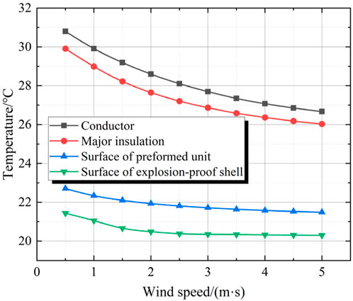
Figure 11. Influence of different wind speeds on temperature under parallel wind direction.
4.2 Analysis of the heat dissipation characteristics of cable joints under different wind directions
To further analyze the influence of the air-cooling system on the heat dissipation of cable joints, it is necessary to analyze the wind direction and explore the role of the wind direction in the heat dissipation process of cable joints. First, the parallel wind speed of 0.5 m/s under the condition of a current of 1,000 A is analyzed. By plotting and comparing the temperature curves of the conductor, the main insulation, the outer surface of the prefabricated component, and the outer surface of the explosion-proof shell, it can be seen that when the temperature is in the radial direction outward starting from the conductor, the temperature of each region gradually decreases. However, the temperature in the axial direction is no longer symmetric at both ends. In Figure 12, taking 0 as the center, the positive value of the horizontal coordinate represents the direction of the fluid inlet, and the negative value represents the direction of the fluid outlet. It can be seen that the temperatures in the four regions near the fluid inlet direction are relatively low, while the temperatures near the fluid outlet direction are higher due to heat accumulation caused by the wind direction problem.
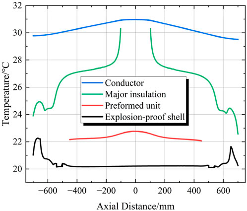
Figure 12. Temperature variation curve at different positions under parallel wind direction.
When the wind-direction angle is changed so that the fluid inlet is perpendicular to the axial direction of the cable joint, that is, the wind direction forms a 90° angle with the joint’s axial direction, the curves of the maximum temperatures at various positions under different wind speeds are plotted as shown in the following figure. It can be seen from Figure 13 that when the wind-direction angle is changed to blow perpendicularly towards the cable joint, the changing trends of the maximum-temperature curves at different positions remain the same. However, the wind speed required to reduce the maximum temperature to a constant level is significantly lower compared to the case when the wind direction is parallel to the axial direction of the cable joint. When the wind speed is 2 m/s, the temperatures have dropped to 84.4%, 85.2%, 91.3%, and 92.3% of the original values respectively. This indicates that when the wind direction is perpendicular to the axial direction of the joint, the air-cooling effect can be further enhanced, and the joint temperature can be further reduced.
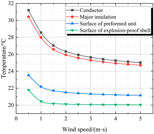
Figure 13. Influence of wind speed on temperature changes under vertical wind direction.
To analyze the specific role of air cooling in improving the current-carrying capacity of cable joints, the current-carrying capacities when the temperature at the main insulation of cable joints reaches the critical value under different wind directions and wind speeds are statistically analyzed, as shown in Figure 14. It can be seen that as the wind speed increases, the current-carrying capacities in the two ventilation directions both increase in a logarithmic function trend. When the wind speed is low, the current-carrying capacity increases rapidly. After the wind speed reaches a certain value, the increase in the current-carrying capacity is relatively gentle. Among them, the increase in the current carrying capacity under the vertical wind direction is more obvious. Under the same wind speed, the vertical wind direction has more advantages. Compared with the natural convection condition, when the external wind speed is 5 m/s, the current-carrying capacity under the vertical wind direction is increased to 150% of the original value, and that under the parallel wind direction is increased to 136% of the original value. In addition, it can be seen that when the wind speed is 0.5 m/s, the current-carrying capacity under the parallel wind direction is higher. This is because when the wind speed is low, the wind perpendicular to the axial direction of the cable joint is relatively gentle. When the heat of the joint dissipates outward, it is inhibited by the wind fluid in the opposite direction, resulting in less heat being dissipated outward. This phenomenon disappears when the wind speed is higher. Therefore, the influence of wind speed and wind direction on the heat dissipation performance of cable joints needs to be considered in the construction of the tunnel ventilation system.
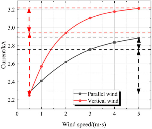
Figure 14. The degree of increase in carrying capacity by wind speed under different wind directions.
In addition, it can be observed that after the wind speed reaches a certain level, the rate of increase in the current-carrying capacity gradually decreases. This indicates that as the wind speed continuously increases, the heat exchange rate on the surface of the cable joint does not increase linearly in proportion. There is a threshold for heat dissipation. Therefore, excessively increasing the wind speed cannot further reduce the temperature of the cable joint, and maintaining an overly high wind speed incurs a relatively high economic cost. Through comparison, it can be found that when the air-cooling system has a parallel wind direction, the threshold for the increase in the current-carrying capacity appears when the wind speed reaches 3 m/s. When the wind direction is perpendicular, the threshold for the increase in the current-carrying capacity can be reached when the wind speed is 2 m/s. Therefore, in engineering, by changing the wind direction and wind speed, it is possible to achieve a greater increase in the current-carrying capacity with a relatively low wind speed.
5 Conclusion
• When the explosion-proof shell is completely filled with epoxy resin, the current carrying capacity of the joint is increased by 1.78 times compared to air. When the filling glue in the explosion-proof shell is insufficient, the temperature rise linearly increases with the increase of air proportion under the same conditions.
• The external air cooling system of cable joints can significantly reduce the temperature rise of the joints and increase the current carrying capacity. The wind direction perpendicular to the axial direction of the joint has a more significant advantage in heat dissipation compared to parallel wind direction. When the wind speed is 2 m/s, the current carrying capacity can be increased to 1.38 times that under natural convection conditions.
• When the wind direction is parallel, it is affected by the fluid thermal field, and the temperature rise in the lower air outlet area of the cable joint is higher than that in the upper air outlet area. Therefore, after running for a period of time, the air cooling should be reversed to avoid the continuous accumulation of main insulation heat.
Data availability statement
The original contributions presented in the study are included in the article/supplementary material, further inquiries can be directed to the corresponding author.
Author contributions
XY: Conceptualization, Formal Analysis, Investigation, Methodology, Writing – original draft, Writing – review and editing. ZX: Investigation, Methodology, Writing – original draft. ZK: Conceptualization, Methodology, Writing – review and editing. TF: Formal Analysis, Investigation, Methodology, Writing – original draft.
Funding
The author(s) declare that financial support was received for the research and/or publication of this article. This work is financially supported by State Grid Jiangsu Electric Power Company Limited. Technology Project (J2024053). The funder was not involved in the study design, collection, analysis, interpretation of data, the writing of this article, or the decision to submit it for publication.
Conflict of interest
Authors XY, ZX, ZK, and TF were employed by State Grid Jiangsu Electric Power Co., Ltd.
Generative AI statement
The author(s) declare that no Generative AI was used in the creation of this manuscript.
Publisher’s note
All claims expressed in this article are solely those of the authors and do not necessarily represent those of their affiliated organizations, or those of the publisher, the editors and the reviewers. Any product that may be evaluated in this article, or claim that may be made by its manufacturer, is not guaranteed or endorsed by the publisher.
References
1. Yang F, Cheng P, Luo H, Yang Y, Liu H, Kang K. 3-D thermal analysis and contact resistance evaluation of power cable joint. Appl Therm Eng (2016) 93:1183–92. doi:10.1016/j.applthermaleng.2015.10.076
2. Chou W, Cui J, Huang S, Liu Z, Yang X, Zhong Q, et al. Optimum design of the front part structure of explosion-proof device for high-voltage cable joints based on multi-physics couplin. Electrotechnical Appl (2019) 38(04):86–92.
3. Lin S, Hu W. Theoretical research on temperature field of power cable joint with FEM. In: 2012 international conference on system science and engineering (ICSSE). IEEE (2012). p. 564–7.
4. Henke A, Frei S. Analytical thermal cable model for bundles of identical single wire cables. IEEE Trans Power Deliv (2023) 38(5):3107–16. doi:10.1109/tpwrd.2023.3272837
5. Wu L, Jin Q, Yu X, Zhang B. Electromagnetic-thermal multi-physics coupling simulation of cable joints: considering contact resistance and typical defects. Front Energy Res (2024) 12:1475355. doi:10.3389/fenrg.2024.1475355
6. Xu Z, Qian J. Comparison of different methods for calculating electrical parameters of power cables. High Voltage Engineerin (2013) 39(03):689–97. doi:10.3969/j.issn.1003-6520.2013.03.027
7. Yu J, Chen X, Zhou H. Electric field calculation and optimization for stress cone of DC cable joint based on the coaxial double-layer insulation model. IEEE Trans Dielectrics Electr Insul (2020) 27(1):33–41. doi:10.1109/tdei.2019.008284
8. Ruan JJ, Liu C, Huang DC, Zhan QH, Tang LZ. Hot spot temperature inversion for the single-core power cable joint. Appl Therm Eng (2016) 104:146–52. doi:10.1016/j.applthermaleng.2016.05.008
9. International Electrotechnical Commission. (2006). IEC60287-1 Calculation of the currentrating-part l: current rating equation(100% load factor) and calculation of losses. Geneva, Switzerland: IEC.
10. International Electrotechnical Commission. (1994). IEC60853-1 Calculation of the cyclic and emergency current rating of cables-part 1: cyclic rating factor for cables up to and including 18/30(36kV). Geneva, Switzerland: IEC.
11. Chen J, Li C, Tao F, Liu J, Tan X, Hu L, et al. Study on temperature field simulation of three-core cable joint with installation of fire-proof and explosion-proof box. High Voltage Apparatus (2024) 60(11):123–30. doi:10.13296/j.1001-1609.hva.2024.11.015
12. Sedaghat Ali, Leon D. Thermal analysis of power cables in free air: evaluation and improvement of the IEC standard ampacity calculations. IEEE Trans Power Deliv (2014) 29(5):2306–14.
13. Ren H, Zhong L, Yang X, Li W, Gao J, Yu Q, et al. Electric field distribution based on radial nonuniform conductivity in HVDC XLPE cable insulation. IEEE Trans Dielectrics Electr Insul (2020) 27(1):121–7. doi:10.1109/tdei.2019.008345
14. Bhatti AA, Yang B, Peng X, Xia Z, Dong L, Wang H, et al. Simulation of temperature distribution behavior of high voltage cable joints with typical defects. In: 2021 6th asia conference on power and electrical engineering. ACPEE IEEE (2021). p. 1139–43.
15. Wei Y, Liu M, Li X, Li G, Li N, Hao C, et al. Effect of temperature on electric-thermal properties of semi-conductive shielding layer and insulation layer for high-voltage cable. High Voltage (2021) 6(5):805–12. doi:10.1049/hve2.12089
16. Cho J, Kim JH, Lee HJ, Kim JY, Song IK, Choi JH. Development and improvement of an intelligent cable monitoring system for underground distribution networks using distributed temperature sensing. Energies (2014) 7(2):1076–94. doi:10.3390/en7021076
17. Xia C, Liu H, Wu G, Xia Z. Research on heat dispersion and ampacity of three-core cable joints with explosion-proof box. Electr Measurement&Instrumentation (2022) 59(09):47–52. doi:10.19753/j.issn1001-1390.2022.09.007
18. Zhang Z, Deng X, Liang L, Wang X, Chen Y, Ruan J. Temperature field calculation and thermal circuit equivalent analysis of 110 kV core cable joint. Processes (2024) 12(3):463. doi:10.3390/pr12030463
19. Li C, Yang W, Cai Y, Li B, Xin Y, Yang J. An electromagnetic-thermal modeling method for the joint resistance of the CORC cable. IEEE Trans Appl Superconductivity (2023) 34(5):1–5. doi:10.1109/tasc.2023.3343687
20. Pu L, Duan W, Sun J, Zhao X, Xiong L. Core temperature calculation of single-core cable joints based on FEM. Power Syst Clean Energy (2021) 37(02):57–63.
21. Bragatto T, Cresta M, Gatta FM, Geri A, Maccioni M, Paulucci M. Assessing thermal behavior of medium voltage cable joints through simulations and measurements. IEEE Trans Industry Appl (2023) 59(5):5705–14. doi:10.1109/tia.2023.3284413
22. Xiao J, Zhang J, Bao S, Shan L, Su J, Xu Y, et al. Heat dissipation measures of high voltage cable joint with protective box. Guangdong Electric Power (2021) 34(07):120–6. doi:10.3969/j.issn.1007-290X.2021.007.014
23. Liu Y, Wang H, Zhang H, Du B. Thermal aging evaluation of XLPE power cable by using multidimensional characteristic analysis of leakage current. Polymers (2022) 14(15):3147. doi:10.3390/polym14153147
Keywords: high voltage cables, cable connectors, explosion proof shell, tempe rature distribution, current carrying capacity
Citation: Yong X, Xin Z, Ke Z and Feiyue T (2025) Investigation on temperature characteristics of high voltage cable joints. Front. Phys. 13:1584225. doi: 10.3389/fphy.2025.1584225
Received: 27 February 2025; Accepted: 26 March 2025;
Published: 09 April 2025.
Edited by:
Feng Bin, Changsha University of Science and Technology, ChinaReviewed by:
Jingmin Fan, Guangdong University of Technology, ChinaHongshun Liu, Shandong University, China
Copyright © 2025 Yong, Xin, Ke and Feiyue. This is an open-access article distributed under the terms of the Creative Commons Attribution License (CC BY). The use, distribution or reproduction in other forums is permitted, provided the original author(s) and the copyright owner(s) are credited and that the original publication in this journal is cited, in accordance with accepted academic practice. No use, distribution or reproduction is permitted which does not comply with these terms.
*Correspondence: Xu Yong, NTc2MTIzMzAwQHFxLmNvbQ==