 Jiawei He
 Shaojie Ni1,2
- 1College of Electronic Science and Technology, National University of Defense Technology, Changsha, China
- 2National Key Laboratory for Positioning, Navigation and Timing Technology, Changsha, China
Positioning, Navigation, and Timing (PNT) services are essential for supporting various aspects of modern society. Fields such as communications, transportation, and military operations heavily rely on accurate and reliable PNT services, with this dependence expected to grow. However, the limitations of the predominant Global Navigation Satellite System (GNSS) in complex environments have become increasingly apparent. As an effective supplementary approach, space-based signals of opportunity (SOPs) from Low Earth Orbit (LEO) have garnered significant attention. This paper begins by introducing the principle of Doppler location and analyzing its error sources. It then discusses in detail the methods of observation extraction, including cognitive-based and blind-based methods. Focusing on major domestic and international LEO constellations (such as Iridium, Orbcomm, Globalstar, Starlink, OneWeb, etc.), this paper summarizes their signal characteristics and the current status of positioning research, and discusses the latest advancements in observable estimation algorithms. Finally, the paper proposes key research directions for the future, including breakthroughs in satellite recognition technology, optimization of positioning algorithms, development of multi-source fusion positioning technology, and observation extraction in complex environments.
1 Introduction
Since the advent of the Global Navigation Satellite System (GNSS), it has played a pivotal role in both military and civilian domains, making irreplaceable contributions to national defense and economic construction. As its application scope continues to expand, the demands on GNSS have far exceeded the initial design specifications. The most prominent issue is the inability of traditional satellite navigation receivers to meet positioning requirements in complex environments [1]. Firstly, the signal strength of satellite signals diminishes with increasing propagation distance during space transmission, resulting in weak signal power reaching the ground and limiting its application in urban areas and canyons. Secondly, GNSS operates on a single, transparent frequency point, making it vulnerable to malicious interference and deception, which can lead to service unavailability. The limitations of Global Navigation Satellite Systems have been significantly exacerbated in recent battlefield scenarios observed during the Russia-Ukraine conflict, where such systems have demonstrated critical vulnerabilities and operational unreliability in combat environments. In stark contrast, LEO satellite constellations exemplified by Starlink have emerged as resilient alternatives. These advanced LEO systems not only maintain robust communication capabilities but also demonstrate enhanced positioning potential in complex battlefield conditions, presenting a paradigm shift in tactical navigation solutions. Over the past decade, an increasing number of researchers have demonstrated the potential of signals of Opportunity (SOPs) in Positioning, Navigation, and Timing (PNT), which can effectively compensate for the shortcomings of GNSS.
SOPs positioning technology offers a viable alternative for positioning services when GNSS signals are unavailable or denied. SOPs encompass all potential radio signals in the environment from which location and time information can be extracted for navigation purposes. These signals are categorized into land-based and space-based SOPs. Ground-based SOPs, such as radio, mobile communication, and WIFI signals, primarily cover urban areas but lack coverage in deserts, oceans, and remote regions. In contrast, space-based SOPs utilize Earth-orbiting satellites as radiation sources, including non-cooperative/non-navigation satellite signals, non-cooperative navigation satellite signals, and cooperative non-navigation signals. Compared to ground-based SOPs, space-based signals offer the advantage of extensive coverage, enabling seamless global positioning. Among these, Low Earth Orbit (LEO) satellite signals are a typical example of space-based SOPs emitters. Compared with GNSS satellites in Medium Earth Orbit (MEO), LEO satellites exhibit significant advantages, such as rapid geometric changes, stronger received signal strength, and larger Doppler frequency shifts [2]. Additionally, many LEO constellations possess rich spectral resources and strong anti-interference capabilities. Moreover, Two-Line Element (TLE) data for LEO satellites is readily available, allowing for precise satellite position calculations through models like the Simplified General Perturbations No. 4 (SGP4). These advantageous properties ensure the PNT capabilities of LEO satellites in GNSS-denied environments. Consequently, LEO constellations are considered a promising alternative for PNT services. Currently, numerous countries are planning or have already launched a large number of LEO satellites, providing abundant radiation sources for space-based SOPs [2–4]. Table 1 lists the main LEO satellite constellations that have been deployed or are planned both domestically and internationally.
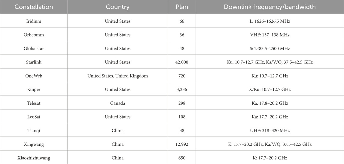
Table 1. Major domestic and international LEO constellations.
The first satellite navigation system was the U.S. Navy’s Meridian Satellite Navigation System (TRANSIT), which was the first positioning system based on satellite Doppler. It was introduced for military applications in 1964 and then disclosed for positioning and navigation services in 1968. The TRANSIT system used the Doppler frequency shift of LEO satellite signals to achieve a positioning accuracy of about 70 m [5, 6]. This system demonstrated the method of using LEO satellites for positioning within the framework of SOPs navigation. The advantages of opportunistic LEO positioning technology are evident [7]:
1. A large number of satellites can provide signals globally, making opportunistic LEO satellites a potential global PNT system.
2. Almost no additional infrastructure is required, and positioning can be achieved using existing receivers.
3. The satellite system does not need to be adjusted, and it can be used without special navigation functions for LEO satellites.
4. User-side positioning can be realized, and the user’s location will not be disclosed to constellation operators, thus protecting user privacy.
Despite the many advantages of opportunistic LEO positioning technology, it also faces several challenges. Most of these challenges stem from the fact that satellite systems or transmitted signals are not designed for PNT purposes. This leads to two main issues [8]:
1. Non-navigation signals may lack broadband pseudo-random codes for satellite identification and pseudo-range measurement. The modulation format of the signal is unknown or partially unknown, making it difficult to extract navigation observations from satellite signals.
2. Weak space-time reference: Most LEO satellites are not equipped with high-precision atomic clocks like those in traditional GNSS systems. Therefore, they lack precise clocks, making it difficult to meet the requirements for high-precision pseudo-range measurement. Additionally, there is a lack of strict clock synchronization between satellites, and most broadcast ephemeris data are not available. The published TLE data and the Simplified General Perturbations No. 4 (SGP4) model can be used, but this introduces significant system errors into the positioning algorithm.
The solutions to these problems will be described in the main part of the article.
Given the challenges associated with space-based LEO signals of opportunity, this paper reviews the development process of space-based SOPs positioning, focusing on the extraction of mesoscopic measurements and the correction of systematic errors. We first describe the principle of Doppler positioning. Then, we analyze the Doppler positioning performance and main error sources of LEO satellites, summarize the existing LEO-based navigation systems, their observation extraction methods, and determine the future research direction in this field.
2 Doppler positioning
2.1 Positioning principle
Benefiting from the rapid movement of LEO satellites, there is a significant difference in relative motion speeds between satellites and the ground, resulting in an obvious Doppler effect. Therefore, LEO satellites generally use Doppler frequency shift information for positioning, typically employing integrated Doppler and instantaneous Doppler as observation measurements [9, 10]. Generally, the integrated Doppler measurement value is used as the navigation observation value and then converted into a range difference bi-curve. Through the accumulation of measurements at multiple different times, the intersection of multiple hyperboloids determines the position. When there are many visible satellites, instantaneous Doppler positioning, i.e., single epoch positioning, can be used. Generally, at least four satellites are required for instantaneous Doppler positioning, and instantaneous Doppler measurement information can be used to achieve real-time positioning.
The Doppler frequency is a function of satellite speed and position, which can be obtained through auxiliary information. According to the satellite’s velocity and position, and the measured Doppler shift, a circular conical surface with equal Doppler can be determined. For static receivers, since the receiver’s coordinates remain constant over time, Doppler measurements from the same or different satellites at different times can be used for positioning. When a user receives a satellite signal, the Doppler shift value of the signal can be measured, and the user must be on the equivalent Doppler circular conical surface (EDCCS) with the satellite as the apex. The Doppler shift value is the same for all points on this surface and equals the measured Doppler shift value. When signals from multiple satellites are received, multiple equivalent Doppler circular conical surfaces are formed. These surfaces intersect at a point, which is calculated as the user’s position. Figure 1 illustrates the principle of Doppler positioning.
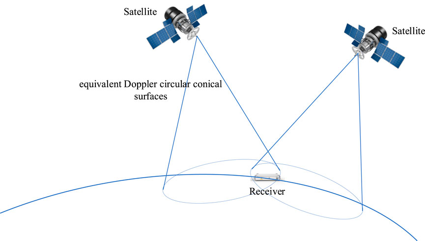
Figure 1. Schematic diagram of Doppler positioning.
2.2 Measurement equation
The Doppler effect, caused by the relative motion between the satellite signal transmitter and the ground receiver, can be expressed as:
In the Equation 1,
In the Equation 2,
In the Equation 3,
In the Equation 4,
In the Equation 6,
2.3 Location model
In traditional GNSS pseud-orange positioning, an initial estimate is typically provided to the user, and the Newton iteration method is employed for iterative calculation. The final convergence value is utilized as the positioning result. Doppler-based positioning systems generally utilize two models. One is a positioning model based on the least squares method, and the other is a positioning model based on the extended Kalman filter. In the currently published literature, the least squares method is suitable for static receivers, while the extended Kalman filter (EKF) is suitable for both static and dynamic receivers. Both methods require an initial estimated solution
In the Equations 7, 8,
In the Equation 9,
In the Equation 10,
The positioning models based on the least squares method are not robust to erroneous data, but they are simple and offer high computational efficiency [31]. Psiaki et al. [33] demonstrated single epoch positioning simulations using the Doppler frequency shift from eight or more measurements through least squares fitting. Khalife et al. [34] employed the weighted least squares method to achieve multi-epoch positioning using the Doppler frequency shift of Starlink satellites. For positioning models based on the extended Kalman filter (EKF), in addition to utilizing the aforementioned linearized observation model, the state model of the receiver is also required. The accuracy of the state model directly impacts the positioning performance of the receiver. Singh et al. [35] introduced the use of the EKF to fuse information from multiple satellites for positioning and evaluated the algorithm’s performance. In addition to the initial state, an initial error covariance matrix must be provided when using the EKF. Currently, there is no explanation in the published literature on how to determine the initial covariance matrix. Beyond its application in positioning models, the EKF is also frequently used in observation extraction. Stock et al. [7] summarized examples of EKF usage in existing literature and explained its feasibility with the navigation system.
3 Error source analysis
The measurement errors can be categorized into three types based on their sources: satellite-related errors, signal propagation-related errors, and receiver-related errors. Satellite-related errors primarily consist of satellite clock errors and satellite ephemeris errors. These errors are caused by the inability of the satellite ground monitoring system to make absolutely accurate measurements and predictions of the satellite orbit and the frequency drift of the satellite clock. Signal propagation-related errors refer to the atmospheric delay caused by the impact of satellite signals as they pass through the atmosphere. Receiver-related errors are caused by the multipath effect and the clock error of the receiver. The following sections analyze the impacts on Doppler-based positioning in LEO systems and present corresponding mitigation strategies. Table 2 provides a fundamental overview of error sources and their associated mitigation techniques, with generalized indications of each error source’s relative significance. However, when considering specific opportunistic LEO-PNT implementations, the actual relevance of these error sources may diverge substantially from the tabular representations. This discrepancy arises because error source impacts are fundamentally contingent upon multiple system-specific parameters including (but not limited to) constellation size, signal frequency allocation, observation duration characteristics, and orbital data provenance.
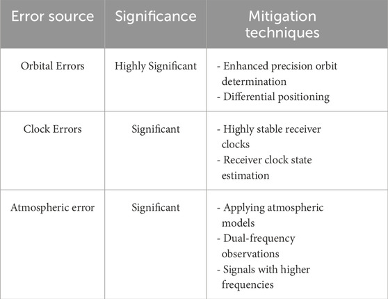
Table 2. Major error sources in opportunistic LEO-PNT.
3.1 Satellite orbit error
The rapid movement of LEO satellites results in frequent changes in their position and elevation, making LEO-based positioning more sensitive to satellite-related errors, such as satellite position and velocity errors. The orbit determination of GNSS satellites has been extensively studied, achieving accuracy at the centimeter level or higher. However, for LEO satellites without GNSS receivers and atomic clocks, this poses a challenging problem [12]. A precise Positioning, Navigation, and Timing (PNT) receiver needs to know the position and velocity of the satellite at the time of signal transmission. Typically, this information is obtained using a set of parameter data called ephemeris, such as the TLE file format published online by Celestrak [13]. TLE files are published once or twice a day, including the status of satellites at specific past times, and then the SGP4 propagation algorithm is used to predict the satellite’s position and velocity during signal transmission [14, 15]. Since the estimated orbit observation data and model contain errors, and the orbit recurrence method also introduces errors, the assumed satellite state of the receiver differs from the actual state, resulting in positioning errors of the receiver.
The accuracy of satellite orbits has always been a focal point for space-based signals of opportunity (SOP). Currently, the only available online resource is the Two-Line Element (TLE) file released by the North American Aerospace Defense Command (NORAD). However, the accuracy of these orbits at the epoch time is approximately 3 km [16], and the accuracy is further reduced due to the recurrence of orbits. In this context, satellite orbit error is typically considered the primary error source for space-based SOP positioning. Qinhonglei et al. [17] used a geometric analysis method to analyze the impact of orbit error on Doppler positioning error from a geometric perspective. For a stationary ground receiver, the relative operating speed between the transmitter and the receiver is primarily caused by the satellite’s speed, which can be expressed as:
In the Equation 11,
When an error exists in the satellite speed, the field-of-view angle will change accordingly. This relationship can be expressed as:
In the Equation 12,
The impact of velocity error on positioning is shown in Figure 2A. The effect of satellite velocity error on the equivalent Doppler circular conical surface is to alter the field-of-view angle. When the receiver uses this satellite and other satellites for positioning, due to the presence of satellite velocity error, the actual intersection should be located on the inaccurate equivalent Doppler circular conical surface, rather than the true equivalent Doppler circular conical surface. Consequently, the positioning solution is at point B rather than the true position A. In reality,
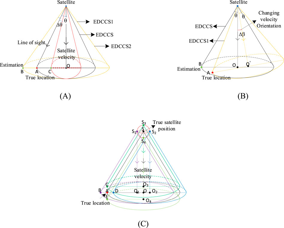
Figure 2. Impact analysis of orbital errors [16]. (A) Velocity errors (B) velocity direction errors (C) Position errors.
When considering the influence of satellite motion direction error, let
For the satellite position error, the field angle of the equivalent Doppler conical surface is independent of the satellite’s position. The impact of this error on positioning is depicted in Figure 2C. The satellite position with error is located inside or on the surface of a sphere centered at the true satellite position, with a radius equal to the maximum error
Therefore, the satellite position error transforms the normal equivalent Doppler circular conical surface into an irregular geometry. Generally, the sensitivity of Doppler positioning to satellite position error is less than that to satellite velocity error. This is because the former only changes the position of the equivalent Doppler circular conical surface, while the latter changes the field angle, and the positioning error is related to the line of sight. For a specific satellite, the influence of orbit error on the equivalent Doppler circular conical surface is the combination of all effects of satellite positioning error, satellite velocity error, and velocity direction error. When the orbit error exists, the satellite velocity error will change the contour of the equivalent Doppler circular conical surface, while the satellite position error will change the position of the equivalent Doppler circular conical surface, resulting in an irregular geometry of the equivalent Doppler circular conical surface.
Shi et al. [10] conducted a simulation analysis by adding random errors of varying magnitudes to the satellite position or velocity. The results indicate that the positioning results are less sensitive to satellite position errors than to satellite velocity errors. The positioning accuracy will be reduced if the satellite position error is at the meter level and the velocity error is at the centimeter level per second. When the satellite orbit error increases by one order of magnitude, the positioning error will also increase by one order of magnitude. The positioning results are presented in Table 3, where RMS, N, E, and U represent the root mean square, north, east, and up directions, respectively.
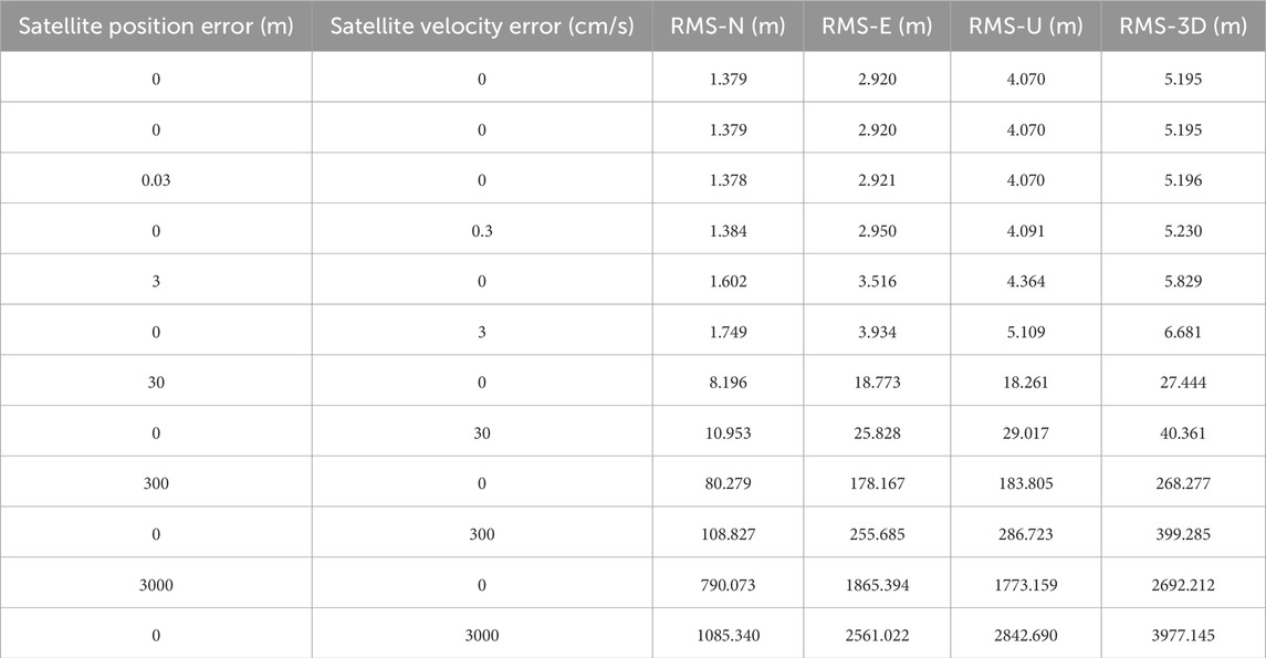
Table 3. Impact of different orbital errors on Doppler positioning accuracy [9].
In order to address the impact of satellite orbit errors, Ardito et al. [18] proposed a Simultaneous Tracking and Navigation (STAN) framework, which solves this issue by tightly integrating an Inertial Navigation System (INS) with Doppler and pseudo-range measurements. Khalife et al. [19] proposed a differential framework to tackle this problem. Qinhonglei et al. [20] targeted the traditional long baseline model, arguing that the assumption of parallel sight vectors between the two receivers in the basic differential positioning model is untenable. They proposed a Doppler differential positioning algorithm based on sight vector correction. By determining the sight vectors, the projection of the baseline in this direction becomes a pseudorange difference, thereby reducing positioning errors under long baselines. Zhao et al. [21] analyzed the error elimination method in the differential Doppler positioning system based on the differential framework and proposed a signal transmission time algorithm based on Maximum Likelihood Estimation (MLE) to mitigate the impact of orbit errors. In addition to the differential method requiring additional reference stations, Wang et al. [22] reduced the impact of satellite position errors by introducing a coarse time compensation term. Although this compensates for errors along the satellite motion direction, it cannot compensate for radial direction errors. Furthermore, positioning accuracy can also be improved by obtaining high-precision tracking data. Khairallah and Kassas et al. [16] conducted experiments on Doppler and carrier phase ephemeris tracking, providing precise ephemeris for positioning another static receiver. To address the challenge that traditional orbit determination methods are difficult to apply to non-cooperative LEO satellites, Deng et al. [23] proposed a multi-receiver Doppler orbit determination scheme and introduced a Search Least Squares (SLS) algorithm for initial orbit determination, offering a reliable initial value method for accurate orbit determination. However, this method is overly dependent on prior orbit parameters. With the advancement of artificial intelligence, machine learning methods are gradually being applied to the orbit determination of LEO satellites.
3.2 Clock error
Because most LEO satellites are not designed for navigation purposes, the on-board clock of LEO satellites is not necessarily an atomic clock, nor is it necessarily precisely synchronized. In addition, the receiver typically uses a lower-quality oscillator. Therefore, the offset and drift of the satellite and receiver clocks may be quite significant. Although LEO opportunistic signal positioning is not affected by the clock offset between the satellite and the receiver as in the pseudorange positioning of the GNSS system, the clock drift between the satellite and the receiver will seriously impact the measured Doppler frequency shift.
Mortlock et al. [24] conducted a simulation-based comparative analysis through two controlled experimental scenarios:1. Fixed receiver clock with variable satellite clock parameters; 2. Fixed satellite clock with variable receiver clock specifications. Their investigation systematically quantified how positioning performance responds to receiver clock quality variations and transmitter clock imperfections in LEO constellations. Notably, the study revealed that positioning accuracy exhibits remarkable insensitivity to LEO transmitter clock quality regardless of constellation size. In a complementary approach, Cassel et al. [25] implemented synchronized clock variation simulations where both transmitters and receivers employed identical clock architectures. Their results demonstrated that simultaneous adoption of next-generation atomic clocks at both ends enhances Doppler-based positioning precision by approximately an order of magnitude compared to conventional oscillators. These findings collectively establish that receiver clock characteristics exert critical influence on LEO-PNT performance–while transmitter clock quality shows limited impact, receiver clock advancements yield substantial system-level improvements.
To mitigate the impact of clock errors, several methods have been proposed. Wang et al. [26] addressed the impact of receiver clock errors on LEO positioning performance by proposing a mutual feedback positioning algorithm based on the LSTM model and the error state Kalman filter (ESKF) model, which can compensate for clock errors and reduce their impact on positioning accuracy. To enhance the accuracy of the receiver clock model, Cassel et al. [25] utilized a more complex three-state model instead of the conventional dual-state model, thereby improving positioning accuracy. In addition to reducing the impact of receiver clock errors, this approach can also enhance the accuracy of LEO clocks. Yang et al. [27] proposed a real-time estimation method for low Earth orbit (LEO) satellite clock errors based on ground tracking stations, and the feasibility of this method was verified through simulations. Wang et al. [28] investigated two typical types of satellite clocks and proposed a LEO satellite clock prediction model based on GNSS accurate clock estimation. The model considered systematic effects and was compared with a simple polynomial fitting model. Khairallah et al. [29] proposed a method for adaptive estimation of satellite clock state noise covariance for positioning filtering. Compared with the Kalman filter with mismatched measurement covariance, this method can improve positioning accuracy.
3.3 Atmospheric error
Atmospheric errors can be categorized into ionospheric and tropospheric errors. Ionospheric delay is inversely proportional to the square of the frequency and directly proportional to the total number of free electrons in the signal path. Small-scale irregularities in electron density lead to rapid fluctuations in amplitude (fading) and carrier phase (scintillation). Due to the group delay effect of the ionosphere, pseudo-range and phase measurements deviate, and since frequency is the rate of phase change over time, Doppler measurements are also affected. The impact of ionospheric delay on positioning accuracy is highly dependent on the signal frequency. For Doppler-based positioning systems, the ionospheric effect is primarily reflected in the change of delay rate. The ionospheric delay rate for VHF/L-band signals cannot be ignored in LEO positioning, as it is inversely proportional to the square of the frequency. In the VHF band, ionospheric delay rate can cause positioning errors based on Doppler frequency shift of up to several kilometers [30]; in the L-band, the error is tens of meters [10]; in the K-band, the error is far less than 1 m and can be neglected [10]. For dual-frequency receivers, ionospheric delay rate can be eliminated by using ionosphere-free combinations of pseudo-range rate measurements. However, this method is not suitable for space-based LEO opportunistic signals. Nonetheless, the ionospheric effect can be mitigated by using signals with higher carrier frequencies.
In addition to the ionospheric effect, the tropospheric effect must also be considered. Since the troposphere is non-dispersive, it introduces a non-frequency-selective delay to the signal, which depends on factors such as temperature, atmospheric pressure, humidity, water vapor, and elevation [31]. Similar to the ionosphere, the troposphere also introduces a delay rate. For Doppler positioning, a high delay rate may lead to Doppler positioning errors as large as tens of meters [10]. If the tropospheric error is not corrected, the positioning accuracy will deteriorate significantly. Tropospheric error can be corrected through modeling. Khalife et al. [32] studied the impact of tropospheric delay on carrier phase and differential measurements using the typical Hopfield model and concluded that the longer the baseline length, the greater the residual delay, and the greater the impact on positioning accuracy.
4 Advances in observable extraction and positioning using LEO opportunistic signals
At present, the number of LEO satellites in orbit is the largest, and tens of thousands of LEO satellites will be launched in the next few years, providing a large number of radiation sources for space-based signals of opportunity positioning. In recent years, low Earth orbit satellite systems (such as Orbcomm, Starlink, OneWeb, etc.) have developed rapidly. Many scholars regard them as signals of opportunity sources to study and explore the possibility of their positioning. Table 4 summarizes the information of the five LEO constellations that have been widely studied at present. In this paper, the LEO constellations in the following table will be introduced in detail, and their current research status will be summarized.
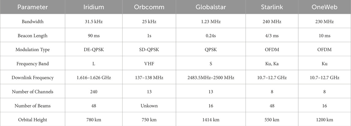
Table 4. Comparison of LEO constellation parameters.
4.1 Location based on iridium opportunistic signal
The Iridium system, proposed by Motorola, is a global satellite mobile communication system. It comprises 66 LEO satellites, distributed across 6 orbital planes, with each plane consisting of 11 operational satellites and 1 backup satellite. The orbital inclination is 86.4°, and the altitude is approximately 780 km, enabling global coverage. After undergoing bankruptcy and reorganization, the system was redesigned as the second-generation Iridium Next to provide Satellite Timing and Location (STL) services. These services are intended to serve as a backup to the Global Positioning System (GPS) and represent a dedicated low Earth orbit positioning system. Iridium Next employs Time Division Multiple Access (TDMA) for signal transmission. The downlink frequency band allocated to Iridium is 1616–1626.5 MHz, of which 1616–1626 MHz are duplex channels used as traffic channels, divided into 30 sub-bands. Each sub-band is further divided into 8 channels, resulting in a bandwidth of 41.67 kHz per channel. The 1626–1626.5 MHz band is a simplex channel, divided into 12 subchannels, each with a bandwidth of 41.67 kHz. This bandwidth is further divided into a working bandwidth of 31.50 kHz and a protection bandwidth of 10.17 kHz [36]. Five simplex downlink channels are utilized, including Ring Alert signal and four other signals. The Medium Quaternary Message Channel is also used for the Satellite Time and Location service, which is only accessible to authorized users. The remaining seven simplex downlink channels serve as protection bands [37]. The downlink frequency band distribution of the system is illustrated in Figure 3.
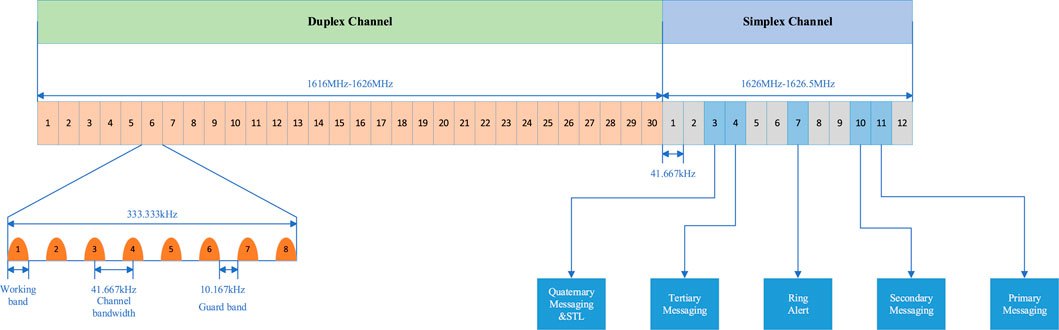
Figure 3. Iridium system user link frequency band allocation [43].
The frame length of Iridium Next is 90 ms, and the Ring Alert signal has high availability and wide coverage, which meets the requirements for positioning. Users can receive the Ring Alert signal in simplex channel 7 every 4.32 s, with a time slot length of 20.32 ms for the simplex channel. Each Ring Alert signal consists of three parts: an unmodulated single-tone signal; a unique word modulated using Binary Phase Shift Keying (BPSK), whose modulation information is a 12-bit baseband data represented as “789” in hexadecimal; and data information modulated using Differential Quadrature Phase Shift Keying (DQPSK) [38]. The structure of the Iridium Next burst signal is shown in Figure 4. The single-tone signal is located at the front of the signal with a duration of 2.6 ms; the unique word has a duration of 0.48 ms; the data information is located at the end of the signal and has a duration of 3.42–17.24 ms [39], depending on the duration of the transmitted data. The duration of the Iridium Next signal ranges from 6.5 ms to 20.32 ms, with most signals lasting approximately 7 ms, and its spectrum is shown in Figure 5.
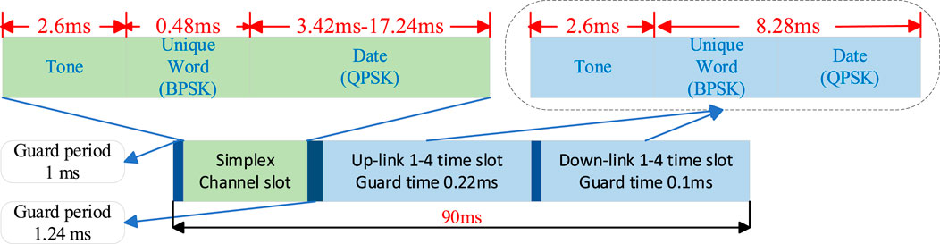
Figure 4. Iridium next burst signal structure.
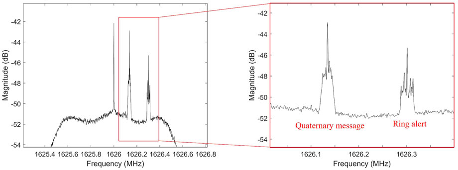
Figure 5. Power spectrum of Iridium-next [67].
The Iridium Next signal is a discontinuous signal with a burst structure. Currently, most methods for its localization are based on the burst signal. A clear single-tone signal is transmitted at the front of each burst signal to facilitate signal acquisition, enabling the estimation of the Doppler frequency shift. The traditional Doppler measurement method for Iridium Next signals is typically implemented in the frequency domain. Khalife et al. [40] proposed a method that involves raising the signal to the Mth power to eliminate the influence of modulation information, then performing a Fast Fourier Transform (FFT) on the Mth power signal, and searching for the FFT peak as the Doppler measurement value to obtain the Doppler frequency shift of Iridium Next. Based on the unique structure of the Iridium Next signal, the existing Doppler measurement methods can be summarized as follows: first, coarse Doppler estimation is obtained by FFT for the single-tone (pilot) signal in the burst signal. Then, precise Doppler measurement is achieved through frequency-domain maximum likelihood estimation [17, 41]. Although the frequency-domain Doppler measurement algorithm is effective and relatively simple, its performance is limited by the frequency resolution. The traditional time-domain Doppler measurement method is generated by carrier phase difference. However, since the Iridium Next signal is modulated by QPSK and the modulation information is unknown, it is difficult to estimate the carrier phase, and this method is affected by noise in baseband signal processing. Wei et al. [42] proposed a method of fitting the phase of explicit and implicit pilots to obtain Doppler measurements. This method is limited to the simulation phase and is only applicable to signals with known implicit pilots. For signals without known implicit pilots, this method cannot further improve Doppler accuracy. Huang et al. [39] proposed the phase time method, which can utilize the complete Iridium Next signal, including pilot and modulation signals, without requiring prior information. This method can obtain more accurate Doppler measurements in static receivers and improve the stability and reliability of positioning, but it lacks verification in dynamic scenarios. To address the localization accuracy limitations of the Doppler-based method, Liang et al. [43] proposed a localization method based on Doppler-compensated pseudorange by decoding the Iridium signal. This method obtains the pseudorange and pseudorange rate by jointly estimating the time delay and Doppler, and uses this information for positioning. This method solves the problem of inconsistency between the epoch time of the Iridium signal and the assumed signal time. By estimating the epoch time error and compensating the pseudorange, the positioning error is significantly reduced. However, this method has the issue of high complexity and difficulty in adapting to rapidly changing signal environments. Tan et al. [44] studied the positioning method using Iridium signals in weak signal environments, analyzed the signal characteristics of Iridium in detail, and proposed a QSA-IDE algorithm to estimate its Doppler frequency shift in weak signal environments. This novel approach enhances weak-signal Doppler estimation through two-stage processing:1. Quadratic square accumulation processing boosts signal-to-noise ratio (SNR); 2. Full-duration Iridium signals are utilized for maximum likelihood estimation (MLE) to achieve precise Doppler frequency shift estimation.
4.2 Location based on Orbcomm opportunistic signals
The Orbcomm system is a two-way communication system that utilizes a low Earth orbit satellite constellation to provide global geographic coverage. There are 42 satellites distributed across 7 orbital planes labeled a through g [45]. Each of the a, b, c, and d planes contains 8 satellites, with an inclination of 45° and an orbital altitude of approximately 815 km. Plane e has an inclination of 0°, includes 6 satellites, and has an orbital altitude of 975 km. Plane f has an inclination of 70° and contains two satellites in a near-polar circular orbit at an altitude of 740 km. Plane g has an inclination of 108° and contains two satellites in a near-polar elliptical orbit, with the orbital altitude varying from 785 km to 875 km. Orbcomm completed the deployment of the second-generation satellite (OG2) constellation in 2014. The OG2 constellation is a Walker constellation, with its satellites evenly distributed across four orbital planes at an inclination of 47°. The orbital altitude and period of the OG2 satellite are approximately 710 km and 97 min, respectively. Currently, positioning research based on the Orbcomm satellite is conducted using the OG2 satellite.
The Orbcomm system employs Frequency Division Multiple Access (FDMA) to transmit downlink signals, which occupy the Very High Frequency (VHF) band of 137–138 MHz, as illustrated in Figure 6 [46].
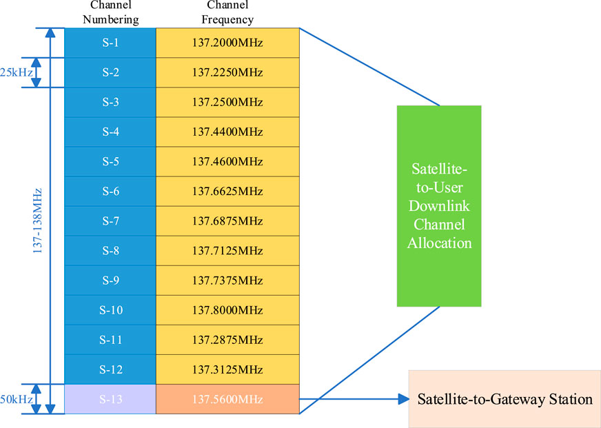
Figure 6. Orbcomm satellite downlink frequency band allocation [46].
The downlink channel of the Orbcomm system includes 12 channels designated for user transmission and one gateway channel for ground station transmission. Each satellite broadcasts signals in two specific channels through spectrum sharing, employing symmetric differential quadrature phase shift keying (SD-QPSK) modulation, with a symbol rate of 4,800 bps. Currently, only the VHF signal of the downlink channel is utilized for opportunistic localization.
The expression of SD-QPSK modulation signal is:
In the Equation 13,
In the Equation 14,
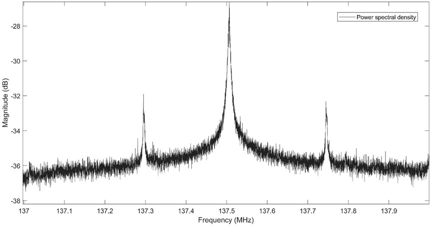
Figure 7. Power spectrum of Orbcomm [67].
The power of the Orbcomm satellite signal reaching the ground is generally higher than that of the noise. Due to its SD-QPSK modulation, it is unable to directly obtain the Doppler measurement value through its spectrum. When using the Maximum Likelihood Estimation (MLE) method for accurate Doppler measurement, the correlation between the local carrier generated by the Doppler rough measurement value and the Orbcomm signal affects the relevant peak, which is influenced by the data bits. Qinhonglei et al. [46] found that after square processing of their signals, peak spectral lines appeared symmetrically on the left and right sides of the center frequency of the signal spectrum. Zhao et al. [41] detected the Orbcomm signal according to the spectral characteristics and estimated the coarse Doppler by calculating the center frequency of the bispectral line. Khalife et al. [47] used a phase-locked loop to achieve positioning of the Orbcomm opportunity signal and employed a Costas loop based on the maximum likelihood phase discriminator. However, the symbol period limits the coherent integration time, which reduces the input signal-to-noise ratio of the ML phase detector and makes the ML Costas loop unstable. Xie et al. [48] designed a carrier tracking loop based on square sum code phase assistance, which eliminates the disadvantage of the symbol period limiting the coherent integration time and obtains accurate carrier phase measurement under a low carrier-to-noise ratio.
4.3 Location based on Globalstar opportunistic signals
The Globalstar second-generation constellation, operational since 2013, consists of 32 satellites distributed in 8 orbital planes (4 satellites per plane) at an altitude of 1,414 km. This system employs Wideband Code Division Multiple Access (WCDMA) technology with QPSK modulation for its communication signals, as specified in. The user link facilitates bidirectional ground-to-satellite communication through a transparent payload architecture: user terminals receive signals relayed from ground stations via satellites, defined as the forward link. Specifically, the downlink operates in the S-band at 2,483.5–2,500 MHz, which constitutes the forward link’s frequency allocation. To date, all published studies exclusively utilize the forward link’s pilot signal for positioning purposes, whose modulation structure (including chip rate, symbol mapping, and pseudorandom noise sequence design) is analytically illustrated in Figure 8.
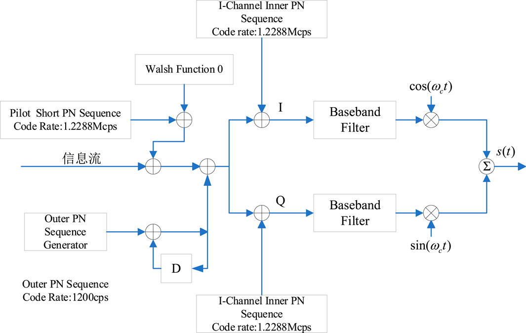
Figure 8. Forward link QPSK spread spectrum modulation.
Each pilot signal employs three distinct pseudo-random noise (PN) sequences for QPSK modulation, namely, the short PN sequence, inner PN sequence, and outer PN sequence. These sequences are used to distinguish between satellites, orbits, and beams. In summary, the Globalstar downlink pilot signal can be expressed as:
In the Equation 15,
Doppler compensation is the most challenging issue in opportunistic positioning using Globalstar satellites. In the Globalstar system, Doppler is compensated to a nominal value at the satellite or ground station [49]. When Doppler compensation is applied, the Doppler measured by the ground receiver differs from the true Doppler, making the measured Doppler unsuitable for opportunistic localization. Neinavaie et al. [50] confirmed the presence of Doppler compensation through experiments and found discrepancies between the received Doppler and theoretical calculations. They proposed a method to recover the Doppler frequency by exploiting spectral distortion, enabling the retrieval of the true Doppler frequency even when compensation is applied. Zhang et al. [51] analyzed the modulation process of Globalstar signals, processed the Quadrature Phase Shift Keying (QPSK) pilot signal to the fourth power, selected an appropriate Fast Fourier Transform (FFT) time, extracted the Doppler observation value, and discovered that the pilot signal of the Globalstar forward link in Beijing did not pre-compensate for Doppler. Due to the low signal-to-noise ratio of the Globalstar signal, traditional quartic despreading severely degrades the signal-to-noise ratio, leading to the failure of Doppler frequency extraction. Qinhonglei et al. [52] proposed that the acquisition of the Globalstar pilot signal is achieved by decoding the square cross-harmonic term and conducting parallel code phase frequency searches. The decoded local spread spectrum sequence is not affected by the degradation of the signal-to-noise ratio, thereby overcoming the challenge of low signal-to-noise ratio to a certain extent.
4.4 Location based on Starlink opportunistic signals
Starlink, a low Earth orbit (LEO) satellite constellation launched by SpaceX, aims to provide high-speed Internet services globally [53]. The system comprises thousands of satellites operating at different altitudes, with the majority located in LEO at an altitude of 550 km. To date, over 7,000 satellites have been launched, with 4,748 currently in service, primarily distributed across five distinct orbital shells to achieve global coverage. The detailed format of Starlink’s downlink signals is not publicly available. The only known information about these signals is their carrier frequency and bandwidth. The downlink signals occupy a 250 MHz bandwidth in the Ku band to provide high-speed broadband connections. Nine single-tone signals are broadcast at the center of this bandwidth, spaced approximately 43.9 kHz apart [4].
Neinavaie et al. [54] analyzed the spectrum of the received Starlink signal after Doppler compensation and found that, in addition to the central single-tone signal, the Starlink downlink signal spectrum contains subcarriers similar to those used in Orthogonal Frequency Division Multiplexing (OFDM), as shown in Figure 9. Humphreys et al. provided a blind identification technology for the downlink signal of the satellite link in the 10.7–12.7 GHz band, given its OFDM format. This technology is an extension of the existing blind orthogonal frequency division multiplexing signal recognition method [55]. Using this method, the structure of the Starlink downlink signal in the 10.7–12.7 GHz band is described in detail, and the parameters within the signal are estimated and identified, as shown in Table 5. Currently, the published literature indicates that Starlink is primarily used to extract observations by utilizing its beacon signals located at the center of the user’s downlink signal channel, i.e., a single-tone signal or by assuming that there is a periodic reference sequence in the frame of the OFDM signal.
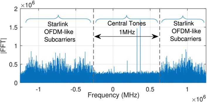
Figure 9. Spectrum of Starlink downlink signals after Doppler rate wipe-off [54].
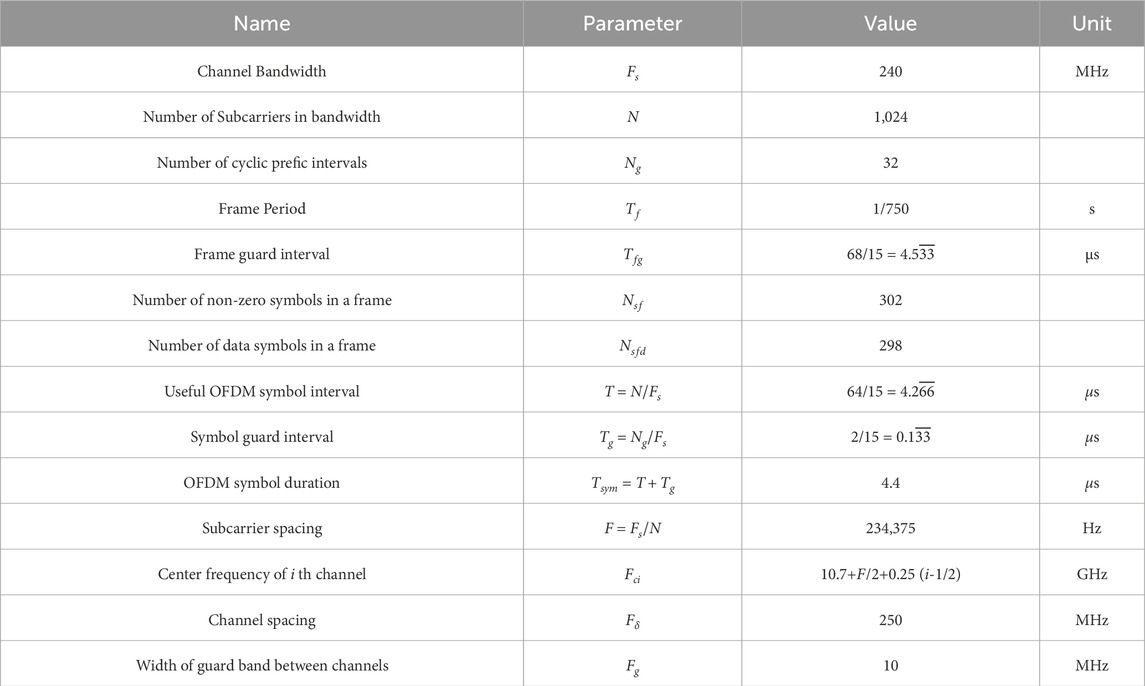
Table 5. Starlink downlink signal parameters [55].
For the single-tone signal in the spectrum, Khalife et al. [56] observed the beacon signal at 11.325 GHz of the Starlink satellite and used a carrier phase tracking algorithm based on the Adaptive Kalman filter to extract the Doppler frequency shift, achieving a three-dimensional positioning error of 33.5 m and a horizontal positioning error of 25.9 m. Jardak et al. [57] explored the feasibility of receiving Starlink downlink signals for positioning without using a parabolic reflector and proposed a signal detection and tracking method using a general low noise block down converter and software-defined radio, which aggregated the Doppler frequency shift of multiple subcarriers of the beacon signal, reducing the impact of measurement noise. Yang et al. [58] proposed a baseband signal processing scheme without prior information of receiver position and time. Through a two-step method, it is challenging to determine the signal source of the Starlink signal in the presence of multiple satellites, and simple single-tone tracking cannot accurately estimate the carrier center frequency, which introduces ambiguity to Doppler estimation. Nonetheless, this method realizes the effective utilization of the Starlink signal and accurate Doppler and Doppler rate estimation. Qinhonglei et al. [59] used the beacon signals located at 11.325 GHz and 11.575 GHz simultaneously for positioning, employed the short-time Fourier transform for coarse Doppler extraction, and then used maximum likelihood estimation for accurate measurement. With the aid of elevation data, the horizontal positioning error of the results was 15 m. Yuanyiping et al. [60] designed a lightweight modular universal receiving device and observed the beacon signal (11.95 GHz/12.45 GHz) at the interval center between the downlink signal channels of the satellite link for the first time. Based on the beacon signal, a frequency-domain sliding window estimation algorithm was proposed, which successfully realized the estimation of Doppler frequency shift.
In addition to utilizing existing beacon signals, some scholars assume that the downlink signals of satellite link users contain periodic reference signals and use the characteristics of these periodic signals to extract the Doppler frequency shift. Khalife et al. [61] hypothesized that the downlink signal of the satellite link user contains periodic reference signals. Based on this assumption, they constructed a matching subspace detection method to detect the unknown reference signal of Starlink and estimate the unknown period and Doppler frequency. They also proposed a linear frequency modulation parameter estimator to track the Doppler frequency of the unknown Starlink signal by using the Wigner distribution to estimate the parameters of the linear frequency modulation signal. Building on this, the team developed an algorithm based on the Kalman filter to track the Doppler frequency of the unknown Starlink signal [34]. Neinavaie et al. [54] combined the beacon-based method with the OFDM-based reference signal method to significantly reduce the positioning error, decreasing the horizontal positioning error from 10 m to 6.5 m and thereby improving positioning accuracy. Shadram et al. [62] proposed a sequential method based on the classical linear model to estimate the number of Starlink satellites and their corresponding reference signals. This method uses the generalized likelihood ratio detector to design the Doppler tracking algorithm, establishes the equivalence between the generalized linear model and the matched subspace detector for the first time, and employs differential Doppler positioning technology to simultaneously receive satellite link beacon signals through two receivers separated by 1 km. The horizontal positioning error of the result is 5.6 m. Kozhaya et al. [63] proposed a blind Doppler spectrum method from the perspective of the frequency domain. This method uses a blind Doppler discriminator based on the frequency domain and a Doppler tracking algorithm based on the Kalman filter to achieve Doppler tracking accuracy at the Hertz level and a 2-D positioning error of 4.3 m.
4.5 Location based on OneWeb opportunistic signals
One of the goals of the OneWeb constellation is to create a navigation system independent of the Galileo system. The constellation plans to have 720 satellites, distributed across 18 orbital planes, with an orbital altitude of approximately 1,200 km and an orbital inclination of 87.9°. Satellites are evenly distributed within each plane and travel along the north-south direction. Satellites in adjacent planes are offset by half a satellite in latitude. OneWeb users’ downlink signals are transmitted in the Ku band (10.7–12.7 GHz), and the downlink band is divided into eight consecutive 250 MHz channels [64]. The OneWeb constellation typically provides users with one of the 16 downlink beams at any given time, and each beam transmits on only one of the eight channels. Therefore, each OneWeb satellite multiplexes multiple users through frequency division (8 × 250 MHz channels) and spatial division (16 beams), as illustrated in Figure 10.
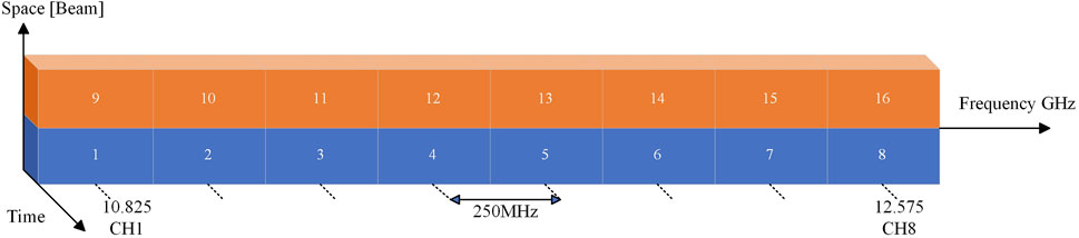
Figure 10. Diagram showing OneWeb’s Ku-band downlink signal allocation [65].
At present, the public literature indicates that research on positioning using the OneWeb constellation is limited. Kozhaya et al. [65] conducted the first study on OneWeb LEO satellite signals. Given the acquisition challenges such as high Doppler frequency and large search grid, they proposed a Doppler search algorithm based on two-step sampling to reduce computational complexity. A Kalman filter tracking loop combined with a phase-locked loop and delay locked loop was utilized to track satellite signals, generate code phase and carrier phase observations, and achieve positioning based on nine OneWeb satellites. Additionally, no other literature on OneWeb constellation positioning has been found.
4.6 Observation estimation algorithm
Before opportunistic low Earth orbit (LEO) positioning, navigation, and timing (PNT) processing, observations must be estimated as accurately as possible. However, the acquisition and frequency estimation of LEO signals are very challenging. Firstly, due to the high and rapidly changing relative speed between the transmitter and receiver, the transmission channel imposes a significant Doppler frequency shift on the signal. In addition, if the exact signal structure is not known, signal acquisition and frequency estimation will be hindered, requiring more complex algorithms. While the aforementioned challenges pose significant difficulties in observable extraction, thereby adversely affecting positioning accuracy. The current positioning results derived from major constellations have yielded surprisingly encouraging outcomes. A comparative analysis of these results is presented in Table 6, as detailed below. As illustrated in the table, opportunistic signals typically rely on either Doppler frequency shift measurements or carrier phase observations as primary observables. Currently, the published signal acquisition and observation estimation algorithms can be divided into two categories: one is a cognitive-based method, which uses the least available prior information about the LEO satellite signal structure; the other is the blind method, which does not assume that the Doppler frequency, modulation type, length, and symbol of the beacon signal are known, but only knows its bandwidth, and uses a cognitive decoding method to obtain this information [66].
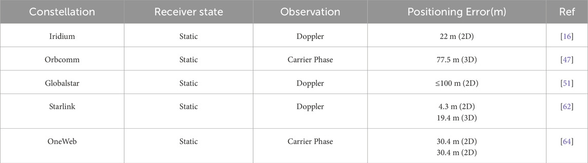
Table 6. Comparative analysis of positioning performance across satellite constellations.
4.6.1 Cognitive based approach
These methodologies typically necessitate prior knowledge of the satellite signal architecture, including modulation schemes, timing characteristics, and protocol-specific features, to enable effective observable extraction and parameter estimation.
4.6.1.1 Mth-power algorithm
The Mth-power algorithm is specifically designed for M-ary Phase Shift Keying (MPSK) modulated satellite signals. This method operates by raising the received signal to the Mth power to eliminate modulation symbol effects, followed by spectral analysis via Fast Fourier Transform (FFT). In reference [47], it is deduced that the carrier phase or Doppler frequency shift of multiple different carrier frequency multiplexed signals is used. An independent Phase-Locked Loop (PLL) is employed to track the LEO satellite signal of each channel, and a maximum likelihood phase discriminator is used to obtain the phase error. Reference [40] proposed a receiver architecture suitable for processing Time Division Multiple Access (TDMA) and Frequency Division Multiple Access (FDMA) signals from Orbcomm and Iridium next-generation satellites. The received signals are down-converted and partitioned to generate Doppler frequency measurements of multi-constellation LEO satellites. However, when processing TDMA signals, it is necessary to use an energy detector to obtain the burst start time during its initialization phase and assume that the initial Doppler frequency is known. Reference [67] designed a multi-constellation software-defined receiver capable of processing QPSK modulated signals from Orbcomm and Iridium next satellites. The received signals are processed to the fourth power, the power spectral density (PSD) is analyzed using the Welch method, the PSD peak is found through a search window to determine the Doppler frequency, and the Doppler frequency shift of the detected signals is tracked using the classic Costas loop. Literature [41, 68] proposed a Doppler fusion positioning model based on the Helmert variance component estimation (HVCE) algorithm, analyzing the above Doppler frequency shift extraction methods of Orbcomm and Iridium signals, which improved positioning accuracy.
4.6.1.2 Code phase search acquisition algorithm
The Code Phase Search Acquisition Algorithm can be employed to extract Doppler observables from opportunistic signals. Its fundamental principle lies in extracting the PN code sequences utilized in LEO satellite pilot signals or exploiting known pilot sequences, followed by correlation processing with the intermediate frequency signals acquired by receivers to estimate observation parameters. As demonstrated in literature [51], this methodology has been successfully applied to extract Doppler observables from GlobalStar downlink pilot signals, achieving horizontal positioning accuracy better than 100 m. The implementation procedure involves: Firstly, obtaining squared cross-harmonic terms through squaring processing. Owing to the strict orthogonality between the quadrature-phase and in-phase PN code sequences embedded in pilot signals, their coupled sequences maintain orthogonal characteristics while preserving identical code period and chip rate as the original PN sequences [51]. This inherent property facilitates periodic superposition operations, thereby enabling effective estimation of spread spectrum codes. Reference [69] studies the problem of joint synchronization and positioning using signals with known pulse shapes and modulation schemes and proposes a bandwidth-efficient algorithm for estimating the time difference of arrival (TDOA) and frequency difference (FDOA) between two receivers without exchanging original signals. Reference [71] proposed a Doppler frequency shift estimation algorithm based on correlation, but this algorithm assumes that the synchronization sequence is known.
4.6.1.3 Matched subspace detector
The matched subspace algorithm constitutes a Doppler observable extraction methodology rooted in binary hypothesis testing and maximum likelihood estimation principles. The matched subspace detector has been widely used to address the detection problem of signal sources with unknown parameters in the presence of other interference sources [72, 73]. In the Starlink satellite, there are always-on and on-demand OFDM signals [70]. Certain LEO satellite synchronization signals exhibit inherent periodicity in their transmission characteristics, as exemplified by the Starlink constellation’s synchronization signal architecture. In OFDM-based transmission, each OFDM frame contains periodic signals that are always-on and on-demand, which are used for synchronization and channel estimation. The period of these signals is typically equal to the frame length of the OFDM signals. However, in most cases, the synchronization sequence and its length are unknown. References [34, 61, 62] utilize the matched subspace algorithm to detect received opportunistic signals to provide initial estimates of unknown parameters. These parameters include: 1. The unknown number of satellites, 2. The corresponding periodic signal, and 3. Linear frequency modulation parameters (Doppler and Doppler rate). This method detects satellite signals in the environment by solving hypothesis testing problems at different stages. Compared with reference [90], a constant Doppler subspace is used to distinguish different satellites, and the matched subspace is defined based on the LFM parameters of each satellite. At each stage, a hypothesis test is conducted to detect the strongest satellite signal, and the LFM subspace of the previously detected satellite periodic signal is set to zero. A generalized likelihood ratio detector is used in each stage of the sequential detection algorithm. In the first stage of the sequential algorithm, it detects whether there is the strongest satellite signal. If the null hypothesis is accepted, it means that no satellite signal is detected in the received signal. If the null hypothesis is rejected, it indicates that there is at least one satellite signal, and if the detected satellite signal exists, hypothesis testing is carried out to detect the presence of other satellite signals, and the unknown LFM parameters and periodic sequence of each satellite signal are estimated at each stage.
4.6.2 Blind based approach
The core capability of a blind receiver lies in its ability to cognitively decode partially transmitted signals, estimate and track them, and ultimately generate navigation observables.
4.6.2.1 Blind beacon estimation algorithm
This algorithm postulates the existence of periodically transmitted beacon signals and performs blind estimation through coherent integration of subsequent signal transmissions. The methodology proves applicable during online navigation operations or pre-navigation calibration phases, enabling subsequent utilization in formal navigation processes. As beacon signals become a priori known (or estimated) during navigation phases, such receiver architectures typically achieve concurrent estimation of carrier phase, Doppler shift, and code phase parameters through adaptive tracking loops. Currently, most communication systems incorporate periodic reference signals, which can thus be leveraged for opportunistic navigation [74, 75]. Reference [76] proposed a blind opportunistic navigation (BON) framework, which can decode and utilize signals of opportunity for navigation without fully understanding the prior knowledge of the signals. The framework primarily comprises three key steps: blind Doppler frequency estimation, coherent integration, and beacon signal decoding. The blind Doppler frequency estimation algorithm is employed to estimate the Doppler frequency of the opportunity signal, thereby mitigating the impact of high dynamic effects on the coherent integration time. Building on this foundation, reference [77] introduced a blind channel equalization step to compensate for channel distortion, focusing on the blind detection and tracking of M-PSK modulated signals. A chirp parameter estimation algorithm based on the Wigner distribution was proposed to estimate and track the time-varying Doppler frequency, achieving long-term coherent integration of the signal and enhancing the signal-to-noise ratio. Drawing on the aforementioned two articles, reference [78] presented a navigation framework with high computational efficiency, concentrating on the detection of constrained unknown beacon signals. Low-complexity beacon detection and blind Doppler frequency shift estimation algorithms were proposed, addressing detection challenges under conditions of unknown beacon signals and low SNR. Literatures [79–81] concentrate on extracting navigation information from orthogonal frequency division multiplexing (OFDM) signals with unknown signal structures. Particularly for OFDM signals transmitted by low Earth orbit (LEO) satellites, the importance of blind signal processing at the receiver end is emphasized. That is, without knowledge of the specific signal structure, navigation information within the signal is detected, tracked, and utilized through cognitive decoding techniques. Reference [79] proposed a computationally efficient blind Doppler frequency estimation algorithm and discussed solving the ambiguity problem in Doppler estimation using polynomial curve fitting. Reference [80] also proposed a blind Doppler estimation algorithm, focusing more on reducing the impact of Doppler frequency through preprocessing and employing a difference framework to resolve the ambiguity problem in Doppler estimation, thereby obtaining more accurate navigation observations. The aforementioned algorithms are all designed for a single signal source. Literature [81] proposed a receiver architecture for signal detection and tracking in both static and high dynamic Doppler rate scenarios, capable of jointly estimating the unknown reference signals of multiple signal sources. This architecture can detect and track the “always-on” and “on-demand” signals of 5G NR and Starlink satellites. Reference [82] do not assume any specific modulation scheme but only assume the presence of a periodic reference signal in the received signal and proposed a general receiver architecture, highligh ting the versatility and adaptability of the receiver to different signals.
4.6.2.2 Frequency-domain estimation methodology
This approach initiates analysis through spectral decomposition of received signals, leveraging distinctive spectral signatures to construct optimized estimator configurations. References [83, 84] both employ blind Doppler discriminators based on spectral cross-correlation and Kalman filter (KF) for Doppler tracking. However, literature [83] focuses on the design of a three-stage blind receiver, while literature [84] focuses on the estimation framework of blind periodic sequences, estimating LEO satellite repeat sequences without knowledge of the signal structure and proposing a solution to the ambiguity of Doppler estimation. As demonstrated in literature [59], spectral analysis of Starlink beacon signals revealed three critical subcarrier characteristics: (1) an approximate linear correlation between spectral bandwidth and integration time, (2) constant signal power characteristics, and (3) individual subcarriers exhibiting frequency-modulated (FM) signal behavior. This fundamental insight enables the transformation of Doppler extraction challenges into parameter estimation problems for short-duration linear frequency-modulated (LFM) signals. Based on this framework, the authors developed a frequency-domain sliding-window estimation algorithm that successfully achieved Doppler shift estimation through adaptive spectral tracking and phase continuity maintenance across consecutive window intervals.
In observable extraction, cognitive-based and blind-based approaches leverage the characteristics of opportunistic signals in the time and frequency domains, respectively. Table 7 summarizes the advantages and disadvantages of these algorithms. Cognitive-based methods are more suitable for scenarios with known signal structures, such as commercial satellites, offering high accuracy but limited flexibility. In contrast, blind-based approaches are ideal for unknown or dynamic signals, like emerging LEO constellations, providing robustness but requiring solutions for ambiguity and computational complexity issues.
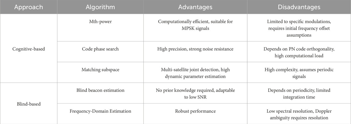
Table 7. Comparison of different extraction methods.
5 Future research directions
The preceding research has demonstrated that LEO opportunistic positioning can function effectively in GNSS-denied environments. However, most of these achievements have been realized through data post-processing, which is still far from practical application. In addition to the error sources that impact the opportunistic positioning system, there are still several issues that require further investigation to facilitate the eventual application of the opportunistic positioning system. The following section summarizes the key issues that warrant further exploration.
5.1 Satellite identification
The receiver in both GNSS systems and opportunistic positioning systems must know the satellite’s position and velocity of the transmitted signal, which is essential for the receiver to achieve positioning. It is relatively easy for GNSS systems to obtain such information, but it is challenging for opportunistic positioning systems. For existing opportunistic signal receivers, it is common to track a specific satellite and receive signals from only one satellite at a time. In practical positioning tasks, the opportunistic receiver often does not know which satellite the received signal is from. It must match the observed signal with one of the thousands of candidate satellites to identify and obtain its orbital information. This can be achieved by searching for the most matching satellite from all possible satellite ephemerides using the measured Doppler curve and the receiver’s prior position information [58]. However, when the receiver’s prior position information is unavailable or the satellite orbits are very close, this method may fail. Therefore, it is urgent to find a new technology that allows the receiver to recognize satellites through satellite signals.
5.2 Optimization of location algorithm
For receivers in both GNSS and opportunistic positioning systems, receiver initialization is required when performing a positioning solution, meaning an initial solution must be provided. In GNSS positioning, each coordinate component of the receiver’s initial position can be simply set to zero. By using the Newton iteration method, a convergent solution can be obtained within just a few iteration cycles. In Doppler-based LEO positioning, an appropriate initial value must be given. When using a least squares-based positioning solution, the epoch solution will fail if the initial value error exceeds 200 km [10]. In the Extended Kalman Filter (EKF) method, a larger error in the initial iteration value will lead to a larger velocity error [85]. In low dynamic scenarios, this issue can be resolved by introducing a Tikhonov regularization term [86]. However, this method fails in high dynamic scenarios. Therefore, it is of great significance to study the sensitivity of initial values in LEO Doppler positioning and to obtain accurate initial values without relying on additional prior information.
5.3 Multi source fusion location
For positioning in GNSS-denied environments, multi-sensor data fusion can compensate for PNT services by utilizing other navigation sources when GNSS is unavailable. Currently, the multi-source fusion of LEO opportunistic signals includes: multi-constellation fusion [84], fusion with inertial navigation systems [87], or fusion with altimeters [88]. Additionally, fusion with other sensors, such as LiDAR or ground-based opportunistic PNT, may also be beneficial [82]. In general, sensor fusion enhances the positioning accuracy and availability of opportunistic systems by incorporating additional information. Although multi-source fusion offers numerous advantages, the complexity of the receiver increases due to the fusion processing of multi-source data. Moreover, under multi-source fusion, each data source is interconnected and influences the others. If one of them is erroneous, it will also impact the final positioning result. Therefore, it is necessary to study localization algorithms with low complexity and various fusion strategies that can identify and eliminate abnormal data, leveraging the benefits of multi-source data.
5.4 Observation extraction in complex environment
At present, most of the published experiments on low Earth orbit (LEO) opportunistic positioning are conducted in simple scenarios, where there is an absence of obstructions from surrounding buildings or trees. The received signals in these experiments typically have a high signal-to-noise ratio (SNR) and are less affected by multipath effects. To date, only a limited number of studies have specifically considered signals with low SNR in complex environments [44, 57, 89]. Low-cost or small antennas are unable to provide significant antenna gain, and interference and occlusion in complex environments further reduce the SNR of the signals. A low SNR makes signal detection more challenging, leading to difficulties in observation extraction and reducing the accuracy and availability of the estimated observations. Therefore, it is urgent to investigate observation extraction methods in complex environments, with a focus on the performance of observable signal estimation algorithms.
6 Conclusion
This paper reviews the current state, key technologies, and future research directions in positioning using terrestrial low-orbit opportunistic signals. As the limitations of Global Navigation Satellite Systems (GNSS) in complex environments become increasingly evident, terrestrial low-orbit opportunistic signal positioning has emerged as a promising complementary approach. We delve into the principles of Doppler positioning, analyze error sources, and explore observable extraction methods while summarizing major technological advancements to date. The accuracy and reliability of observable extraction are critical to positioning performance. Existing methods are introduced and compared, and challenges in positioning algorithms—such as sensitivity to initial values and the complexity of multi-source data fusion—are highlighted. Cognitive-based methods rely on prior signal knowledge, while blind approaches offer greater adaptability; both face accuracy challenges from multipath effects and low signal-to-noise ratios in complex environments.
Future development in terrestrial low-orbit opportunistic signal positioning is likely to focus on several key areas: 1) Advancing satellite recognition technology and developing efficient signal feature extraction and matching algorithms; 2) Refining positioning algorithms to create robust methods that minimize dependence on prior information; 3) Promoting multi-source fusion positioning technology to enhance accuracy and availability; 4) Designing signal processing algorithms for complex environments to improve the availability and reliability of observables.
In conclusion, terrestrial low-orbit opportunistic signal positioning holds significant potential. However, breakthroughs are still needed in observable extraction, algorithm optimization, multi-source fusion, and adaptability to complex environments. These advancements will pave the way for practical applications and provide reliable PNT services in GNSS-denied environments.
Author contributions
JH: Writing – original draft, Writing – review and editing. SN: Methodology, Writing – original draft, Writing – review and editing. HL: Methodology, Writing – original draft, Writing – review and editing. ZL: Writing – original draft, Writing – review and editing, Supervision. ZX: Conceptualization, Investigation, Methodology, Supervision, Writing – original draft, Writing – review and editing.
Funding
The author(s) declare that financial support was received for the research and/or publication of this article. National Natural Science Foundation of China under Grant U20A0193.
Conflict of interest
The authors declare that the research was conducted in the absence of any commercial or financial relationships that could be construed as a potential conflict of interest.
Correction note
A correction has been made to this article. Details can be found at: 10.3389/fphy.2025.1653131.
Generative AI statement
The author(s) declare that no Generative AI was used in the creation of this manuscript.
Publisher’s note
All claims expressed in this article are solely those of the authors and do not necessarily represent those of their affiliated organizations, or those of the publisher, the editors and the reviewers. Any product that may be evaluated in this article, or claim that may be made by its manufacturer, is not guaranteed or endorsed by the publisher.
References
1. Li X, Lu Z, Yuan M, Liu W, Wang F, Yu Y, et al. Tradeoff of code estimation error rate and terminal gain in SCER attack. IEEE Trans Instrumentation Meas (2024) 73:1–12. doi:10.1109/TIM.2024.3406807
2. Reid TG, Neish AM, Walter T, Enge PK. Broadband LEO constellations for navigation. NAVIGATION: J Inst Navigation (2018) 65(2):205–20. doi:10.1002/navi.234
3. Reid TG, Neish AM, Walter TF, Enge PK. Leveraging commercial broadband leo constellations for navigating. In: 29th international technical meeting of the satellite division of the institute of navigation (ion Gnss+ 2016), 12 (2016). p. 2016–6. doi:10.33012/2016.14729
4. Del PI, Cameron BG, Crawley EF. A technical comparison of three low earth orbit satellite constellation systems to provide global broadband. Acta astronautica (2019) 159:123–35. doi:10.1016/j.actaastro.2019.03.040
5. Danchik RJL. Lee pryor the navy navigation satellite system (transit) (1984). Available online at: https://secwww.jhuapl.edu/techdigest/Content/techdigest/pdf/V05-N04/05-04-Danchik.pdf (Accessed February 15, 2025).
7. Stock W, Schwarz RT, Hofmann CA, Knopp A. Survey on opportunistic PNT with signals from LEO communication satellites. IEEE Commun Surv and Tutorials (2024) 30:77–107. doi:10.1109/COMST.2024.3406990
8. Kassas Z, Neinavaie M, Khalife J, Khairallah N, Kozhaya S, Haidar-Ahmad J, et al. Enter LEO on the GNSS stage. Inside GNSS (2021)(6):16.
9. Benzerrouk H, Nguyen Q, Xiaoxing F, Rasaee H, Landry RJ. LEO satellites based Doppler positioning using distributed nonlinear estimation. IFAC-PapersOnLine (2019) 52(12):496–501. doi:10.1016/j.ifacol.2019.11.292
10. Shi C, Zhang Y, Li Z. Revisiting Doppler positioning performance with LEO satellites. GPS Solutions (2023) 27(3):126. doi:10.1007/s10291-023-01466-w
11. Li ZH, Huang JS. GPS measurement and data processing. 3rd Edition. Wuhan: Wuhan University Press (2016).
12. Morales JJ, Khalife J, Cruz US, Kassas ZM. Orbit modeling for simultaneous tracking and navigation using LEO satellite signals. In: InProceedings of the 32nd international technical meeting of the satellite division of the institute of navigation (ION GNSS+ 2019) (2019). p. 2090–9. doi:10.33012/2019.17029
13. CelesTrak. Two-line element sets (2023). Available online at: http://celestrak.org/publications (Accessed July 25, 2023).
14. Vallado D, Crawford P, Hujsak R, Kelso TS. Revisiting spacetrack report# 3. In: AIAA/AAS astrodynamics specialist conference and exhibit. (2006). p 6753. doi:10.2514/6.2006-6753
15. Vallado D, Crawford P. SGP4 orbit determination. In: InAIAA/AAS astrodynamics specialist conference and exhibit (2008). p. 6770. doi:10.2514/6.2008-6770
16. Khairallah N, Kassas ZM. Ephemeris closed-loop tracking of LEO satellites with pseudorange and Doppler measurements. InProceedings 34th Int Tech Meet satellite division Inst Navigation (ION GNSS+ 2021) (2021) 2544–55. doi:10.33012/2021.18114
17. Tan Z, Qin H, Cong L, Zhao C. New method for positioning using IRIDIUM satellite signals of opportunity. IEEE access (2019) 7:83412–23. doi:10.1109/ACCESS.2019.2924470
18. Ardito CT, Morales JJ, Khalife J, Abdallah A, Kassas ZM. Performance evaluation of navigation using LEO satellite signals with periodically transmitted satellite positions. InProceedings 2019 Int Tech Meet The Inst Navigation (2019) 306–18. doi:10.33012/2019.16743
19. Khalife J, Neinavaie M, Kassas ZM. Navigation with differential carrier phase measurements from megaconstellation LEO satellites. In2020 IEEE/ION Position, Location Navigation Symp (Plans) (2020) 1393–404. doi:10.1109/PLANS46316.2020.9110199
20. Qin H, Wu N, Zhao C. Differential positioning with Doppler measurements from Iridium satellite signals of opportunity based on lines of sight correction. J Beijing Univ Aeronautics Astronautics (2022) 50(3):748–56. doi:10.13700/j.bh.1001-5965.2022.0378
21. Zhao C, Qin H, Wu N, Wang D. Analysis of baseline impact on differential Doppler positioning and performance improvement method for LEO opportunistic navigation. IEEE Trans Instrumentation Meas (2023) 72:1–10. doi:10.1109/TIM.2023.3235456
22. Wang D, Qin H, Huang Z. Doppler positioning of LEO satellites based on orbit error compensation and weighting. IEEE Trans Instrumentation Meas (2023) 72:1–11. doi:10.1109/TIM.2023.3286001
23. Deng R, Qin H, Li H, Wang D, Lv H. Noncooperative LEO satellite orbit determination based on single pass Doppler measurements. IEEE Trans Aerospace Electron Syst (2022) 59(2):1–12. doi:10.1109/TAES.2022.3194977
24. Mortlock TR, Kassas ZM. Performance analysis of simultaneous tracking and navigation with LEO satellites. InProceedings 33rd Int Tech Meet Satellite Division The Inst Navigation (ION GNSS+ 2020) (2020) 2416–29. doi:10.33012/2020.17658
25. Cassel RS, Scherer DR, Wilburne DR, Hirschauer JE, Burke JH. Impact of improved oscillator stability on LEO-based satellite navigation. InProceedings 2022 Int Tech Meet Inst navigation (2022) 893–905. doi:10.33012/2022.18258
26. Wang D, Qin H, Liang H, Zhang Y. Clock error analysis and compensation for LEO signal of opportunity positioning. IEEE Sensors J (2024) 4:12716–27. doi:10.1109/JSEN.2024.3370249
27. Yang Z, Liu H, Qian C, Shu B, Zhang L, Xu X, et al. Real-time estimation of low Earth orbit (LEO) satellite clock based on ground tracking stations. Remote Sensing (2020) 12(12):2050. doi:10.3390/rs12122050
28. Wang K, El-Mowafy A. LEO satellite clock analysis and prediction for positioning applications. Geo-spatial Inf Sci (2022) 25(1):14–33. doi:10.1080/10095020.2021.1917310
29. Khairallah N, Kassas ZM. An interacting multiple model estimator of LEO satellite clocks for improved positioning. In: In2022 IEEE 95th Vehicular Technology Conference. IEEE (2022). p. 1–5.
30. Kassas ZZ. Navigation from low-earth orbit Part 2: models, implementation, and performance zaher (zak) M. Kassas university of California irvine, United States. Position, navigation, and timing technologies in the 21st century: integrated satellite navigation. Sensor Syst Civil Appl (2020) 2:1381–412. doi:10.1002/9781119458555.ch43b
31. Prol FS, Ferre RM, Saleem Z, Välisuo P, Pinell C, Lohan ES, et al. Position, navigation, and timing (PNT) through low earth orbit (LEO) satellites: a survey on current status, challenges, and opportunities. IEEE access (2022) 10:83971–4002. doi:10.1109/ACCESS.2022.3194050
32. Khalife J, Kassas ZZ. Performance-driven design of carrier phase differential navigation frameworks with megaconstellation LEO satellites. IEEE Trans Aerospace Electron Syst (2023) 59(3):2947–66. doi:10.1109/TAES.2023.3234521
33. Psiaki ML. Navigation using carrier Doppler shift from a LEO constellation: TRANSIT on steroids. Navigation (2021) 68(3):621–41. doi:10.1002/navi.438
34. Neinavaie M, Khalife J, Kassas ZM. Acquisition, Doppler tracking, and positioning with Starlink LEO satellites: first results. IEEE Trans Aerospace Electron Syst (2021) 58(3):2606–10. doi:10.1109/TAES.2021.3127488
35. Singh UK, Shankar MB, Ottersten B. Opportunistic localization using LEO signals. In: In2022 56th Asilomar Conference on Signals, Systems, and Computers 2022 Oct, 31. IEEE (2022). p. 894–9. doi:10.1109/ieeeconf56349.2022.10051941
36. ICAO. Manual for ICAO aeronautical mobile satellite(ROUTE) service. Part2-Iridium. Draft v4.0 [Z]. Montreal: ICAO (2007). p. 9–12.
37. FCC. Iridium NEXT engineering statement No.1031348. Available online at: https://fcc.report/IBFS/SAT-MOD-20131227-00148/1031348.pdf (Accessed February 20, 2025).
38. Shahriar CM. A scheme to mitigate interference from iridium Satellite’s downlink signal captured by omnidirectional antenna array. In: In2008 IEEE Antennas and Propagation Society International Symposium. IEEE (2008). p. 1–4. doi:10.1109/APS.2008.4619788
39. Huang C, Qin H, Zhao C, Liang H. Phase-time method: accurate Doppler measurement for Iridium NEXT signals. IEEE Trans Aerospace Electron Syst (2022) 58(6):5954–62. doi:10.1109/TAES.2022.3180702
40. Orabi M, Khalife J, Kassas ZM. Opportunistic navigation with Doppler measurements from iridium next and Orbcomm LEO satellites. In: In2021 IEEE Aerospace conference. IEEE (2021). p. 1–9.
41. Zhao C, Qin H, Li Z. Doppler measurements from multiconstellations in opportunistic navigation. IEEE Trans Instrumentation Meas (2022) 71:1–9. doi:10.1109/TIM.2022.3147315
42. Wei Q, Chen X, Zhan YF. Exploring implicit pilots for precise estimation of LEO satellite downlink Doppler frequency. IEEE Commun Lett (2020) 24(10):2270–4. doi:10.1109/LCOMM.2020.3003791
43. Liang H, Qin H, Li H. Doppler compensated pseudorange based signal-of-opportunity positioning using iridium satellite. IEEE Trans Aerospace Electron Syst (2024) 60:8605–18. doi:10.1109/TAES.2024.3432645
44. Tan Z, Qin H, Cong L, Zhao C. Positioning using IRIDIUM satellite signals of opportunity in weak signal environment. Electronics (2019) 9(1):37. doi:10.3390/electronics9010037
45. Ilcev SD. Orbcomm space segment for mobile satellite system (MSS). In: In2011 10th International Conference on Telecommunication in Modern Satellite Cable and Broadcasting Services (TELSIKS); 2011 Oct 5, 2. IEEE (2011). p. 689–92. doi:10.1109/telsks.2011.6143205
46. Qin H, Tan Z, Cong L, Zhao C. Positioning technology based on ORBCOMM signals of opportunity. J Beijing Univ Aeronautics Astronautics (2020) 46(11):1999–2006. doi:10.13700/j.bh.1001-5965.2019.0565
47. Khalife JJ, Kassas ZM. Receiver design for Doppler positioning with LEO satellites. In: InICASSP 2019-2019 IEEE International Conference on Acoustics, Speech and Signal Processing (ICASSP); 2019 May 12. IEEE (2019). p. 5506–10.
48. Xie Y, Li G, Qin H, Zhao C, Chen M, Zhou W. Carrier phase tracking and positioning algorithm with additional system parameters based on Orbcomm signals. GPS Solutions (2024) 28(4):184. doi:10.1007/s10291-024-01721-8
49. Schiff L, Chockalingam A. Signal design and system operation of Globalstar TM versus IS-95 CDMA–similarities and differences. Wireless Networks (2000) 6:47–57. doi:10.1023/A:1019164909332
50. Neinavaie M, Khalife J, Kassas ZM. Doppler stretch estimation with application to tracking Globalstar satellite signals. In: InMILCOM 2021-2021 IEEE Military Communications Conference (MILCOM). IEEE (2021). p. 647–51.
51. Zhang Y, Qin H, Shi G. Doppler positioning based on globalstar signals of opportunity. In: In2023 5th International Conference on Electronic Engineering and Informatics (EEI). IEEE (2023). p. 666–9.
52. Qin H, Zhang Y, Shi G, Wang D. Doppler positioning technology based on Globalstar signals of opportunity. J Beijing Univ Aeronautics Astronautics (2023). doi:10.13700/j.bh.1001-5965.2023.0013
53. Luo S, Mao J. Overview of Starlink satellite system technology. Aerospace Electron Warfare (2020) 36(5):51–6. doi:10.16328/j.htdz8511.2020.05.011
54. Neinavaie M, Kassas ZM. Unveiling Starlink LEO satellite OFDM-like signal structure enabling precise positioning. IEEE Trans Aerospace Electron Syst (2023) 10:2486–9. doi:10.1109/TAES.2023.3265951
55. Humphreys TE, Iannucci PA, Komodromos ZM, Graff AM. Signal structure of the starlink ku-band downlink. IEEE Trans Aerospace Electron Syst (2023) 59(5):1–16. doi:10.1109/TAES.2023.3268610
56. Khalife J, Neinavaie M, Kassas ZM. The first carrier phase tracking and positioning results with Starlink LEO satellite signals. IEEE Trans Aerospace Electron Syst (2021) 58(2):1487–91. doi:10.1109/TAES.2021.3113880
57. Jardak N, Adam R. Practical use of Starlink downlink tones for positioning. Sensors (2023) 23(6):3234. doi:10.3390/s23063234
58. Yang C, Soloviev A. Starlink Doppler and Doppler rate estimation via coherent combining of multiple tones for opportunistic positioning. In: In2023 IEEE/ION Position, Location and Navigation Symposium (PLANS). IEEE (2023). p. 1143–53.
59. Qin H, Zhang Y. Positioning technology based on starlink signal of opportunity. J Navig Position (2023) 11:67–73. doi:10.16547/j.cnki.10-1096.20230110
60. Yuan Y, Yi J, Wan X, Hao C. Doppler positioning method and experiment based on starlink beacon signal. Syst Eng Electron (2024) 46:2535–45. doi:10.12305/j.issn.1001506X.2024.08.01
61. Neinavaie M, Khalife J, Kassas ZM. Exploiting starlink signals for navigation: first results. InProceedings 34th Int Tech Meet Satellite Division The Inst Navigation (ION GNSS+ 2021) (2021) 2766–73. doi:10.33012/2021.18122
62. Neinavaie M, Shadram Z, Kozhaya S, Kassas ZM. First results of differential Doppler positioning with unknown Starlink satellite signals. In: In2022 IEEE Aerospace conference (AERO). IEEE (2022). p. 1–14. doi:10.1109/AERO53065.2022.9843493
63. Kozhaya SE, Kassas ZM. Positioning with Starlink LEO satellites: a blind Doppler spectral approach. In: In2023 IEEE 97th Vehicular Technology Conference (VTC2023-Spring). IEEE (2023). p. 1–5.
64. Blázquez-García R, Cristallini D, Ummenhofer M, Seidel V, Heckenbach J, O'Hagan D. Experimental comparison of Starlink and OneWeb signals for passive radar. In: In2023 IEEE radar conference (RadarConf23). IEEE (2023). p. 1–6. doi:10.1109/RadarConf2351548.2023.10149580
65. Kozhaya S, Kassas ZM. A first look at the OneWeb LEO constellation: beacons, beams, and positioning. IEEE Trans Aerospace Electron Syst (2024) 60:7528–34. doi:10.1109/TAES.2024.3410252
66. Kassas ZM, Kozhaya S, Kanj H, Saroufim J, Hayek SW, Neinavaie M, et al. Navigation with multi-constellation LEO satellite signals of opportunity: starlink, oneweb, Orbcomm, and iridium. In: In2023 IEEE/ION position, location and navigation symposium (PLANS). IEEE (2023). p. 338–43. doi:10.1109/PLANS53410.2023.10140066
67. Farhangian F, Landry JR. Multi-constellation software-defined receiver for Doppler positioning with LEO satellites. Sensors (2020) 20(20):5866. doi:10.3390/s20205866
68. Qin H, Li Z, Zhao C. Fusion positioning based on Iridium/ORBCOMM signals of opportunity. J Beijing Univ Aeronautics Astronautics (2021) 48(10):1845–53. doi:10.13700/j.bh.1001-5965.2021.0041
69. Leng M, Lei L, Razul SG, See CM. Joint synchronization and localization using Iridium ring alert signal. In: In2015 10th International Conference on Information, Communications and Signal Processing (ICICS). IEEE (2015). p. 1–5.
70. Neinavaie M, Kassas ZM. Signal mode transition detection in starlink LEO satellite downlink signals. In2023 IEEE/ION Position. Location Navigation Symp (Plans) (2023) 24:360–4. doi:10.1109/PLANS53410.2023.10139993
71. Stock W, Hofmann CA, Knopp A. LEO-PNT with Starlink: development of a burst detection algorithm based on signal measurements. In: InWSA and SCC 2023; 26th International ITG Workshop on Smart Antennas and 13th Conference on Systems, Communications, and Coding, 27. VDE (2023). p. 1–6. doi:10.48550/arXiv.2304.09535
72. Scharf LL, Friedlander B. Matched subspace detectors. IEEE Trans signal Process (1994) 42(8):2146–57. doi:10.1109/78.301849
73. Kraut S, Scharf LL, McWhorter LT. Adaptive subspace detectors. IEEE Trans signal Process (2001) 49(1):1–16. doi:10.1109/78.890324
74. Yang C, Arizabaleta-Diez M, Weitkemper P, Pany T. An experimental analysis of cyclic and reference signals of 4G LTE for TOA estimation and positioning in mobile fading environments. IEEE Aerospace Electron Syst Mag (2022) 37(9):16–41. doi:10.1109/MAES.2022.3186650
75. Shamaei K, Kassas ZM. Receiver design and time of arrival estimation for opportunistic localization with 5G signals. IEEE Trans Wireless Commun (2021) 20(7):4716–31. doi:10.1109/TWC.2021.3061985
76. Neinavaie M, Khalife J, Kassas ZM. Blind opportunistic navigation: cognitive deciphering of partially known signals of opportunity. InProceedings 33rd Int Tech Meet Satellite Division The Inst Navigation (ION GNSS+ 2020) (2020) 2748–57. doi:10.33012/2020.17592
77. Neinavaie M, Khalife J, Kassas ZM. Blind Doppler tracking and beacon detection for opportunistic navigation with LEO satellite signals. In: In2021 IEEE Aerospace conference. IEEE (2021). p. 1–8. doi:10.1109/AERO50100.2021.9438258
78. Neinavaie M, Khalife J, Kassas ZM. Detection of constrained unknown beacon signals of terrestrial transmitters and LEO satellites with application to navigation. In: In2022 IEEE 96th vehicular technology conference (VTC2022-Fall). IEEE (2022). p. 1–5. doi:10.1109/VTC2022-Fall57202.2022.10012987
79. Khalife J, Neinavaie M, Kassas ZM. Blind Doppler estimation from LEO satellite signals: a case study with real 5G signals. InProceedings 33rd Int Tech Meet Satellite Division The Inst Navigation (ION GNSS+ 2020) (2020) 3046–54. doi:10.33012/2020.17668
80. Khalife J, Neinavaie M, Kassas ZM. Blind Doppler tracking from OFDM signals transmitted by broadband LEO satellites. In: In2021 IEEE 93rd vehicular technology conference (VTC2021-Spring), 25. IEEE (2021). p. 1–5. doi:10.1109/VTC2021-Spring51267.2021.9448678
81. Neinavaie M, Kassas ZM. Cognitive sensing and navigation with unknown OFDM signals with application to terrestrial 5G and Starlink LEO satellites. IEEE J Selected Areas Commun (2023) 42(1):146–60. doi:10.1109/JSAC.2023.3322811
82. Khalife J, Neinavaie M, Kassas ZM. Universal Receiver architecture for blind navigation with partially known terrestrial and extraterrestrial signals of opportunity. InProceedings 34th Int Tech Meet Satellite Division The Inst Navigation (ION GNSS+ 2021) (2021) 2201–11. doi:10.33012/2021.18065
83. Kozhaya SE, Kassas ZM. Blind receiver for LEO beacon estimation with application to UAV carrier phase differential navigation. InProceedings 35th Int Tech Meet Satellite Division The Inst Navigation (ION GNSS+ 2022) (2022) 2385–97. doi:10.33012/2022.18582
84. Kozhaya S, Kanj H, Kassas ZM. Multi-constellation blind beacon estimation, Doppler tracking, and opportunistic positioning with OneWeb, Starlink, Iridium NEXT, and Orbcomm LEO satellites. In2023 IEEE/ION Position. In: Location and navigation symposium (PLANS), 24. IEEE (2023). p. 1184–95. doi:10.1109/PLANS53410.2023.10139969
85. Guo F, Yang Y, Ma F, Zhu Y, Liu H, Zhang X. Instantaneous velocity determination and positioning using Doppler shift from a LEO constellation. Satellite Navigation (2023) 4(1):9. doi:10.1186/s43020-023-00098-2
86. Xu Z, Li Z, Liu X, Ji Z, Wu Q, Liu H, et al. Doppler positioning with LEO mega-constellation: equation properties and improved algorithm. Remote Sensing (2024) 16(16):2958. doi:10.3390/rs16162958
87. Du Y, Qin H, Zhao C. LEO satellites/INS integrated positioning framework considering orbit errors based on FKF. IEEE Trans Instrumentation Meas (2024) 26:1–14. doi:10.1109/TIM.2024.3369693
88. Hayek S, Saroufim J, Neinavaie M, Kozhaya S, Kassas ZM. Assessment of differential Doppler navigation with Starlink LEO satellite signals of opportunity. InProceedings 2023 Int Tech Meet The Inst navigation (2023) 1021–31. doi:10.33012/2023.18669
89. Kanj H, Kozhaya S, Kassas ZM. Acquisition and tracking of Starlink LEO satellite signals in low SNR regime. InProceedings 36th Int Tech Meet Satellite Division The Inst Navigation (ION GNSS+ 2023) (2023) 3420–31. doi:10.33012/2023.19451
Keywords: LEO, PNT, signal of opportunity, doppler positioning, observational estimation
Citation: He J, Ni S, Lin H, Liu Z and Xiao Z (2025) Survey on positioning technology based on signal of opportunity from low earth orbit. Front. Phys. 13:1592447. doi: 10.3389/fphy.2025.1592447
Received: 12 March 2025; Accepted: 30 April 2025;
Published: 20 May 2025; Corrected: 04 July 2025.
Edited by:
Zhu Xiao, Hunan University, ChinaReviewed by:
Yq Hei, Xidian University, ChinaLaiding Zhao, Nanjing University of Posts and Telecommunications, China
Jing Bai, Xidian University, China
Copyright © 2025 He, Ni, Lin, Liu and Xiao. This is an open-access article distributed under the terms of the Creative Commons Attribution License (CC BY). The use, distribution or reproduction in other forums is permitted, provided the original author(s) and the copyright owner(s) are credited and that the original publication in this journal is cited, in accordance with accepted academic practice. No use, distribution or reproduction is permitted which does not comply with these terms.
*Correspondence: Zhibin Xiao, eGlhb3piMTk4NkAxNjMuY29t