 Kholod D. Alsufiani1
 Jorge Herrera
 Ibrahim A. Hameed
- 1Computer Sciences Program, Turabah University College, Taif University, Taif, Saudi Arabia
- 2Department of Information Technology, College of Computer and Information Sciences, Princess Nourah bint Abdulrahman University, Riyadh, Saudi Arabia
- 3Faculty of Natural Sciences and Engineering, Universidad de Bogotá Jorge Tadeo Lozano, Bogotá, Colombia
- 4Department of Computational Science and Electronics, Universidad de la Costa, CUC, Barranquilla, Colombia
- 5Deep Tech As, Ås, Norway
Introduction: Metasurfaces can help innovate traditional estimation algorithms as an excellent alternative to phased arrays. Direction of arrival (DoA) estimate is an important research area in array signal processing, and various progressive direction-finding methods have already been created. Existing time-domain DoA estimation methods have the problems of spectral aliasing in target signals and constraints of temporal modulation.
Methods: Thus, this paper proposes a novel time-varying metasurface design with prominent feature of asynchronous control-based DoA estimation. The proposed metasurface mitigates the spectral aliasing, enhances the signal processing bandwidth and improves the modulation rate. It also utilizes the persistence of unit states over a period of time which is inherent and it does not require amendments to the hardware constraints. The accuracy of DoA estimation is improved by deploying asynchronous modulation which effectively increases the number of virtual channels under the constraints of materials characteristics.
Results and Discussion: Simulation results shows that the proposed metasurface has better performance as compared with existing methods. Also, the results obtained have closed approximation to the theoretical optimum which further validated its effectiveness.
1 Introduction
Direction of arrival (DOA) estimation is widely used to obtain user location and thus improve communication quality [1, 2]. As a key technology in the field of radar and wireless communication, DOA estimation has been widely studied in the fields of array signal processing, sensor networks, remote sensing, etc., and plays an important role in practical applications. For example, in satellite mobile communications, accurate DOA estimation can assist in forming high-precision directional beams, improving communication quality and efficiency [3, 4]. In terms of smart antenna technology, DOA estimation can be used for beamforming to guide signals to achieve high-capacity communication, which is crucial to improving the performance of communication systems [5].
In past studies, the multiple signal classification (MUSIC) algorithm [6–9], the estimating signal parameter via rotational invariance technique (ESPRIT) algorithm [10–12] and related improved subspace algorithms [13, 14] have been used to provide high-precision DOA estimation results. At the same time, research on compressed sensing algorithms represented by orthogonal matching pursuit [15] is emerging. These classic DOA estimation techniques usually rely on multi-channel antenna arrays [16] to ensure performance, and the most direct way to improve resolution is to increase the number of antennas. However, the increase in the number of antennas will bring about problems such as large structure size, complex feeding circuit, increased manufacturing cost and power consumption.
In recent years, metasurfaces, as a new type of material that can actively control the amplitude, phase and polarization of electromagnetic waves, thereby affecting the propagation characteristics of electromagnetic waves [17–19], have attracted widespread attention due to their advantages such as small size and easy processing. In the research based on metasurfaces, Ref. [20] introduced the time dimension and proposed the concept of time varying metasurface (TVM), which provides a new degree of freedom for electromagnetic wave control. The harmonic effect brought by time control can well realize the construction of multi-dimensional receiving space and achieve the effect of virtual multi-channel reception. The TVM receives multi-order harmonics of the signal by generating multi-modal and low-correlation directional patterns, and only needs a single channel to realize DOA estimation [21–23], which fundamentally reduces the hardware complexity.
Reference [24] proposed a DOA estimation method based on TVM. This method realizes DOA estimation by analyzing the spectrum scattering characteristics of TVM. Reference [25] realizes DOA estimation by analyzing the amplitude imbalance characteristics of the received signal at two first-order harmonic frequencies. Reference [26] proposed a DOA estimation method based on time control theory. This method uses the harmonic characteristic matrix, combined with time control and phase control, to reconstruct the manifold vector of the array. Reference [27] modulates the incident signal in the time domain by designing the coding sequence of the TVM unit, and uses harmonics to restore the multi-channel receiving signal matrix, thereby realizing DOA estimation.
Most of the existing TVM-based DOA estimation methods do not consider the impact of the incident signal bandwidth, and directly assume that the incident signal can obtain virtual multi-channels after time modulation, thereby realizing DOA estimation. However, when the incident signal irradiates the metasurface with a frequency of fc, the periodic time modulation will cause the metasurface to generate a large number of harmonic components, which are emitted in beams in different directions. The frequency interval of the harmonic components is determined by the control frequency of the TVM. When the control frequency is lower than the incident signal bandwidth, the generated harmonics will be aliased, resulting in the inability to perform DOA estimation. Metasurfaces made of different materials have different electromagnetic wave control capabilities. Metasurfaces based on varactor diodes have the ability to continuously adjust amplitude, phase, and polarization, but their adjustment speed is slow, and a state change requires hundreds of nanoseconds. In contrast, metasurfaces based on PIN diodes can only switch between several discrete adjustment parameters, but their state change speed is very fast, and can be achieved within 100 ns [28]. Therefore, even for the metasurface with the highest control rate, the upper limit of the incident signal bandwidth is less than 5 MHz. However, with the development of wireless communication technology, the bandwidth requirements of communication signals will become higher.
In view of the above problems, this paper designs a time-controlled metasurface DOA estimation method based on asynchronous control. The main contributions are outlined as follows:
1) Without changing the hardware constraints of TVM, the property that the unit state will last for a period of time is used to stagger the change start time of different columns of units to obtain multiple different responses within a response duration.
2) This asynchronous control method enables TVM to increase the number of virtual multi-channels equivalently under material constraints and improve the DOA estimation accuracy. The simulation results verify the effectiveness of this method.
3) Compared with the existing synchronous control method, the DOA estimation performance has been greatly improved and can approach the theoretical optimal DOA estimation result.
The remaining of this paper is organized as follows. In Section 2, the metasurface model is designed and discussed. In Section 3, the proposed methodology is discussed. In Section 4, the simulation experimentations are discussed. In Section 5, the conclusion is described.
2 Metasurface model for received signal
Consider a TVM with M columns for signal reception, where the spacing between adjacent column units is d. The single-channel TVM signal reception model is shown in Figure 1. Starting from the one-dimensional metasurface, assuming that each column unit is controlled by the same signal, the entire metasurface can be equivalent to an antenna array with an array unit spacing of d and an array element number of M.
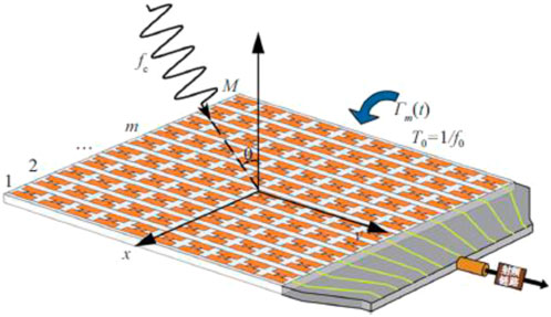
Figure 1. Metasurface model for single channel received signal.
Assume that the far-field transmitter transmits L independent narrowband signals of the same frequency
Among them,
Among them,
Where,
Among them,
It can be seen from Equation 5 that due to the time control of the metasurface, the incident signal will produce a nonlinear phenomenon, which is characterized by the generation of a large number of harmonics in addition to the fundamental component. That is, the signal spectrum is distributed on an infinite number of frequency points
The schematic diagram of TVM’s virtual multi-channel principle is shown in Figure 2. In one symbol period, the TVM unit changes N times, which is equivalent to N heterogeneous array patterns observing the signal separately, thus constructing an N-dimensional virtual channel. Under ideal conditions, in order to fully utilize the TVM array’s degrees of freedom (DoF), the number of states N needs to be no less than the number of arrays M.
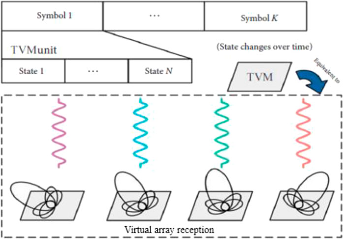
Figure 2. Metasurface model for virtual multi-channel received signal.
For an M-column TVM, when N ≥ M, that is, when the number of virtual channels is not less than the number of metasurface columns, the theoretically optimal DOA estimation result can be obtained. When 2 ≤ N < M, the number of channels is insufficient, resulting in insufficient estimation freedom, and the DOA estimation accuracy will decrease as the number of channels N decreases, and the maximum number of estimated sources becomes N - 1. When the number of states N is the minimum value 2, the TVM control rate achieves the theoretical maximum value
(1) When
(2) When
(3) When
3 Proposed methodology
According to the analysis in Section 1, when the synchronous control method switches the state of the TVM unit, the starting time of each column unit is the same. When the control rate is determined, the number of states N is also determined. When
3.1 Asynchronous control method
Considering the nature that each unit response of TVM will last for a period of time, this paper staggers the start time of unit changes in different columns so that the start time of each unit control of TVM is spaced out within a response duration. At this time, the duration of a single state is shortened, and multiple different responses are realized within a response duration, which is equivalent to increasing the number of virtual channels and improving the DOA estimation accuracy. The schematic diagram of the asynchronous control method is shown in Figure 3.
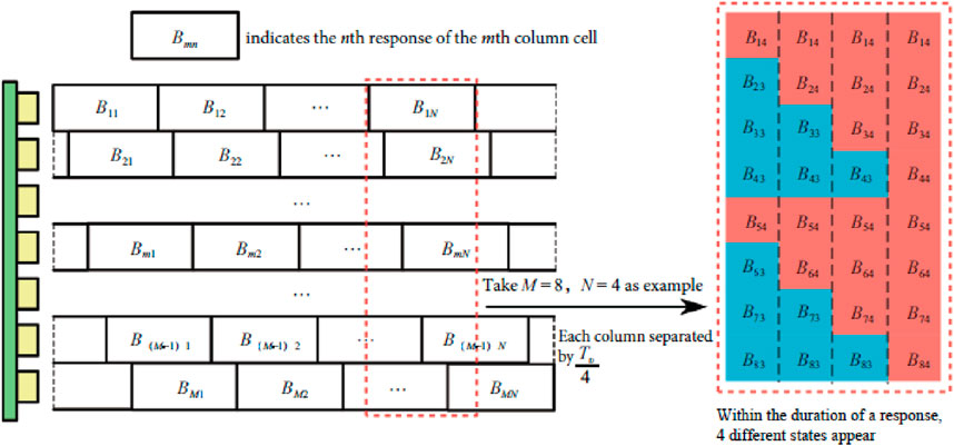
Figure 3. Schematic diagram of the asynchronous control method principle.
In the asynchronous control method, it is assumed that each TVM unit has N different states in each control cycle, the duration of a state is
By using the asynchronous control method, the number of original states can be increased to
For ease of understanding, the subsequent analysis is based on the PIN diode TVM for theoretical explanation. Each unit controls the reflection coefficient of the unit by applying a control voltage to the PIN diode to achieve 1 bit of control capability. At this time, the time control function of the TVM can be expressed as: A periodic square wave signal, including high level “1” and low level “0”. The schematic diagram of Hadamard matrix asynchronous control is shown in Figure 4. It shows the state of the TVM after asynchronous control when
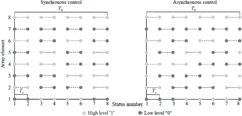
Figure 4. Schematic diagram of Hadamard matrix asynchronous control.
3.2 Sparse representation of received signal
The single-channel TVM receiving signal
Among them,
Among them,
The array flow matrix
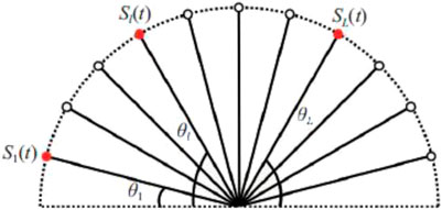
Figure 5. Schematic diagram of spatial sparsity of incident signal.
Therefore, by evenly dividing the space into
At this time,
Among them,
3.3
In the field of spatial signal processing, the sparsity of the signal in space must exist and the sparsity is high enough, so the compressed sensing theory can be applied to solve the DOA estimation value. The
Among them,
Define
By performing dimensionality reduction processing on the sparse signal vector Sˉ(n) and the noise vector
At this time, the received signal matrix after dimension reduction can be expressed by Equation 17:
From Equation 17, we can see that the singular value decomposition processes the columns of the received signal matrix without changing the position of the non-zero rows. The dimension of the received signal matrix is reduced from
Among them,
For the convenience of solving, the constrained optimization problem is transformed into an unconstrained optimization problem through the penalty function method expressed by Equation 19:
Among them,
4 Simulation results
This section evaluates the feasibility of estimating DOA by the asynchronous control method proposed in this paper through numerical simulation. Then, by comparing with the existing methods, the effectiveness of the asynchronous control method proposed in this paper is proved. All simulation experiments were carried out 1,000 times of Monte Carlo simulation. In the simulation experiment, this paper sets the incident signal bandwidth to 5 MHz and the control frequency of the TVM unit to 20 MHz. In the synchronous control method, up to four different states can be achieved in one code element period. In the asynchronous control method, in order to achieve the estimation performance of eight columns of TVM, let
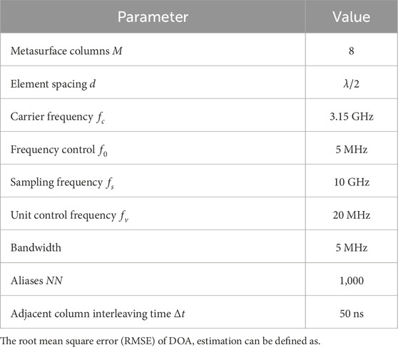
Table 1. Simulation parameters.
Where
4.1 Algorithm effectiveness
The spatial spectra with incident directions of −25° and 20° and the spatial spectra with incident directions of -1° and 1° are shown in Figures 6, 7, respectively. It compares the spatial spectra using the MUSIC algorithm and the asynchronous control method proposed in this paper. As can be seen from Figures 6, 7, the proposed method not only has a sharper spatial spectrum peak, but also has lower side lobes generated by interference signals, and can also effectively distinguish signals with close intervals in the incident direction. The MUSIC algorithm can distinguish signals that are far apart, but cannot distinguish adjacent signals. Therefore, the proposed asynchronous control method has higher resolution.
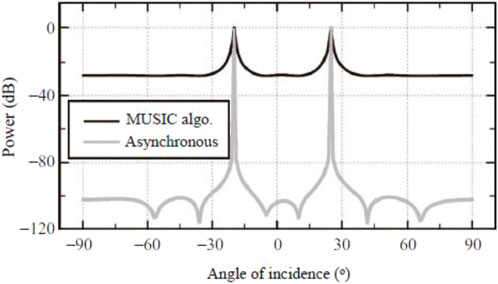
Figure 6. Spatial spectrum comparison at incident directions of −25° and 20°.
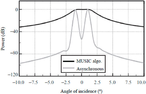
Figure 7. Spatial spectrum comparison at incident directions of -1° and 1°.
The spatial spectra corresponding to seven and three incident signals are shown in Figures 8, 9 respectively. Under the simulation parameters in Table 1, the number of virtual channels N = 4. Figure 8 shows the spatial spectrum function corresponding to the incident angle uniformly distributed between −45° and 45° when the number of incident signals L = 7. It can be seen from Figure 8 that both the asynchronous control method and the multi-channel array can obtain correct DOA estimation results, but the spatial spectrum sidelobes of the asynchronous control method are lower and the anti-interference ability is stronger, which is due to the gain brought by the heterogeneous directional pattern reception. In particular, when the synchronous control method is used, the spatial spectrum cannot be obtained because the number of virtual multi-channels is less than the number of incident signals.
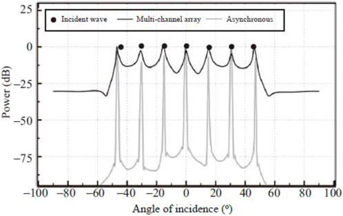
Figure 8. 7-way incident signal corresponding to the spatial spectrum.
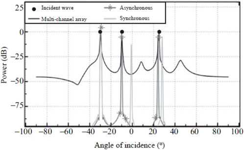
Figure 9. 3-way incident signal corresponding to the spatial spectrum.
Figure 9 shows the corresponding spatial spectrum function when the incident direction is (−30°, −10°, 25°). It can be seen from Figure 9 that although the synchronous control method can obtain an effective spatial spectrum function, the estimation error is large and DOA estimation cannot be achieved. The spatial sidelobe power of the asynchronous control method and the synchronous control method is lower than that of the multi-channel array, which proves that the DOA estimation method based on TVM has better anti-interference performance.
4.2 DOA estimation accuracy
The asynchronous control method proposed in this paper is compared with the synchronous control method and the classic MUSIC and l1-SVD algorithms in the multi-channel array. The change of DOA estimation RMSE with SNR under different methods is shown in Figure 10, where the number of aliases is 1,000 and the incoming wave direction is (−20°, 30°). As shown in Figure 10, the DOA estimation accuracy of the asynchronous control method proposed in this paper and the l1-SVD algorithm implemented by the multi-channel array is basically the same. At the same time, the RMSE estimated by the synchronous control method is higher and the DOA estimation accuracy is poor, which proves that when the control rate is insufficient, the DOA estimation accuracy of the synchronous control method is low, but the asynchronous control method can effectively improve the DOA estimation accuracy and obtain the theoretically optimal DOA estimation result, which proves the effectiveness of the asynchronous control method proposed in this paper.
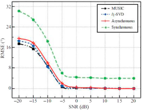
Figure 10. The variation of RMSE of DOA estimation with SNR under different methods.
The variation of DOA estimation RMSE with the number of sources under different methods is shown in Figure 11, where the number of aliases is 1,000 and the SNR is 0 dB. As shown in Figure 11, the synchronous control method can only obtain effective DOA estimation results when there are less than three sources, and the estimated RMSE is high and the DOA estimation accuracy is poor. When the number of sources exceeds 4, no effective DOA estimation results can be obtained. This is because the number of virtual multi-channels obtained by the synchronous control method is insufficient when the control rate is insufficient, and the full information of the array cannot be fully utilized. In addition, the DOA estimation accuracy of the asynchronous control method and the l1-SVD algorithm implemented by the multi-channel array is basically the same, which proves the effectiveness of the asynchronous control method proposed in this paper.
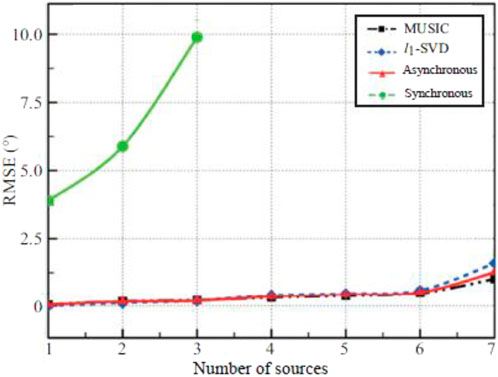
Figure 11. The variation of RMSE of DOA estimation with the number of sources under different methods.
5 Conclusion
This paper proposes a novel time-varying metasurface based DOA estimation method using the idea of asynchronous control. When the TVM unit control rate is limited by materials, the start time of the change of different column units is staggered to obtain multiple different responses within a state duration. In view of the problem of insufficient control rate, the TVM unit state duration is fully utilized to increase the number of virtual multi-channels. Then, a new measurement matrix is obtained according to the asynchronous control codeword, which is used to evenly divide the signal space and obtain a sparse representation of the received signal. Finally, the l1-SVD algorithm based on asynchronous control is used to realize DOA estimation. The simulation results verify the effectiveness of the proposed method. Compared with the existing synchronous control method, the DOA estimation performance has been greatly improved and can approach the theoretical optimal DOA estimation result. The future work will be to consider THz frequency and other operating conditions.
Data availability statement
The original contributions presented in the study are included in the article/supplementary material, further inquiries can be directed to the corresponding authors.
Author contributions
KA: Methodology, Writing – review and editing, Software, Supervision, Writing – original draft, Investigation, Visualization, Validation, Conceptualization, Data curation. NS: Writing – review and editing, Validation, Conceptualization, Investigation, Writing – original draft, Software, Formal Analysis, Methodology, Resources, Visualization, Project administration. JH: Supervision, Writing – review and editing, Investigation, Writing – original draft, Conceptualization, Data curation, Visualization, Resources, Validation, Project administration. JE-G: Writing – review and editing, Formal Analysis, Methodology, Validation, Supervision, Writing – original draft, Software, Resources, Conceptualization. IH: Project administration, Visualization, Funding acquisition, Conceptualization, Resources, Validation, Formal Analysis, Software, Writing – review and editing, Methodology, Supervision, Data curation, Writing – original draft, Investigation.
Funding
The author(s) declare that financial support was received for the research and/or publication of this article. This work was supported by Princess Nourah bint Abdulrahman University Researchers Supporting Project number (PNURSP2025R66), Princess Nourah bint Abdulrahman University, Riyadh, Saudi Arabia.
Conflict of interest
Author IH was employed by Deep Tech As. The remaining authors declare that the research was conducted in the absence of any commercial or financial relationships that could be construed as a potential conflict of interest.
Generative AI statement
The author(s) declare that no Generative AI was used in the creation of this manuscript.
Publisher’s note
All claims expressed in this article are solely those of the authors and do not necessarily represent those of their affiliated organizations, or those of the publisher, the editors and the reviewers. Any product that may be evaluated in this article, or claim that may be made by its manufacturer, is not guaranteed or endorsed by the publisher.
References
1. Wang T, Han J, Ma X, Liu H, Li L. Frequency-diverse MIMO metasurface antenna for computational imaging with aperture rotation technique. Front Mater (2023) 9:1–13. doi:10.3389/fmats.2022.1112339
2. Venneri F, Costanzo S, Borgia A. Fractal metasurfaces and antennas: an overview of advanced applications in wireless communications. Appl Sci (2024) 14(7):1–17. doi:10.3390/app14072843
3. Awan W, Hussain N, Park S, Kim N, “Intelligent metasurface based antenna with pattern and beam reconfigurability for internet of things applications,” Alexandria Eng J (2024) 92, pp. 50–62. doi:10.1016/j.aej.2024.02.034
4. Alibakhshikenari M, Babaeian F, Virdee B, Aissa S, Azpilicueta L, See C, et al. A comprehensive survey on various decoupling mechanisms with focus on metamaterial and metasurface principles applicable to SAR and MIMO antenna systems. IEEE Access (2020) 8:192965–3004. doi:10.1109/access.2020.3032826
5. Alibakhshikenari M, Virdee B, Azpilicueta L, Moghadasi M, Akinsolu M, See C, et al. A comprehensive survey of Metamaterial transmission-line based antennas: design, challenges, and applications. IEEE Access (2020) 8:144778–808. doi:10.1109/access.2020.3013698
6. Althuwayb A, Alibakhshikenari M, Virdee B, Rashid N, Kaaniche K, Atitallah A, et al. Metasurface-inspired flexible wearable MIMO antenna array for wireless body area network applications and biomedical telemetry devices. IEEE Access (2022) 11:1039–56. doi:10.1109/access.2022.3233388
7. Alibakhshikenari M, Ali E, Soruri M, Dalarsson M, Moghadasi M, Virdee B, et al. A comprehensive survey on antennas on-chip based on metamaterial, metasurface, and substrate integrated waveguide principles for millimeter-waves and terahertz integrated circuits and systems. IEEE Access (2022) 10:3668–92. doi:10.1109/access.2021.3140156
8. Kenari MA. Printed planar patch antennas based on metamaterial. Int J Electronics Lett (2013) 2(1):37–42. doi:10.1080/21681724.2013.874042
9. Alibakhsikenari M, Movahhedi M, Naderian H. A new miniature ultra wide band planar microstrip antenna based on the metamaterial transmission line. In: IEEE asia-pacific conference on applied electromagnetics (APACE) (2012). p. 293–7.
10. Hou L, Jin L, Huang K, Xiao S, Lou Y, Chen Y. Beamspace spatial music DOA estimation method using dynamic metasurface antenna. Entropy (2025) 27(4):1–15. doi:10.3390/e27040335
11. Yildirim H, Storrer L, Doncker P, Louveaux J, Horlin F. A multi-antenna super-resolution passive Wi-Fi radar algorithm: combined model order selection and parameter estimatoin. IET Radar, Sonar and Navigation (2022) 16(8):1376–87. doi:10.1049/rsn2.12267
12. Jung Y, Jeon H, Lee S, Jung Y. Scalable ESPRIT processor for direction-of-arrival estimation of frequency modulation continuous wave radar. Electronics (2021) 10(6):1–15. doi:10.3390/electronics10060695
13. Zhu Y, Zhang W, Yi H, Xu H. Enhanced root-music algorithm based on matrix reconstruction for frequency estimation. Sensors (2023) 23(8):1829–15. doi:10.3390/s23041829
14. Chen G, Su X, He L, Guan D, Liu Z. Coherent signal DOA estimation method based on space-time-coding. Remote Sensing (2025) 17(2):1–13. doi:10.3390/rs17020218
15. Yao L, Zhang R, Hu C, Wu W. Off-grid DOA estimation for metasurface antenna systems using sparse Bayesian learning. AEU – Int J Electronics Commun (2025) 190:155615–2. doi:10.1016/j.aeue.2024.155615
16. Zhou C, Gu Y, Fan X, Shi Z, Mao G, Zhang YD. Direction-of-arrival estimation for coprime array via virtual array interpolation. IEEE Trans Signal Process (2018) 66(22):5956–71. doi:10.1109/tsp.2018.2872012
17. Hu D, He S, Li S, Zhu W. A dynamic beam switching metasurface based on angular mode-hopping effect. Front Phys (2024) 12:1–13. doi:10.3389/fphy.2024.1392115
18. Pertsch T, Xiao S, Majumdar A, Li G. Optical metasurfaces: fundamentals and applications. Photon Res (2023) 11(5):1–15. doi:10.1364/prj.487440
19. Hou J, Zhang X, Guo Y, Zhang R, Guo M. Design of electromagnetic metasurface using two dimensional crystal nets. Scientific Rep (2023) 13(7248):7248–14. doi:10.1038/s41598-023-32660-y
20. Yang W, Qin J, Long J, Yan W, Yang Y, Li C, et al. A self-biased non-reciprocal magnetic metasurface for bidirectional phase modulation. Nat Electronics (2023) 6:225–34. doi:10.1038/s41928-023-00936-w
21. Hoang T, Fusco V, Abbasi M, Yurduseven O. Single-pixel polarimetric direction of arrival estimation using programmable coding metasurface aperture. Scientific Rep (2021) 11:23830–14. doi:10.1038/s41598-021-03228-5
22. He C, Cao A, Chen J, Liang X, Zhu W, Geng J, et al. Direction finding by time-modulated linear array. IEEE Trans Antennas Propagation (2018) 66(7):3642–52. doi:10.1109/tap.2018.2835164
23. Chen X, Zhang L, Liu S, Cui TJ. Artificial neural network for direction-of-arrival estimation and secure wireless communications via space-time-coding digital metasurfaces. Adv Opt Mater (2022) 10(23):1–16. doi:10.1002/adom.202201900
24. Dai J, Tang W, Wang M, Chen MZ, Cheng Q, Jin S, et al. Simultaneous in situ direction finding and field manipulation based on space-time-coding digital metasurface. IEEE Trans Antennas Propagation (2022) 70(6):4774–83. doi:10.1109/tap.2022.3145445
25. Fang X, Li M, Han J, Ramaccia D, Toscano A, Bilotti F, et al. Accurate direction-of-arrival estimation method based on space-time modulated metasurface. IEEE Trans Antennas Propagation¸ (2022) 70(11):10951–64. doi:10.1109/tap.2022.3184556
26. Fu H, Dai F, Hong L. Two-dimensional off-grid DOA estimation with metasurface aperture based on MMV sparse Bayesian learning. IEEE Trans Instrumentation Meas (2023) 72:1–18. doi:10.1109/tim.2023.3318716
27. Huang M, Zheng B, Cai T, Li X, Liu J, Qian C, et al. Machine-learning-enabled metasurface direction of arrival estimation. Nanophotonics (2022) 11(9):1–18. doi:10.1515/nanoph-2021-0663
28. Carlon J, Castellanos M, Heath R. Hierarchical codebook design with dynamic metasurface antennas for energy-efficient arrays. IEEE Trans Wireless Commun (2024) 23(10):14790–804. doi:10.1109/TWC.2024.3419107
29. Qian C, Kaminer I, Chen H. A guidance to intelligent metamaterials and metamaterials intelligence. Nat Commun (2025) 16:1154–26. doi:10.1038/s41467-025-56122-3
Keywords: metasurface, DOA estimation, spectral aliasing, beamforming, array antenna
Citation: Alsufiani KD, Soliman NF, Herrera J, Escorcia-Gutierrez J and Hameed IA (2025) Novel time-varying metasurface design for enhanced DOA estimation based on sparse signal recovery. Front. Phys. 13:1602304. doi: 10.3389/fphy.2025.1602304
Received: 29 March 2025; Accepted: 28 April 2025;
Published: 30 May 2025.
Edited by:
Imran Khan, COMSATS Institute of Information Technology, PakistanReviewed by:
Dragan Perakovic, University of Zagreb, CroatiaMohammad Alibakhshikenari, Universidad Carlos III de Madrid, Spain
Kemal Gokhan Nalbant, Beykent University, Türkiye
Copyright © 2025 Alsufiani, Soliman, Herrera, Escorcia-Gutierrez and Hameed. This is an open-access article distributed under the terms of the Creative Commons Attribution License (CC BY). The use, distribution or reproduction in other forums is permitted, provided the original author(s) and the copyright owner(s) are credited and that the original publication in this journal is cited, in accordance with accepted academic practice. No use, distribution or reproduction is permitted which does not comply with these terms.
*Correspondence: José Escorcia-Gutierrez, amUuc2NvcmNpNTZAY3VjLmVkdS5jbw==