 Benhong Ouyang1,2
 Jianjun Yuan
- 1State Key Laboratory of Power Grid Environmental Protection, Wuhan, China
- 2China Electric Power Research Institute Co., Ltd., Wuhan, China
The interfacial pressure between cable accessories and cable insulation plays a decisive role in the insulation characteristics of the accessories and the long-term reliable operation of the cable. Considering the actual rough contact interface between the cable body and the intermediate joint, a finite element simulation model of stress field-sound field coupling was constructed using points with Gaussian probability distribution. Based on this model, the differences in echo signals in the time domain and frequency domain at different positions of the cable accessories, as well as the differences in echo signals under different interfacial pressures at the same position, were analyzed. Subsequently, the functional relationship between interfacial pressure and nonlinear parameters was fitted. Finally, a nonlinear ultrasonic testing platform was established to measure the interfacial pressure at different positions of the cable intermediate joint, verifying the accuracy of the relationship between interfacial pressure and nonlinear parameters. The experimental and simulation results showed consistent patterns in the time domain and frequency domain of the echo signals, with the nonlinear parameters increasing as the interfacial pressure increased. The experimental results indicated that the detected nonlinear parameter value was around 7.46 × 10⁻³ (with an error range within 5.80%), corresponding to an interfacial pressure of 0.21 MPa; and the detected nonlinear parameter value was around 6.38 × 10⁻³ (with an error range within 7.60%), corresponding to an interfacial pressure of 0.16 MPa. The nonlinear parameters can characterize the interfacial pressure at different locations, verifying the validity of the simulation fitting function and providing a new approach for measuring the interfacial pressure of cable accessories.
1 Introduction
With the continuous deepening of urbanization in China, the utilization rate of cable in some mega and super-large cities has been increasing. Cables have become the lifeline of urban operations, making it increasingly important to ensure their safe operation. According to statistics, excluding external damage, intermediate joint failures account for 60% of cable failures [1]. The interfacial pressure is a core element in the structural design of cable accessories, and integral prefabricated insulation components are an important part of the cable accessory structure. The interfacial pressure is achieved through the interference fit between the cable accessory and the cable body insulation layer. If the interfacial pressure is too low, it cannot meet the electrical strength requirements of the cable accessory, leading to the formation of air gaps and cavities, which can cause interfacial breakdown. Conversely, if the interfacial pressure is too high, it makes the installation of the cable accessory difficult, potentially causing the accessory to crack or break during installation, and over time, stress relaxation may occur. Studies have shown that an interfacial pressure range of 0.10 MPa∼0.25 MPa can ensure good insulation performance and electrical strength for intermediate joints [2, 3].
Current methods for detecting interfacial pressure in intermediate joints include sensor methods [4–6] and finite element analysis methods [7–9]. The built-in sensor method involves attaching a thin-film sensor to the contact interface between the intermediate joint and the cable body. This method is limited to factory testing of intermediate joints and is not suitable for installed joints due to the damage it causes to the cable body’s insulation structure. Some researchers have proposed using external fiber Bragg grating curvature sensors to detect the interfacial pressure by measuring the expansion rate of the cable accessory [10, 11]. However, this method is significantly affected by the operating environment of the cable, and the accuracy of the sensors needs improvement. Finite element analysis methods simulate the mechanical performance of cable intermediate joints under different temperatures [12] and interference fits [13], but it is difficult to determine the interfacial pressure and contact conditions of newly installed cable joints in the field. Therefore, there is an urgent need for a non-destructive testing method suitable for measuring the interfacial pressure of in-stalled cable intermediate joints.
The application of ultrasonic nonlinear effects for stress detection has been studied by many scholars, including the use of ultrasonic nonlinear effects to characterize the load of pin connections [14], the axial stress of bolts [15], the tensile stress of metals [16], the structural stress of composite materials [17], and the contact stress of flat silicone rubber [18]. These studies have experimentally verified the mapping relationship between ultrasonic nonlinear parameters and stress. Biwa et al. [19] and Kim et al. [20] theoretically explained the relationship between interfacial pressure and the acoustic nonlinear parameters of the contact interface, constructing a stress model for the interaction between ultrasound and the interface, providing theoretical support for the application of ultrasonic nonlinear technology in interfacial pressure detection. Basu [21] applied the ultrasonic nonlinear harmonic effect to detect internal stress in concrete structures, establishing a constitutive model for the relationship between concrete stress and ultrasonic nonlinear parameters. The accuracy of the model was verified experimentally, showing that nonlinear parameters can reflect changes in concrete stress. Fang Chunhua et al. [18] used nonlinear ultrasound to detect the interfacial pressure between flat silicone rubber and cross-linked polyethylene, experimentally verifying the correlation between the nonlinear characteristic parameters of the interface echo signal and the interfacial pressure. However, the surface roughness of cross-linked polyethylene and the use of flat silicone rubber instead of integral prefabricated cable accessories were not considered.
This paper proposes a non-destructive testing method for the interfacial pressure of 110 kV integral prefabricated cable intermediate joints based on the ultrasonic nonlinear effect, aiming to use ultrasonic nonlinear parameters to characterize the interfacial pressure at the contact interface of intermediate joints. First, based on the axial distribution of interfacial pressure and magnetic field characteristics of 110 kV integral prefabricated intermediate joints, two typical positions were selected as research subjects. A rough contact interface model was established based on the surface roughness parameters of the cable body and the prefabricated intermediate joint under actual working conditions. The ultrasonic propagation mechanism at the interface of the typical positions was analyzed through simulation, obtaining the mapping relationship between nonlinear parameters and interfacial pressure, and fitting the curve expression of the mapping relationship. A nonlinear ultrasonic testing platform was set up to detect the echo signals at different positions of the prefabricated insulation component. The consistency between the experimental results and the simulation results in the time/frequency domain characteristics of the echo signals was analyzed, verifying the validity of the simulation-derived functional relationship between nonlinear parameters and interfacial pressure. This research provides a reference for the installation and maintenance of 110 kV integral prefabricated cable intermediate joints.
2 Contact acoustic nonlinear theory
The nonlinear theory of contact interfaces is one of the important mechanisms causing acoustic nonlinearity in solid-solid contacts. External loading pressure causes the micro-asperities at the contact interface to come into contact. Due to the complete and incomplete contact between micro-asperities, irregular micro-asperities generate nonlinear strain, leading to a nonlinear relationship between stress and strain at the interface [15]. Therefore, the relationship between the external load and the strain at the contact interface can be expressed as Equation 1:
where P is the interfacial pressure, P0 is the initial interface pressure, Δh is the strain at the contact interface, K1 is the linear contact stiffness, and K2 is the nonlinear contact stiffness, which characterize the nonlinear stress-strain relationship at the contact interface. Here,
where C and m are coefficients related to the roughness characteristics of the interface.
When ultrasonic waves act on a rough contact interface, the nonlinear strain of the micro-asperities at the contact interface causes slight perturbations in the ultrasonic signal energy, generating second harmonics [14].
By combining Equations 2, 3 with the formula for the fundamental/second harmonic amplitude of the interface reflected wave signal in Ref. [14], the relationship between interfacial pressure and the fundamental/second harmonic amplitude can be obtained as:
Here, A is the excitation signal amplitude, A1 and A2 are the fundamental and harmonic wave amplitudes of the interface-reflected signal, respectively, ρ is the material density, and c is the ultrasonic wave propagation velocity in the material. Based on the fundamental and second harmonic amplitudes, the ultrasonic non-linear parameter can be obtained, and the relationship between the nonlinear parameter and the interfacial stiffness can be established as:
As shown Equation 7, substituting Equations 2, 3 into Equation 6 yields the functional relationship between the ultrasonic nonlinear parameter β and the interfacial pressure P:
3 Finite element analysis
3.1 Construction of the finite element simulation model
The structure of the integral prefabricated insulation component made of silicone rubber is shown in Figure 1. The cable outer shield and the stress cone, inner and outer shield parts of the prefabricated insulation component are made of semi-conductive silicone rubber, while the main insulation of the prefabricated component is made of silicone rubber, and the main insulation of the cable is made of cross-linked polyethylene.
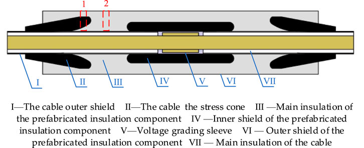
Figure 1. Prefabricated insulator and cable body mating structure diagram.
The propagation of ultrasonic waves in solids is influenced by the material properties and different contact interfaces. Based on the axial distribution of interfacial pressure in intermediate joints [6] and the magnetic field distribution characteristics [22], two typical positions were selected as research subjects for detecting interfacial pressure using ultrasonic nonlinear technology (highlighted in red in Figure 1). Position “1” is at the root of the stress cone, and position “2” is at the insulation part of the intermediate joint.
Considering that the actual surface roughness of the prefabricated insulation component and the cable body insulation affects the actual contact area, the surface roughness of the prefabricated insulation component was measured using white light interferometry. The surface roughness and microscopic morphology of the cross-linked polyethylene surface of the cable body, prepared according to the installation instructions of a domestic 110 kV cable intermediate” joint manufacturer, are shown in Figure 2. Based on Figure 2, the average surface roughness was measured along a randomly selected curve in the x-direction. The average surface roughness of the prefabricated insulation component and the cross-linked polyethylene surface were 2.19 μm and 2.45 μm, respectively, with micro-asperity peak heights of 32.31 μm and 136.42 μm, respectively. A series of points with Gaussian probability distribution [23] were generated using MATLAB software to form the rough distribution of micro-asperities in the COMSOL simulation software.
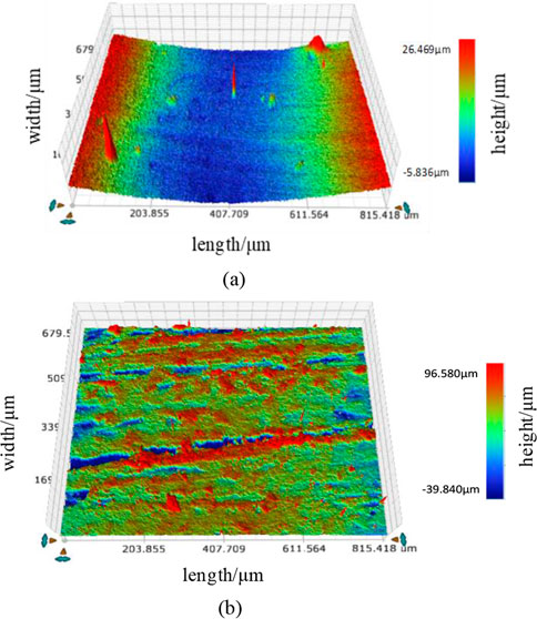
Figure 2. Surface roughness topography of the contact interface. (a) Surface roughness morphology of the prefabricated insulation component. (b) Surface roughness morphology of cross-linked polyethylene.
The COMSOL simulation software was used to simulate the nonlinear ultrasound at positions “1” and “2” in the prefabricated insulation component shown in Figure 1. The dimensions (width × height) of the simulation model were 8 mm × 55 mm, with the insulation component thickness set to 45 mm and the lower cross-linked polyethylene thickness set to 10 mm. Since silicone rubber and semi-conductive silicone rubber are ultrasonic elastic materials, meaning there is a nonlinear relationship between stress and strain, the Yeoh hyperelastic material model [13] was selected for the material parameters to better characterize the contact stress at the interface between silicone rubber and semi-conductive silicone rubber. The material parameters are listed in Table 1. From a practical perspective, ultrasonic testing is performed on the contact interface under stress. Therefore, in the simulation, the model involves the coupling of the stress field and the acoustic field. This paper uses sequential coupling. First, a steady-state analysis of the contact interface stress is performed under the solid mechanics physics field, with the rough contact interface set as the contact pair and the lower surface set with fixed constraint boundary conditions. A specified load is applied to the upper surface to generate stress at the contact interface. The stressed model is then used as the basis for the transient analysis of the acoustic field, meaning the geometric mesh of the stressed model is imported into the initial geometric model of the acoustic field analysis. In the acoustic field, solid mechanics and electrostatics are coupled, with a 2 mm × 2 mm geometry set as piezoelectric material added to the upper surface. The lower boundary of the piezoelectric material is set with an excitation potential to simulate the probe generating the excitation signal. The sides of the geometry are set as low-reflection boundaries to reduce interference with the echo signal. Based on pre-experiments, the excitation signal frequency was set to 1.50 MHz with 10 cycles. According to the COMSOL simulation software’s official guidelines for ultrasonic nonlinear simulation, the mesh for the transient analysis of the acoustic field was di-vided into 1/8 of the ultrasonic wavelength, with a time step of 16.67 ns.
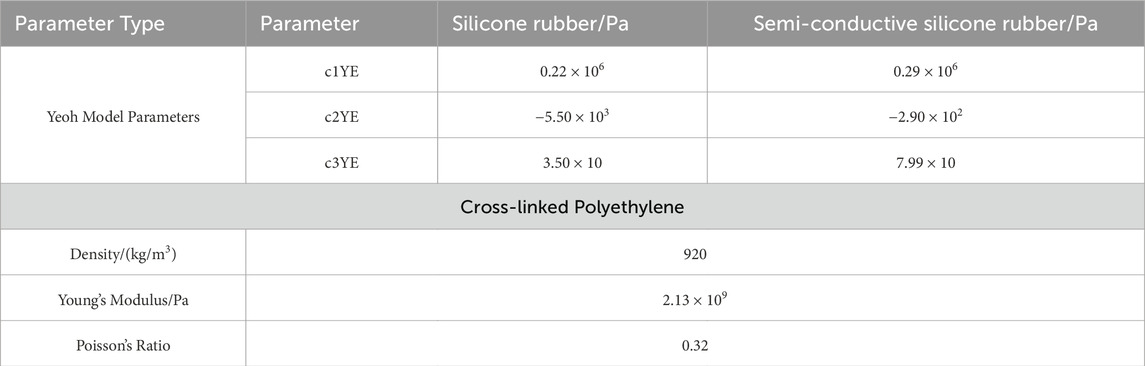
Table 1. Material properties.
3.2 Analysis of echo signals at different positions
Figure 3 shows the ultrasonic propagation displacement cloud diagram at the root of the stress cone (position “1”) under 0.10 MPa, and Figure 4 shows the ultrasonic propagation displacement cloud diagram at the insulation part of the intermediate joint (position “2”) under 0.10 MPa. Comparing Figures 3, 4, it can be seen that the curved surface at the root of the stress cone at position “1” causes the reflected ultrasonic signal to refract at a certain angle, causing the two energy signals that should have converged to continue propagating along the refracted angle. As a result, the echo signal amplitude detected at the lower surface of the probe at position “1” is smaller than that at position “2”(as shown in Figure 5a). The reason why the echo signal at position “1” arrives earlier than that at position “2” is that the wave speed of the semi-conductive silicone rubber material at the stress cone is greater than that of the silicone rubber material. Therefore, with the same propagation distance, the echo time is reduced. The primary echo signal in Figure 5a was subjected to Fast Fourier Transform (FFT), and the result was compared with the excitation signal spectrum, as shown in Figure 5b. Under the action of interfacial pressure, harmonics appeared around 3 MHz in the amplitude-frequency diagram of the echo signal, showing obvious nonlinear characteristics. From Figure 5b, it can be seen that the fundamental wave amplitude in the excitation signal amplitude-frequency diagram is larger than that in the echo signal amplitude-frequency diagram at positions “1” and “2”. This is because the high attenuation of ultrasonic signals by silicone rubber causes the primary echo signal amplitude to be smaller than the excitation signal amplitude, resulting in a smaller fundamental wave amplitude after Fourier transform compared to the excitation signal. According to Equations 4, 5, under the same pressure condition (P unchanged), the fundamental/second harmonic amplitude (A1, A2) in the amplitude-frequency diagram of the interface reflected wave signal is positively correlated with the incident wave amplitude A at the contact interface. Therefore, based on the incident wave propagation cloud diagrams at the interface in Figures 3, 4 (at 4.00 × 10⁻⁵ s in Figure 3, and 4.35×10⁻⁵ s in Figure 4), the incident wave amplitude at position “1” is 5.49 × 10⁻⁶ mm, which is smaller than the amplitude of 5.87 × 10⁻⁶ mm at position “2”. This results in smaller fundamental/second harmonic amplitudes at position “1” compared to position “2”, as shown in Figure 5b.
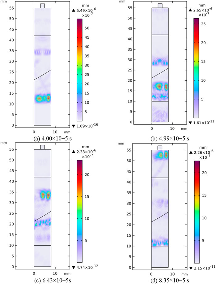
Figure 3. Ultrasonic propagation displacement cloud at the root of the stress cone. (a) 4.00 × 10⁻⁵ s. (b) 4.99 × 10⁻⁵ s. (c) 6.43 × 10⁻⁵s (d) 8.35 × 10⁻⁵ s.
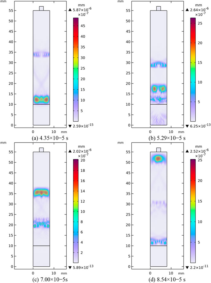
Figure 4. Ultrasonic propagation displacement cloud at the insulation position of the intermediate joint. (a) 4.35 × 10⁻⁵ s. (b) 5.29 × 10⁻⁵ s. (c) 7.00 × 10⁻⁵s (d) 8.54 × 10⁻⁵ s.
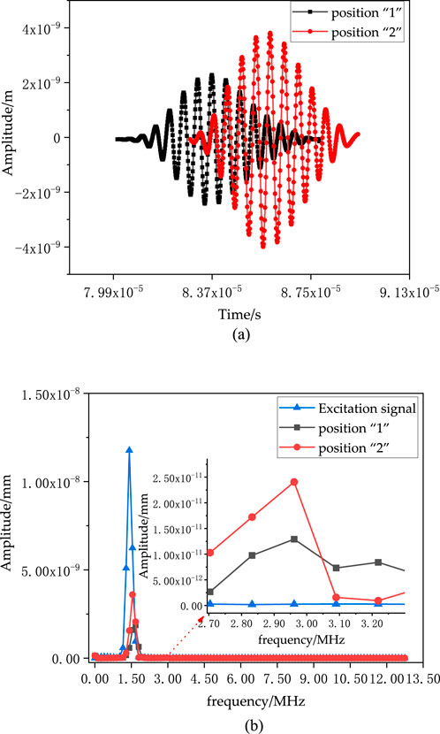
Figure 5. Plot of amplitude and spectrum of primary echo signals at different locations. (a) Echo signal diagram at positions “1” and “2”(0.10 MPa). (b) Excitation signal and echo signal spectrum diagram (0.10 MPa).
3.3 Relationship between nonlinear parameters and interfacial pressure
Figure 6 shows the time-domain echo signals at the root of the stress cone and the insulation part of the intermediate joint under different interfacial pressures. As shown in Figure 6, the echo signal decreases as the interfacial pressure increases. This is because as the pressure increases, the irregular micro-asperities at the rough contact interface deform under force, increasing the actual contact area. Consequently, the component of the incident wave from the upper surface passing through the micro asperities to the lower surface of the cross-linked polyethylene increases, meaning the transmitted wave strengthens and the reflected wave energy decreases. The decrease is more significant in the 0 MPa∼0.15 MPa range because, under low pressure, the contact area of the micro-asperities is small. Increasing the pressure in this range causes the contact area of the rough interface with Gaussian distribution to increase significantly, as shown in Figure 7. A larger contact area results in smaller reflected wave energy, and since the contact area changes significantly in the 0 MPa∼0.15 MPa range, the reflected wave energy changes significantly, meaning the reflected wave amplitude changes significantly. Additionally, as the pressure increases, the echo signal time slightly advances because the increased contact area of the micro-asperities under pressure reduces the contact gap, shortening the ultrasonic propagation distance and thus reducing the propagation time, leading to a decrease in the echo signal time at the contact interface.
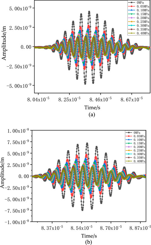
Figure 6. Time-domain signals of interfacial echoes at different pressures. (a) Root of the stress cone. (b) Insulation part of the intermediate joint.
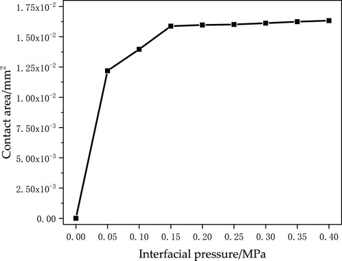
Figure 7. Plot of rough contact area with pressure.
The time-domain echo signals in Figure 6 were subjected to FFT, resulting in the amplitude-frequency diagrams of the echo signals under different pressures shown in Figure 8. From the figure, it can be seen that obvious harmonics appear around 3 MHz, and as the interfacial pressure increases, the fundamental/second harmonic amplitudes in the amplitude-frequency diagrams at positions “1” and “2” decrease. According to Equations 4, 5, at the same position, with the incident wave amplitude A at the interface constant, and the initial roughness parameters C and m unchanged, as the interfacial pressure P increases, A1 and A2 decrease. The gradual decrease in the change of fundamental/second harmonic amplitudes in the amplitude-frequency dia-gram is related to the change in the time-domain echo signal amplitude.
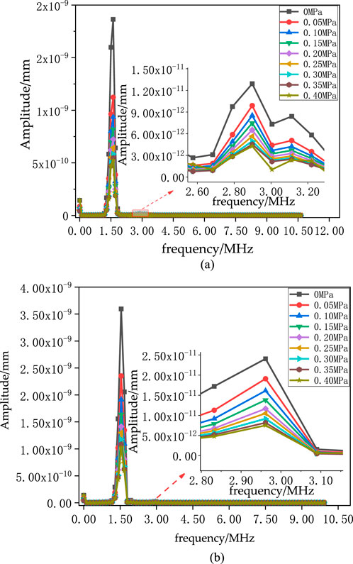
Figure 8. Amplitude-frequency diagram of the echo signal at different pressures. (a) Root of the stress cone. (b) Insulation part of the intermediate joint.
Based on Equation 6, the ultrasonic nonlinear parameter values under different interfacial pressures were calculated and normalized, as shown by the data points in Figure 9. The nonlinear parameters at different positions differ under the same pressure conditions. This is because, under the same pressure, the internal structure and material at positions “1” and “2” are different (as shown in Figure 1), leading to slight differences in the contact state at the interface, resulting in different normalized values of the nonlinear parameters under the same interfacial pressure. The normalized non-linear parameter values at the two positions were fitted, and the fitting curve formula is:
where the coefficient H is 1.74, and the fitting curve correlation coefficient R2 is 0.98.
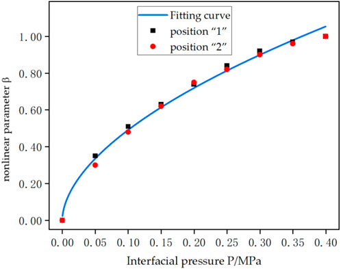
Figure 9. Nonlinear parameters versus interfacial pressure at different locations.
4 Test samples and platform
4.1 Test samples
A 110 kV integral prefabricated cable intermediate joint prefabricated insulation component produced by a manufacturer was selected. The prefabricated insulation component has a length of 680 mm, a thickness of 45 mm, and an inner diameter of 60 mm. According to the manufacturer’s guidelines for the prefabricated insulation component and cable body mating, it is used with a 110 kV cable with a copper conductor cross-section of 800 mm2 and an outer insulation diameter of 70 mm. The interference fit between the prefabricated insulation component and the cable body is 10 mm, which meets the interfacial pressure requirements for the cable intermediate joint. According to the manufacturer’s on-site joint installation guidelines, the cross-linked polyethylene insulation layer of the cable body was polished, and a pre-calibrated thin-film pressure sensor was attached to the cable surface at positions “1” and “2” corresponding to the prefabricated insulation component. The prefabricated insulation component was then placed on the specified position of the cable and left for 2 h to stabilize the pressure value [6].
4.2 Test samples
A nonlinear ultrasonic testing platform was set up as shown in Figure 10. The platform consists of a Tektronix signal generator, an RITEC power amplifier, a low-pass filter, a duplexer, a probe, and an oscilloscope.
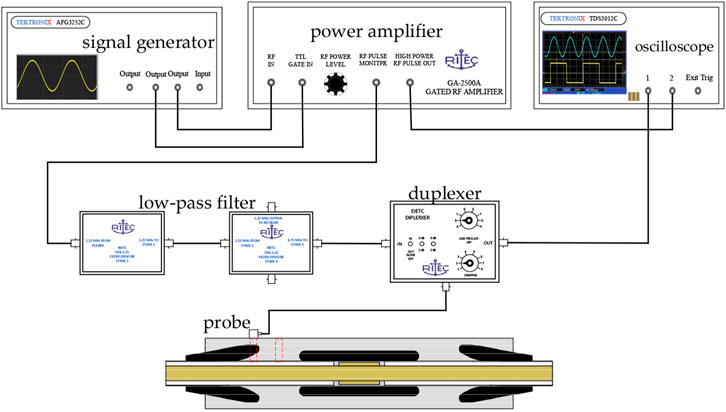
Figure 10. Nonlinear ultrasonic test platform.
The 110 kV prefabricated intermediate joint insulation component has a large thickness, and silicone rubber is a highly attenuating material. The higher the excitation signal frequency, the more severe the attenuation. Therefore, a Hanning window modulated signal with a center frequency of 1.50 MHz and 10 cycles was selected as the excitation signal for the ultrasonic signal generator. The periodic signal generated by the signal generator was amplified by the power amplifier to ensure that the excitation signal energy was sufficient to propagate to the intermediate joint contact interface and receive a clear echo signal. The signal was then passed through a low-pass filter to remove high-frequency noise, ensuring that the excitation signal contained only the 1.50 MHz frequency periodic signal, and that the high-frequency harmonic signals in the echo signal were unrelated to the excitation signal. This test used a single probe to both transmit and receive the signal, so a duplexer was used to separate the excitation signal from the received signal. The output port of the duplexer was connected to the echo signal amplifier to amplify the echo signal, which was then displayed on the oscilloscope.
Since the coupling of the ultrasonic probe with the prefabricated insulation component through coupling agent and the equipment of the nonlinear ultrasonic testing platform may affect the test results, the reliability of the testing platform needed to be verified. By increasing the system excitation signal voltage, the time-domain echo signal at the interface was subjected to Fourier transform to obtain the corresponding spectrum. From the spectrum, the peak amplitude corresponding to the 1.50 MHz frequency was A1, and the peak amplitude corresponding to the 3 MHz frequency was A2. The relationship between A12and A2 was fitted, as shown in Figure 11. The fitting curve formula is
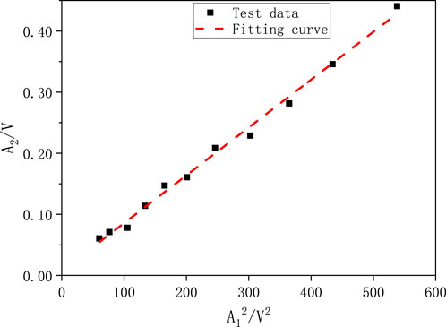
Figure 11. The second harmonic amplitude A2 versus A12.
5 Test results and analysis
The above testing platform was used to measure the ultrasonic echo signals at the root of the stress cone and the insulation part of the 110 kV prefabricated insulation component, as shown in Figure 12.
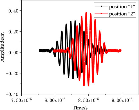
Figure 12. Reflected wave signals at positions “1” and “2”.
As shown in Figure 12, the echo signals obtained from the test are consistent with the simulation results, meaning the echo signal amplitude at position “1” is 21% smaller than that at position “2” due to factors such as the curved surface at the root of the stress cone. The difference in wave speed between the semi-conductive silicone rubber material and the silicone rubber material causes the echo signal at position “1” to arrive 2.40 μs earlier than that at position “2”.
The primary echo signals in Figure 12 were subjected to FFT, resulting in the amplitude-frequency diagrams of the echo signals shown in Figure 13. The amplitude-frequency diagrams at positions “1” and “2” from the test are consistent with the simulation results, showing obvious second harmonics around 3 MHz. Since the reflected wave signal amplitude at position “2” is larger, the fundamental/second harmonic amplitudes after Fourier transform are larger at position “2” than at position “1”.
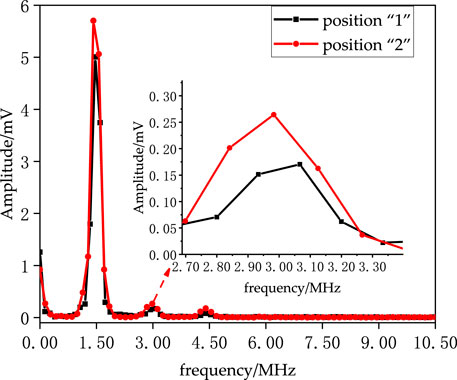
Figure 13. Amplitude-frequency diagram of the echo signal at positions “1” and “2”.
Based on the amplitude-frequency diagrams in Figure 13, the fundamental and second harmonic amplitudes of the echo signals at different positions were extracted. According to Equation 6, the nonlinear parameters at different positions were calculated. The nonlinear parameter at position “1” is 7.90 × 10⁻³, and at position “2” it is 6.38 × 10⁻³. The thin-film pressure sensor showed an interfacial pressure of 0.21 MPa at position “1” and 0.16 MPa at position “2” , which are within the reasonable range, proving that the interference fit is within the safe range.
The above test results verify the validity of the simulation fitting function in Equation 8. Since the echo signal amplitudes from the simulation and the test have different dimensions but the same time/frequency domain trends, the coefficient H in Equation 8 changes, while the power n reflecting the interfacial pressure trend remains unchanged. Substituting the nonlinear parameter of the echo signal at position “2” under 0.16 MPa interfacial pressure into Equation 8 gives a coefficient H of 1.76 × 10⁻². Therefore, the fitting curve (Equation 9) is:
The nonlinear parameter value measured at position “1” and its corresponding pressure value are shown in the first test data in Figure 14. The detected nonlinear parameter value at position “1” is higher than the nonlinear parameter value of 7.46 × 10⁻³ corresponding to 0.21 MPa on the fitting curve.

Figure 14. Test data and fitted test curves.
To further verify the validity of the test curve, five sets of data were detected at the same position, as shown in Figure 14. The other four test data points are scattered near the curve. The nonlinear parameter values detected at position “2” under 0.16 MPa pressure are all smaller than those at position “1” under 0.21 MPa pressure, consistent with the trend of the simulation fitting curve data. However, there are differences between the test data and the simulation data. This is because the actual surface roughness of the cable intermediate joint differs from the rough interface simulated using points with Gaussian probability distribution. Additionally, in the simulation model, the prefabricated insulation component and the cable body are combined through clamping pressure, while in the simulation, the interfacial pressure is applied through a specified load on the upper surface. The difference in the way force is applied in the simulation and the real situation leads to differences in the contact state under stress.
6 Conclusion
Based on nonlinear ultrasonic technology, the nonlinear characteristics of interfacial pressure in 110 kV integral prefabricated cable intermediate joints were studied. The conclusions are as follows:
Based on the rough contact interface with Gaussian probability distribution, a stress field-sound field coupling simulation model was constructed. It was found that the wave speed of semi-conductive silicone rubber is greater than that of silicone rubber, causing the echo time at the root of the stress cone to be smaller than that at the insulation part of the intermediate joint. The curved structure at the root of the stress cone causes the reflected echo signal to refract, resulting in a smaller echo signal amplitude at the root of the stress cone.
At the same position, as the interfacial pressure increases, the contact area increases, and the reflected wave energy of the ultrasonic signal decreases, meaning the echo signal amplitude decreases, and the nonlinear parameter increases. The simulation fitted the mapping relationship between interfacial pressure and nonlinear parameters as
The test results are consistent with the simulation results, meaning the echo signal at the root of the stress cone arrives 2.40 μs earlier, and the echo amplitude is 21% smaller than that at the insulation part of the intermediate joint. The interfacial pressure at the insulation part of the intermediate joint is smaller than that at the root of the stress cone, and the detected nonlinear parameter value at the corresponding position is smaller than that at the root of the stress cone. The test results show that the detected nonlinear parameter value is around 7.46 × 10⁻³ (with an error range within 5.80%), corresponding to an interfacial pressure of 0.21 MPa; and the detected nonlinear parameter value is around 6.38 × 10⁻³ (with an error range within 7.60%), corresponding to an interfacial pressure of 0.16 MPa. The validity of the simulation fitting function relationship between interfacial pressure and nonlinear parameters was verified through testing. The nonlinear parameter value can be used to evaluate interfacial pressure.
Data availability statement
The original contributions presented in the study are included in the article/supplementary material, further inquiries can be directed to the corresponding author.
Author contributions
BO: Data curation, Investigation, Methodology, Project administration, Supervision, Validation, Writing – original draft, Writing – review and editing. RX: Conceptualization, Data curation, Funding acquisition, Investigation, Methodology, Project administration, Supervision, Validation, Writing – original draft, Writing – review and editing. YW: Data curation, Formal Analysis, Methodology, Validation, Writing – original draft. JY: Data curation, Funding acquisition, Investigation, Supervision, Validation, Writing – original draft, Writing – review and editing. KH: Writing – original draft. PZ: Funding acquisition, Investigation, Writing – review and editing. GW: Investigation, Writing – review and editing.
Funding
The author(s) declare that financial support was received for the research and/or publication of this article.
Acknowledgments
We would like to acknowledge all of the authors and peer reviewers for their contributions to this Issue. We would also like to thank the editorial board of Frontiers in Energy Research for trusting our proposal of the Issue and the editorial team at Frontiers in Energy Research for the help in handling the editorial process.
Conflict of interest
Authors BO, RX, YW, JY, KH, PZ, and GW were employed by China Electric Power Research Institute Co., Ltd.
The authors declare that this study received funding from Study on the characterization and measurement of longitudinal ultrasonic nonlinear effect of interface pressure of high voltage cross-linked cable accessories (Science and Technology Project No. 5500-202255290A-2-0-QZ of State Grid Co, Ltd.). The funder had the following involvement in the study: study design, data collection and analysis, and preparation of the manuscript.
Generative AI statement
The author(s) declare that no Generative AI was used in the creation of this manuscript.
Publisher’s note
All claims expressed in this article are solely those of the authors and do not necessarily represent those of their affiliated organizations, or those of the publisher, the editors and the reviewers. Any product that may be evaluated in this article, or claim that may be made by its manufacturer, is not guaranteed or endorsed by the publisher.
References
1. Wang X, Wang CC, Wu K, Tu D, Liu S, Peng J. An improved optimal design scheme for high voltage cable accessories. IEEE Trans Dielectrics Electr Insul (2014) 21:5–15. doi:10.1109/tdei.2013.004102
2. Song MX, Jia ZD. Calculation and simulation of mechanical pressure of XLPE-SR surface in cable joints. 2018 12th international conference on the properties and applications of dielectric materials (ICPADM). IEEE (2018) 1001–5. doi:10.1109/ICPADM.2018.8401207
3. Wang X, Yu D, D SG, Zhang YW, Zhang WH, Wu K, et al. Dealing with some key design problems in HV cable accessory. High Voltage Eng (2018) 44:2710–6. doi:10.13336/j.1003-6520.hve.20180731030
4. Zhang DS, Han YS, Liu HX, Shen WD. Determination of the pressure distribution at the XLPE cable-rubber interface in a self-pressurized joint. High Voltage Eng (2007) 33:173–6. doi:10.3969/j.issn.1003-6520.2007.01.040
5. Tiwari N, Murai Y. Ultrasonic velocity profiler applied to explore viscosity–pressure fields and their coupling in inelastic shear-thinning vortex streets. Experiments in Fluids (2017) 9. doi:10.1007/S00348-021-03257-W
6. Yi DL, Zheng YY, Jiang HY, Gao J, Wu KN, Li JY. Simulation study of interfacial pressure evolution of cable joints considering stress relaxation of silicone rubber. High Voltage Eng (2024) 50:1043–52. doi:10.13336/j.1003-6520.hve.20230247
7. Yan T, Hai G, Hanling M, Tao Z, Yang L, Junlong J. Numerical simulation and experimental study on nonlinear ultrasonic characterization of graphite size in nodular cast iron. Appl Acoust (2025) 227:276–88. doi:10.1016/j.apacoust.2024.110265
8. Jia ZD, Zhang YJ, Fan WN, Zhu B, You J, Lu GJ. Analysis of the interface pressure of cold shrinkable joint of 10 kV XLPE cable. High Voltage Eng (2017) 43:661–5. doi:10.13336/j.1003-6520.hve.20170123041
9. Luo Y, Han ZY, Zhou MY, Haitian W. A sophisticated method of the mechanical design of cable accessories focusing on interface contact pressure. Energies (2020) 13:2976. doi:10.3390/en13112976
10. Wang X, Fan ZY, Wu C, Wang YD, Wu K. Double-optical-fibre temperature compensation method used for interface pressure measurement between cable and accessory at high temperatures. High Voltage Eng (2023) 49:3072–81. doi:10.13336/j.1003-6520.hve.20221519
11. Wang X, Fan ZY, Wu C, Wu K. External fiber grating sensor used for measurement of interface pressure between cable and accessory. High Voltage Eng (2022) 48:38–46. doi:10.13336/j.1003-6520.hve.20210823
12. Disante R, Ghaderi A, Mingotti A, Peretto L, Tinarelli R. Effects of thermal cycles on interfacial pressure in MV cable joints. SENSORS (2020) 20:169. doi:10.3390/s20010169
13. Xie Q, Wang XY, Fu ML, Hui BJ, Liu T. Interference fit and mechanical property computation of silicone rubber accessory in HV cable joint. High Voltage Eng (2018) 44:498–506. doi:10.13336/j.1003-6520.hve.20180131021
14. Huo LS, Zhang CC. Load condition monitoring of pin connection based on nonlinear ultrasonic theory. J Vibration, Meas and Diagn (2023) 43:609–14. doi:10.16450/j.cnki.issn.1004-6801.2023.03.026
15. Pan QX, Chang ML, Pan RP, Xu XY, Li SG, Zhang YM. Research on nonlinear ultrasonic testing technology of bolt axial stress. J Mech Eng (2021) 57:88–95. doi:10.3901/JME.2021.22.088
16. Yan HJ, Xu CG, Xiao DG, Cai HC. Research on nonlinear ultrasonic properties of tension stress in metal materials. J Mech Eng (2016) 52:22–9. doi:10.3901/jme.2016.06.022
17. Mevissen F, Meo M. A nonlinear ultrasonic modulation method for crack detection in turbine blades. Aerospace (2020) 7:72. doi:10.3390/aerospace7060072
18. Fang CH, Liu JB, Sun AQ, Wu JX, Xia R, Ouyang BH, et al. An interface pressure detection method of cable silicone rubber-XLPE based on nonlinear ultrasound. Appl Sciences-basel (2023) 13:5404. doi:10.3390/app13095404
19. Biwa S, Hiraiwa S, Matsumoto E. Experimental and theoretical study of harmonic generation at contacting interface. Ultrasonics (2006) 44:e1319–22. doi:10.1016/j.ultras.2006.05.010
20. Kim JY, Lee JS. A micromechanical model for nonlinear acoustic properties of interfaces between solids. J Appl Phys (2007) 101:043501. doi:10.1063/1.2434939
21. Basu S, Thirumalaiselvi A, Sasmal S, Kundu T. Nonlinear ultrasonics-based technique for monitoring damage progression in reinforced concrete structures. Ultrasonics (2021) 115:106472. doi:10.1016/j.ultras.2021.106472
22. Hu X, Yang SC, Du Q, Chen XR, Tang FX. Radio-frequency detection of partial discharge in power cable joints. IEEE TRANSACTIONS ON POWER DELIVERY (2024) 39:317–24. doi:10.1109/tpwrd.2023.3334310
Keywords: cable accessories, nonlinear ultrasound, interfacial pressure, nonlinear parameters, 110kV cable
Citation: Ouyang B, Xia R, Wang Y, Yuan J, Huang K, Zhao P and Wang G (2025) Characterization of ultrasonic nonlinear properties of interfacial pressure in 110kV integral prefabricated cable intermediate joints. Front. Phys. 13:1603971. doi: 10.3389/fphy.2025.1603971
Received: 07 April 2025; Accepted: 26 May 2025;
Published: 19 June 2025.
Edited by:
Yangyang Chen, Hong Kong University of Science and Technology, Hong Kong SAR, ChinaReviewed by:
Chen Shen, Rowan University, United StatesJinghui Gao, Xi’an Jiaotong University, China
Ming Wu, Xi’an Jiaotong University, China
Copyright © 2025 Ouyang, Xia, Wang, Yuan, Huang, Zhao and Wang. This is an open-access article distributed under the terms of the Creative Commons Attribution License (CC BY). The use, distribution or reproduction in other forums is permitted, provided the original author(s) and the copyright owner(s) are credited and that the original publication in this journal is cited, in accordance with accepted academic practice. No use, distribution or reproduction is permitted which does not comply with these terms.
*Correspondence: Jianjun Yuan, MjQyNDUyNDkyM0BxcS5jb20=