 Hailong Liu1,2,3
 Zi Yang1,2,3
 Yan Gao3
 Lijuan Dong1,2,3Yaru Guo1,2,3Xin Xu1,2,3Tianhua Meng1,2,3Weidong Hu2,4,5Caixia Feng1,2,3*
- 1Institute of Solid State Physics, Shanxi Datong University, Datong, China
- 2Shanxi Province Key Laboratory of Microstructure Electromagnetic Functional Materials, Shanxi Datong University, Datong, China
- 3College of Physics and Electronics, Shanxi Datong University, Datong, China
- 4The School of Integrated Circuits and Electronics, Beijing Institute of Technology, Beijing, China
- 5Terahertz Technology (Datong) Institute, Datong, China
This paper presents a broadband metasurface (MTS) antenna using the characteristic mode analysis (CMA) method for high-frequency gain enhancement. First, by loading four parasitic patches around the 3 × 3 squared patches on the upper layer, the potential bandwidth of the characteristic modes of the MTS is broadened, and the impedance matching of the antenna is improved. As a result, the bandwidth of the proposed antenna is improved. However, the high-frequency realized gain of the antenna is significantly lower than that at low frequency because the mode at the high operating band has radiation null in the boresight direction. To address this, two slots along the x-axis are introduced in part of the unit cells of the MTS, according to the CMA, for mode optimization. The optimized higher-order modes (HOMs) then exhibit broadside radiation patterns at high frequency, leading to a significant improvement in high-frequency realized gain. Specifically, the realized gain at 7 GHz in the boresight direction is enhanced from −1.17 dBi to 9.5 dBi. The simulated and experimental results show that the proposed antenna achieves a 55.2% (4.66 GHz–8.22 GHz) impedance bandwidth for |S11| ≤ −10 dB, with a very flat gain of 7–10 dBi.
1 Introduction
Metasurface (MTS) antennas can achieve low profile, high gain, wide bandwidth [1], and other characteristics due to the great potential of MTS in manipulating electromagnetic waves. Characteristic mode analysis (CMA) [2–4] is often used in MTS antenna design. However, the high operating band of broadband MTS antennas often contains a large number of higher-order modes (HOMs), which have large sidelobes and radiation nulls in the boresight direction [5]. If the unoptimized HOMs are heavily weighted at the high frequency, it will result in a decrease in the high-frequency realized gain of MTS antennas, thereby reducing communication quality [6].
Different methods based on CMA are used to improve the radiation characteristics of MTS antennas [7–16]. For example, cross-polarization is reduced by loading shorting pins [1]. In [7], dual slots are etched on the patch fed by a coaxial probe to reduce H-plane cross-polarization levels, where the realized peak gain reaches 10.1 dBi and the 3 dB gain bandwidth is 22%. The boresight gain is improved in [8] due to the relatively large lateral size that supports in-phase currents, and the feeding position is calculated based on CMA in [9]. The radiation pattern decoupling is achieved in [10]. CMA has also been used for miniaturized MTS antennas [11], filtering MTS antennas [12], and different polarization characteristics of MTS antennas [13–18]. The operating bandwidth is 20.24%, and the isolation is better than 38 dB for the low-profile wideband pattern diversity MTS antenna proposed in [17]. A low-sidelobe dual-beam antenna is proposed in [19] based on MTS with independently regulated amplitude/phase.
Unwanted HOMs that produce large sidelobes could also be suppressed using CMA to improve radiation characteristics, such as by loading the unit cells of the MTS with slots and vias [6], using two types of scatterers [20], or reducing the ground size [21]. A dielectric resonator (DR)-excited wideband MTS antenna is proposed in [22], where the broadside maximum generated by the DR is utilized to enhance the boresight gain of the HOM, according to the superposition principle of radiation patterns.
In this paper, a broadband MTS antenna with parasitic patches for high-frequency gain enhancement is proposed. Four parasitic patches are loaded around the 3 × 3 squared patches on the upper layer of the antenna, which helps the proposed antenna achieve a broad bandwidth. However, the high-frequency realized gain of the antenna is reduced by the radiation nulls in the boresight direction of the HOMs in the high operating band. Subsequently, to optimize HOMs and increase the high-frequency realized gain of the proposed MTS antenna, two slots along the x-axis are introduced in part of the MTS unit cells to interrupt the out-of-phase currents. According to the theory of characteristic modes [2–4], the characteristic modes vary with the structure. Since the optimized HOMs have broadside radiation patterns at the high operating band, the gain of the MTS antenna in the boresight direction will be improved further. The proposed antenna can operate from 4.66 GHz to 8.22 GHz with a very flat realized gain of 7–10 dBi.
2 Design of the broadband metasurface antenna
Figure 1 shows the geometry of the proposed MTS antenna. It consists of two substrate layers and three metal layers. As references, the upper MTS layer of the antenna changes gradually, and they are denoted as types I–Ⅳ and shown in Figures 1a–d, respectively. Type I is a traditional microstrip square patch. As for types II and III, the two groups of coplanar patches with different sizes are named P1 and P2. The parasitic patches are named P3. For the modified type Ⅳ, P2 and P3 are loaded with two slots along the x-axis.
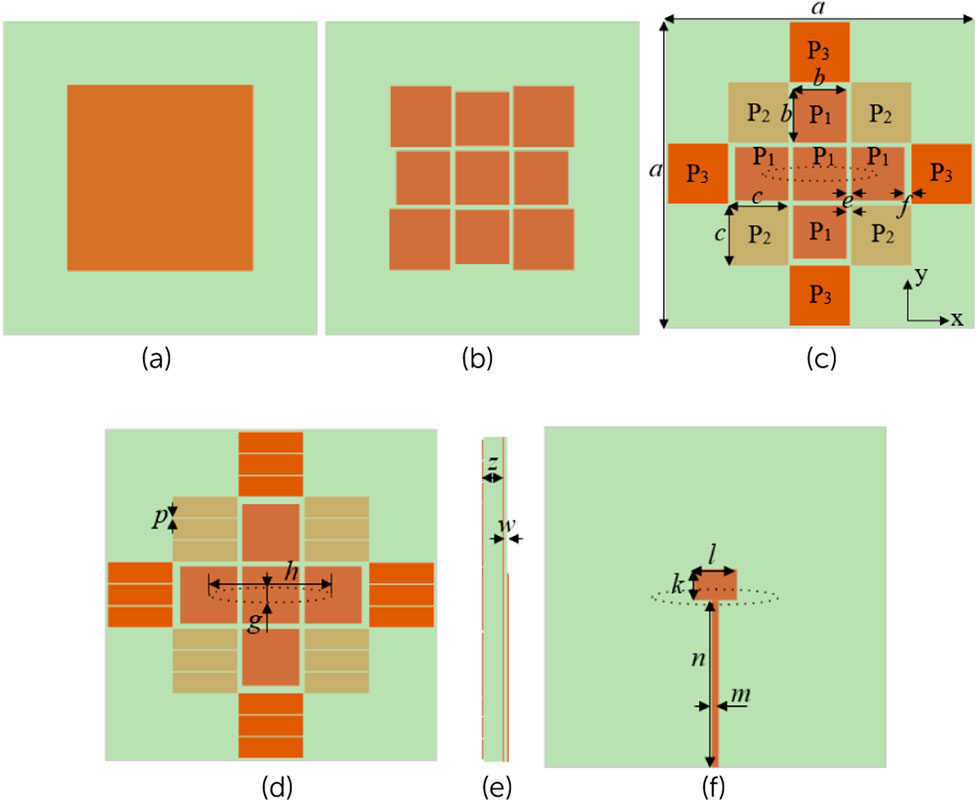
Figure 1. Geometry of the proposed antenna: (a) type I, (b) type II, (c) type III, (d) type IV, (e) side view, and (f) bottom view.
Types I–Ⅳ are fed by a microstrip line at the bottom through an ellipse slot etched on the middle ground plane, as shown in Figure 1f. The corresponding antennas are named antennas I–Ⅳ, respectively. The dielectric substrate is Rogers RO4003C with a relative permittivity of 3.55 and a loss tangent of 0.0027, and the thicknesses are 3.454 mm and 0.508 mm, respectively. The dimensions of the antenna are listed in Table 1.
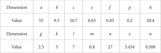
Table 1. Structure parameters of the antenna (units: mm).
2.1 Effect of the parasitic patches on the bandwidth
To illustrate the effect of the 3 × 3 patches and the four parasitic patches P3 on the performance of the bandwidth, the counterparts of types I–II are compared to that of type III, respectively. The simulated analysis is carried out using CST Microwave Studio.
According to the theory of characteristic modes [2–4], modal significance (MS) indicates the degree to which each characteristic mode is easily excited, which is only determined by the MTS structure. When MS = 1, the mode is easily excited, whereas MS = 0 means that the mode hardly resonates or radiates. The CMA is performed on types I–III without the feeding structure for identifying the potential bandwidth (MS > 0.7) of the modes. By optimizing the design of both the MTS and the antenna, it is possible to fully utilize the potential bandwidth of the MTS, thereby significantly expanding the impedance bandwidth of the antenna. Figure 2 shows the MS curve, characteristic currents, and radiation patterns of modes J1–J6 for types I–III. Figures 2a–c demonstrate that several MSs are greater than 0.7 and range from 4 to 8 GHz, which means that these modes may be excited effectively. For type I in Figure 2a, the modes have a narrow resonant frequency band compared with the modes of types II and III in Figures 2b, c. Furthermore, none of the modes in Figure 2a can be excited to realize the broadside radiation pattern because of the out-of-phase current distribution. For type II in Figure 2b, the potential bandwidths of the degenerate modes J1 and J2 are 4.8 GHz–6.75 GHz. In addition, the corresponding currents of J1 and J2 are oriented in the same direction, and only one main lobe is observed, indicating that J1 and J2 are the fundamental modes in the target frequency band. The HOMs J3–J6 have radiation nulls in the boresight direction because of the out-of-phase current distribution. The same situation also exists in type III (Figure 2c), but the fundamental mode J1 of type III has a broader potential bandwidth of 4.7 GHz–6.75 GHz compared with that of type II (4.8 GHz–6.75 GHz) in Figure 2b. In other words, it is easier to obtain a broader bandwidth with antenna III than with antenna II.
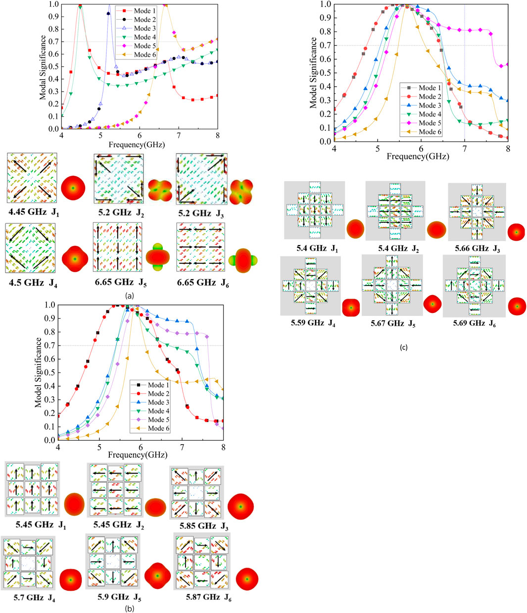
Figure 2. MSs, characteristic currents, and the radiation patterns of the three MTS structures: (a) type I, (b) type II, and (c) type III.
Subsequently, the reflection coefficient of the antennas Ⅰ–Ⅲ are simulated and shown in Figure 3. For antenna Ⅰ, there are two independent resonances at 5.18 GHz and 6.4 GHz, and the bandwidth is narrow. For antenna II, the resonances appear at 4.6 GHz, 5.9 GHz, and 6.8 GHz. However, these three resonances are separated from each other. For antenna III, there are four resonances at 4.8 GHz, 6 GHz, 6.5 GHz, and 7 GHz, respectively. The several resonant frequencies combine with each other, and the impedance bandwidth of approximately 50.2% (4.47–7.47 GHz) is obtained.
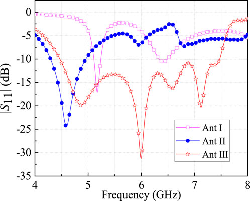
Figure 3. Simulated |S11| of the antennas I–III.
Subsequently, the realized gain of antenna III is simulated and shown in Figure 4a. As shown, the realized gain range of −1.17–5.5 dBi in the high-frequency band of 6.5 GHz–7.5 GHz is significantly lower than that of 7.2–9.7 dBi in the low-frequency band of 4.5 GHz–6 GHz. Specifically at 7 GHz, the realized gain is only −1.17 dBi. To investigate this, the surface current distribution of antenna III at 7 GHz is simulated and shown in Figure 4b. The currents on the patches P1 are out-of-phase with those on patches P2 and P3. Consequently, the realized gain decreases at 7 GHz as the radiation caused by the out-of-phase currents is largely canceled in the boresight direction.
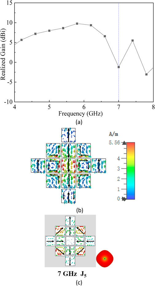
Figure 4. Simulated results of antenna III: (a) realized gain, (b) surface currents at 7 GHz, and (c) the modal current and radiation patterns of J5 at 7 GHz.
To illustrate the design concept of improving the radiation performance of antenna III at high frequency using CMA, the mode behavior for type III needs to be reanalyzed. In Figure 2c, mode J5 resonates at 5.67 GHz and exhibits radiation nulls in the boresight direction; however, it is heavily excited at 7 GHz. According to the theory of CMA, modal currents change with the frequency [3]. Therefore, the modal current and radiation patterns of J5 at 7 GHz are simulated and shown in Figure 4c. There is a radiation null in the broadside direction of J5 at 7 GHz, which will lead to a reduction in the realized gain at 7 GHz. Due to the large out-of-phase currents of J5 at the P2 and P3 locations, loading two slots along the x-axis at P2 and P3 can interrupt the out-of-phase currents and suppress the unwanted HOM J5 without affecting the fundamental mode J1, whose maximum current distribution is located at P1. The optimized MTS is named type Ⅳ, and the mode behavior and the effect on the realized gain are analyzed in Section 2.2.
2.2 Effect of the slots along the x-axis on the radiation performance
The MSs, modal currents, and radiation patterns for type Ⅳ are shown in Figure 5. The subscript “s” represents the loading slot. In Figure 5a, the MSs of Js1–Js5 are greater than 0.7, ranging from 4.7 to above 7.17 GHz. Furthermore, a new mode Js6 appears with a resonant frequency of 7.94 GHz. In Figure 5b, by loading two slots at P2 and P3 along the x-axis, the out-of-phase characteristic currents are interrupted, and the radiation nulls of most of the HOMs are eliminated. Therefore, the radiation patterns of the optimized modes Js4, Js5, and Js6 are broadside. Although the radiation patterns of Js2 and Js3 have large sidelobes, the maximum currents of these two modes are distributed in P2 and P3. Therefore, modes Js2 and Js3 are difficult to excite by the ellipse slot etched at the center of the ground plane. On the contrary, modes Js1, Js4, and Js6, which have broadside radiation patterns, can easily be excited because their maximum currents are distributed in P1. Next, we focus on the mode behavior of 7 GHz. As shown in Figure 5a, the MS of mode Js5 is approximately 0.83 at 7 GHz, which is much larger than that of any other modes. Hence, the modal current and the radiation pattern of Js5 at 7 GHz are analyzed and shown in Figure 5c. Unlike the mode J5 of type III in Figure 4c, the radiation pattern of Js5 at 7 GHz is broadside, and the maximum currents are primarily distributed at P1. Therefore, the ellipse slot etched at the center of the ground plane can effectively excite mode Js5, which helps the proposed antenna to achieve high realized gain at 7 GHz. Meanwhile, the potential bandwidth of these broadside radiation modes Js1, Js4 Js5, and Js6 extends from 4.7 GHz to approximately 9 GHz (Figure 5a), which helps the proposed antenna achieve higher realized gain across the entire operating frequency band.
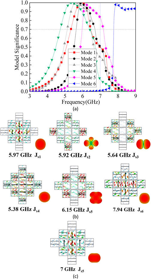
Figure 5. Modes of the type IV: (a) MS, (b) characteristic currents and the radiation patterns at resonant frequencies, and (c) mode current and the radiation pattern of Js5 at 7 GHz.
The surface currents of the proposed antenna Ⅳ at 7 GHz are investigated and shown in Figure 6. It is clear that this current distribution is well-consistent with the current of mode Js5 at 7 GHz shown in Figure 5c, which illustrates that the optimized mode Js5 is well-excited by the proposed feeding structure at 7 GHz.
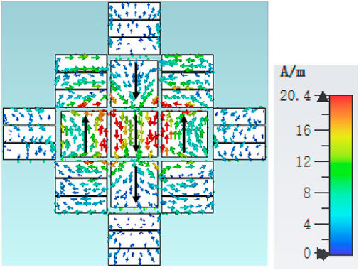
Figure 6. Simulated surface currents of antenna IV at 7 GHz.
To prove that type Ⅳ is effective in improving the realized gain at 7 GHz, the simulated radiation patterns of antennas Ⅲ and Ⅳ at 7 GHz are also investigated and shown in Figure 7. Compared to antenna Ⅲ, the main lobe magnitude of antenna Ⅳ at 7 GHz is enhanced from −1.17 dBi to 9.56 dBi.
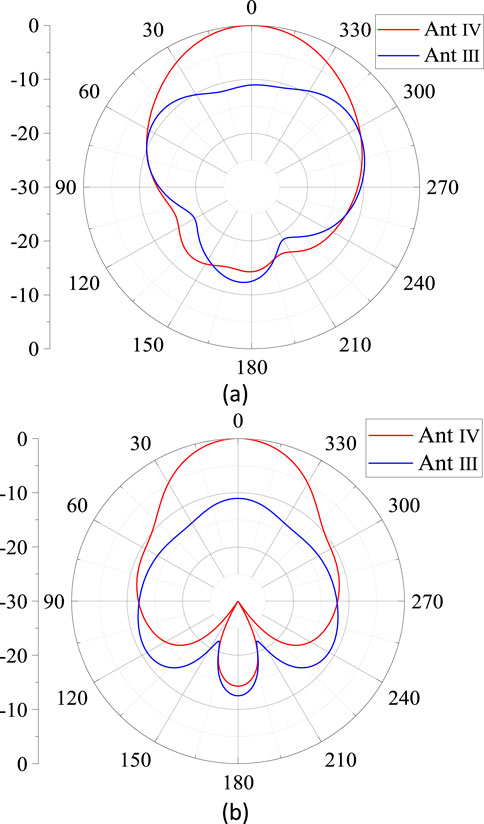
Figure 7. Simulated normalized radiation patterns of antennas III and IV at 7 GHz: (a) E-plane and (b) H-plane.
Subsequently, the simulated |S11| and realized gain of antennas Ⅲ and Ⅳ are investigated and shown in Figure 8. Antenna Ⅲ achieves a gain range of −1.17–5.5 dBi in the high-frequency band of 6.5 GHz–7.5 GHz, which is significantly lower than the gain of 7.4–9.4 dBi in the low-frequency band of 4.5 GHz–6 GHz. However, the modified antenna Ⅳ can operate from 4.7 to 8.36 GHz with a flat gain of 7–10 dBi. Specifically, the realized gain at 7 GHz is enhanced from −1.17 dBi to 9.5 dBi due to the slots along the x-axis for mode optimization. It indicates that the proposed antenna Ⅳ is effective in optimizing the radiation performance at a high operating band.
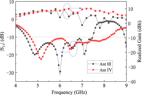
Figure 8. Simulated |S11| and the realized gain of the antennas III and IV.
3 Measured results and discussions
The photograph of the fabricated antenna Ⅳ is shown in Figure 9. The fabrication tolerance of copper foil is 0.015 mm. The magnitude of |S11| is measured using a network analyzer (Agilent N5230C). The radiation patterns are measured in an anechoic chamber using the antenna test arrangement shown in Figure 10. Figure 11 shows the simulated and measured S-parameters and realized gain of the proposed antenna. It can be observed that the proposed MTS antenna operates in the frequency band of 4.66–8.22 GHz (|S11|< −10 dB) with a relative bandwidth of 55.2% and a flat realized gain of 7–10 dBi. The measured result agrees well with the simulated result. We can also find that the measured result of |S11| is slightly better than the simulated result. This may result from the slight increase in thickness in the hot-pressing process.
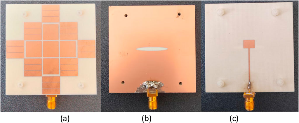
Figure 9. Photograph of the antenna: (a) top, (b) ground, and (c) bottom.
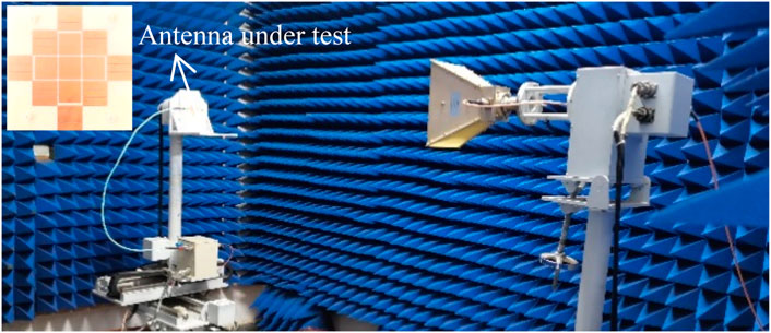
Figure 10. Photograph of the antenna measurement set-up.
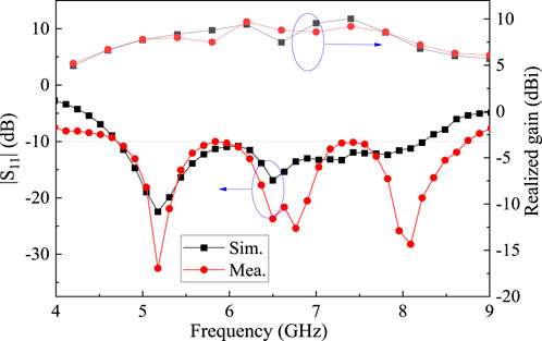
Figure 11. Simulated and measured S-parameters and realized gain.
The normalized radiation patterns at different frequencies are shown in Figure 12. It can be observed that the measured results agree with the simulated results.
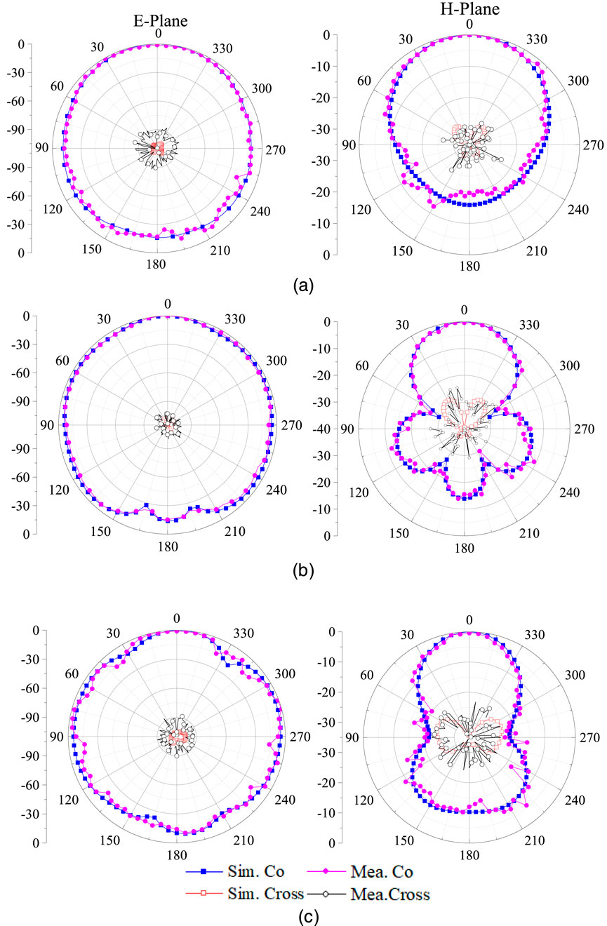
Figure 12. Simulated and measured radiation patterns: (a) 5 GHz, (b) 6.5 GHz, and (c) 8 GHz.
Table 2 shows the comparison of the performances of the proposed MTS antenna and previously reported linear polarization MTS antennas. The proposed antenna achieves the widest bandwidth compared with the references in Table 2. Compared with the relative reported works [11, 15], the proposed antenna has excellent performance, including broader bandwidth and larger gain. Compared with the related works [7, 20], the proposed antenna has a higher bandwidth and a higher minimum gain, although its peak gain is slightly lower.
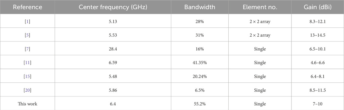
Table 2. Comparison with reported linear polarization MTS antennas and arrays.
4 Conclusion
A high-frequency gain enhancement of a broadband MTS antenna with parasitic patches using CMA was proposed. Four parasitic patches around the 3 × 3 squared patches on the MTS help the proposed antenna to achieve a broad bandwidth. Two slots along the x-axis are introduced in part of the MTS unit cells for improving the antenna radiation performance at a high operating band using CMA. The proposed antenna realizes a 55.2% (4.66 GHz–8.22 GHz) impedance bandwidth for |S11| ≤ −10 dB and maintains a flat gain of 7–10 dBi. In addition, the proposed MTS antenna offers cost-effective implementation and easy integration with the planar circuits due to its fully planar structure and low profile.
Data availability statement
The original contributions presented in the study are included in the article/supplementary material, further inquiries can be directed to the corresponding author.
Author contributions
HL: Validation, Writing – review and editing, Data curation, Writing – original draft. ZY: Data curation, Writing – review and editing. YGa: Writing – review and editing, Validation. LD: Writing – review and editing. YGu: Writing – review and editing, Data curation. XX: Validation, Writing – review and editing. TM: Data curation, Writing – review and editing. WH: Writing – review and editing, Validation. CF: Writing – original draft, Writing – review and editing, Validation.
Funding
The author(s) declare that financial support was received for the research and/or publication of this article. This work was supported by the Natural Science Foundation of Shanxi Province, China (202303021211182), the Science and Technology Innovation Program of Institutions of Higher Education of Shanxi Province, China (2023L258), the Central Government Guides Local Science and Technology Development Funds (YDZJSX2021B011), the Applied Basic Research Projects of Shanxi Province, China (202203021221212), the Platform Program of Datong (2023086), the Applied Basic Research Projects of DaTong, China (2023066), and the Basic Research Fund Project of Shanxi Datong University, China (2022K6). The authors thank Shanxi Key Laboratory of Wireless Communication and Detection, Shanxi University, for providing antenna far-field testing services.
Conflict of interest
The authors declare that the research was conducted in the absence of any commercial or financial relationships that could be construed as a potential conflict of interest.
Generative AI statement
The author(s) declare that no Generative AI was used in the creation of this manuscript.
Publisher’s note
All claims expressed in this article are solely those of the authors and do not necessarily represent those of their affiliated organizations, or those of the publisher, the editors and the reviewers. Any product that may be evaluated in this article, or claim that may be made by its manufacturer, is not guaranteed or endorsed by the publisher.
References
1. Nie NS, Yang XS, Chen ZN, Wang BZ. A low-profile wideband hybrid metasurface antenna array for 5g and wifi systems. IEEE Trans Antennas Propagation (2020) 68(2):665–71. doi:10.1109/TAP.2019.2940367
2. Harrington R, Mautz J. Computation of characteristic modes for conducting bodies. IEEE Trans Antennas Propagation (1971) 19(5):629–39. doi:10.1109/TAP.1971.1139990
3. Harrington R, Mautz J. Theory of characteristic modes for conducting bodies. IEEE Trans Antennas Propagation (1971) 19(5):622–8. doi:10.1109/TAP.1971.1139999
4. Cabedo-Fabres M, Antonino-Daviu E, Valero-Nogueira A, Bataller MF. The theory of characteristic modes revisited: a contribution to the design of antennas for modern applications. IEEE Antennas Propagation Mag (2007) 49(5):52–68. doi:10.1109/MAP.2007.4395295
5. Lin FH, Chen ZN. Low-profile wideband metasurface antennas using characteristic mode analysis. IEEE Trans Antennas Propagation (2017) 65(4):1706–13. doi:10.1109/TAP.2017.2671036
6. Lin FH, Chen ZN. A method of suppressing higher order modes for improving radiation performance of metasurface multiport antennas using characteristic mode analysis. IEEE Trans Antennas Propagation (2018) 66(4):1894–902. doi:10.1109/TAP.2018.2806401
7. Xue M, Wan W, Wang Q, Cao L. Low-profile millimeter-wave broadband metasurface antenna with four resonances. IEEE Antennas Wireless Propagation Lett (2021) 20(4):463–7. doi:10.1109/LAWP.2021.3053589
8. Ntawangaheza JD, Sun L, Xie Z, Pang Y, Zheng Z, Rushingabigwi G. A single-layer low-profile broadband metasurface antenna array for sub-6 Ghz 5g communication systems. IEEE Trans Antennas Propagation (2021) 69(4):2061–71. doi:10.1109/TAP.2020.3027042
9. J Yu, and H Li, editors Characteristic mode aided design of handset antennas with high isolations. IEEE International Symposium On Antennas And Propagation ISAP (2023).
10. YZ Deng, N Yang, K Lu, and J Nan, editors Characteristic mode cancellation for radiation pattern decoupling of asymmetric dipole antennas. 2024 cross strait radio science and wireless Technology conference (CSRSWTC) (2024).
11. Chen D, Yang W, Xue Q, Che W. Miniaturized wideband planar antenna using interembedded metasurface structure. IEEE Trans Antennas Propagation (2021) 69(5):3021–6. doi:10.1109/TAP.2020.3028245
12. Yang W, Huang J, Chen D, Yu KL, Xue Q, Che W. Broadband dual-polarized filtering metasurface-based antennas using characteristic mode analysis for 5g millimeter-wave applications. IEEE Trans Antennas Propagation (2024) 72(5):3912–27. doi:10.1109/TAP.2024.3377918
13. Wu D, Sun YX, Lian R, Xiao B, Li M, Xu KD. Metasurface antenna with cocircularly polarized radiation characteristics for wideband monostatic simultaneous transmit and receive applications. IEEE Trans Antennas Propagation (2023) 71(4):3304–13. doi:10.1109/TAP.2023.3243988
14. Lin FH, Chen ZN. Resonant metasurface antennas with resonant apertures: characteristic mode analysis and dual-polarized broadband low-profile design. IEEE Trans Antennas Propagation (2021) 69(6):3512–6. doi:10.1109/TAP.2020.3028246
15. Liu J, Weng Z, Zhang ZQ, Qiu Y, Zhang YX, Jiao YC. A wideband pattern diversity antenna with a low profile based on metasurface. IEEE Antennas Wireless Propagation Lett (2021) 20(3):303–7. doi:10.1109/LAWP.2020.3048633
16. L Han, Z Li, G Han, and W Zhang, editors Wideband metasurface antenna using characteristic mode analysis. 2021 international conference on Microwave and millimeter wave Technology (ICMMT) (2021).
17. Liu P, Jiang W, Sun S, Xi Y, Gong S. Broadband and low-profile penta-polarization reconfigurable metamaterial antenna. IEEE Access (2020) 8:21823–31. doi:10.1109/ACCESS.2020.2969488
18. Naik DK, Panda DC, Swain R, Muduli A, Nanda S. Pac-man-shaped patch-driven broadband circularly polarized metasurface antenna with cma-based quadruple-mode excitation. IEEE Access (2025) 13:13644–54. doi:10.1109/ACCESS.2025.3526682
19. Zhang P, Zhang W, Chen X, Han G, Su J, Yang R. Low-sidelobe dual-beam antenna based on metasurface with independently regulated amplitude/phase. IEEE Antennas Wireless Propagation Lett (2023) 22(10):2382–6. doi:10.1109/LAWP.2023.3288601
20. Wang K, Shao W, Ding X, Wang BZ, Jiang B. Design of high-gain metasurface antenna based on characteristic mode analysis. IEEE Antennas Wireless Propagation Lett (2022) 21(4):661–5. doi:10.1109/LAWP.2022.3140326
21. Luo Y, Zhu L, Liu Y, Xu Y, Liu N, Gong S. Efficiency improvement of smartphone antennas using higher-order mode suppression under characteristic mode analysis. IEEE Trans Antennas Propagation (2022) 70(11):10304–17. doi:10.1109/TAP.2022.3195537
Keywords: broadband, characteristic mode analysis, metasurface, parasitic patches, flat gain
Citation: Liu H, Yang Z, Gao Y, Dong L, Guo Y, Xu X, Meng T, Hu W and Feng C (2025) High-frequency gain enhancement of a broadband metasurface antenna with parasitic patches using characteristic mode analysis. Front. Phys. 13:1638385. doi: 10.3389/fphy.2025.1638385
Received: 30 May 2025; Accepted: 30 June 2025;
Published: 21 July 2025.
Edited by:
Xukun Yin, Xidian University, ChinaReviewed by:
Xinwei Chen, Shanxi University, ChinaYongqing Leng, Institute of Microelectronics of the Chinese Academy of Sciences, China
Copyright © 2025 Liu, Yang, Gao, Dong, Guo, Xu, Meng, Hu and Feng. This is an open-access article distributed under the terms of the Creative Commons Attribution License (CC BY). The use, distribution or reproduction in other forums is permitted, provided the original author(s) and the copyright owner(s) are credited and that the original publication in this journal is cited, in accordance with accepted academic practice. No use, distribution or reproduction is permitted which does not comply with these terms.
*Correspondence: Caixia Feng, ZmN4ZHRkeEAxNjMuY29t