 Limin Hu1
 Yingying Hu
 Yan Shi
- 1Hangzhou Hpwinner Opto Corporation, Hangzhou, China
- 2China Jiliang University, Hangzhou, China
- 3Hefei Low-carbon Institute, Hefei, China
With the increasing adoption of LEDs in plant lighting applications, reducing costs and enhancing light efficiency have emerged as key research priorities in this domain. Currently, light-emitting modules in LED plant lighting systems predominantly employ ceramic packaging, with PLCC packaging being seldom utilized due to its lower light extraction efficiency. This study introduces a novel approach by incorporating both planar optical encapsulant and the filler material in the assembly of red light chips, achieving a 22% improvement in light efficiency. By addressing this technical limitation, the design effectively reduces costs, resulting in a cost-effective light-emitting module with high light extraction performance. Furthermore, the design was tested with multiple chips, demonstrating significant potential for further optimization and advanced design applications.
1 Introduction
Ecological agriculture’s rise defines the current era, where physical agriculture enables sustainable agricultural systems [1]. Within this framework, optical technology holds significant importance, as light is a critical component of agricultural ecosystems. Light quality, intensity, and photoperiod critically regulate plant growth and development. Optimal light exposure enhances photosynthetic activity, leading to improved crop quality and yield. Historically, traditional light sources like fluorescent lamps, incandescent lamps, and high-pressure sodium lamps (HPS) have been utilized in agriculture [2]. However, they suffer from low efficiency, high energy consumption, and ineffective wavelengths for plant growth. Furthermore, excessive heat generation from some sources restricts their ability to provide close-range illumination. Recent advancements in optoelectronic technology have enabled the adoption of light-emitting diodes (LEDs) in agriculture, owing to their superior light efficiency, tunable spectra, and long operational lifespan. These features position LEDs as a sustainable and energy-efficient lighting solution for modern agricultural practices.
The 1990s witnessed significant progress in artificial lighting technology. Groundbreaking research by the University of Wisconsin, Purdue University, and NASA’s Kennedy Space Center pioneered the application of LED technology in plant science, specifically examining its impact on plant growth [3]. As shown in Figure 1 LEDs enable precise alignment of light wavelengths with plant photoreceptors, thereby optimizing metabolic processes and improving productivity. From the 1990s to the early 2020s, extensive studies investigated the effects of monochromatic and polychromatic LED light spectra on diverse plant species, uncovering notable changes in morphology and physiology [4]. For example, in 2005 von Wettberg reported that red light could regulate branch elongation in woody plants [5]. In 2013, studies further elucidated the effects of red, blue, and white light of different spectral qualities on plant biomass and leaf chlorophyll content [6].
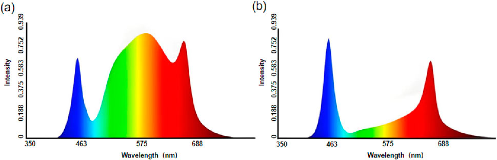
Figure 1. (a) A spectral configuration optimized for heliophilic plants, such as industrial hemp and tomatoes; (b) A spectral configuration tailored for applications in seedling propagation, plant breeding, and tissue culture experiments.
The use of LED fixtures in plant lighting has seen significant expansion. Through advanced packaging technologies, LED chips are strategically arranged on substrates and can be driven either regionally or individually. Advanced controls permit precise adjustments for plant growth stages and external light, meeting diverse lighting demandss [7]. Today, LED fixtures are widely employed in areas such as greenhouse supplemental lighting [8], field supplemental lighting [9], and transplant production [10].
Packaging materials are pivotal in influencing LED performance. Materials with high refractive indices, UV/thermal resistance, and low stress enhance LED light output efficiency and lifespan. The inception of LEDs dates back to the 1950s, when British scientists created the first LED using gallium arsenide semiconductors in electroluminescence experiments. By the 1960s, LEDs had entered the commercial market, although the initial versions were limited to visible light and could not emit infrared. Despite this, they found widespread applications. Early packaging methods relied on a free dispensing coating process, which frequently caused yellow rings in the phosphor mixed adhesive layer, with only incremental improvements available [11]. In 2005, Fujita’s research group made a groundbreaking advancement by studying Ce 3+:YAG glass-ceramics, which brought ceramic packaging technology to the forefront [12]. This innovation catalyzed extensive research into diverse glass-ceramic materials. Today, red light chips in LED plant lighting modules predominantly employ ceramic packaging, while the Plastic Leaded Chip Carrier (PLCC) method is less frequently used. PLCC packaging, an evolution of COB technology, is also known as the cover module packaging mode. However, ceramic packaging involves complex manufacturing processes with inherently higher material costs. In contrast, PLCC’s plastic-based architecture enables simpler production, projecting potential cost advantages based on structural and material analysis. Final cost-effectiveness requires further validation through scalable manufacturing. Ceramic packaging typically requires the integration of a dome structure on the chip [13]. When red light chips are encapsulated using ceramic packaging, the emitted light is less susceptible to total reflection upon reaching the dome surface. In contrast, if the same red light chip is packaged using the PLCC method, although the cost is lower, the light extraction efficiency of the PLCC device is significantly compromised. This is due to the presence of the optical encapsulant on the front side of the PLCC package, which has a flat surface. Light from red chips strikes flat PLCC surfaces with high total reflection risk, reducing Photosynthetic Photon Efficacy (PPE) and compromising plant-growth enhancement. This study implements filler material between lens and light-emitting component in PLCC-packaged red LEDs, eliminating air gaps to suppress total reflection. The synergistic optimization of filler, encapsulant, and lens enhances light distribution, improving extraction efficiency by 22%. This maintains high PPE with cost-effective PLCC packaging, enabling broader horticultural applications.
2 Research methodology
The designed light-emitting module consists of a substrate part, a lens part, and a light-emitting component. As shown in Figure 2a, the light-emitting component is mounted on the substrate, with the lens plate positioned above it and connected to the substrate. The lens part is designed with lenses corresponding to the light-emitting component. The light-emitting component is a PLCC-packaged red light device, which includes a bracket and a red light chip encapsulated with optical encapsulant, where the side facing the lens plate is flat. Notably, optical encapsulant has been added between the lens and the light-emitting component. The filler material integrates the device and the lens into a cohesive unit, minimizing internal light deflection and loss, thereby achieving efficient light distribution in a single step. Additionally, it enhances the extraction efficiency of red light photons emitted by the light-emitting component.
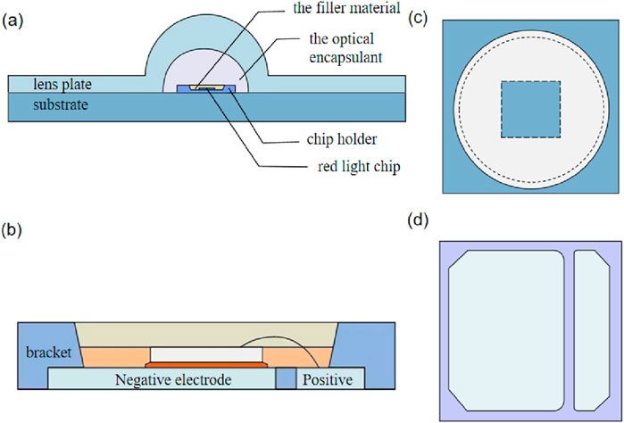
Figure 2. Illustrates the optical module design: (a) overall structure of the light-emitting module, (b) structure of the light-emitting component, (c) top view of the light-emitting component, and (d) bottom view of the light-emitting component.
As illustrated in Figure 2b, within the light-emitting component, the red light chip is connected to the positive and negative conductive metals via die attach adhesive and wires. The conductive metal, made of silver-plated copper sheets, provides both electrical conductivity and thermal dissipation. Figures 2c, d show the other side of the design.
The red LED chip employs vertical packaging. Horizontal packaging positions both p/n electrodes on the same chip side, causing current crowding [14]. Furthermore, the low thermal conductivity of the sapphire substrate in horizontal structures significantly hinders heat dissipation from the chip. Prolonged operation under high temperatures due to poor heat dissipation can degrade the performance and transmittance of the filler material, leading to substantial light output power loss. Studies have demonstrated that vertical structures significantly reduce ideality factors and series resistance with better heat dissipation performance [15, 16]. The vertical packaging structure achieves excellent current diffusion by replacing the sapphire substrate with a high thermal conductivity substrate (such as Si, Ge or Cu), thereby significantly improving the heat dissipation efficiency. Additionally, in the vertical structure, the two electrodes are positioned on opposite sides of the LED epitaxial layer. This configuration enables near-vertical current flow with negligible lateral currents, eliminating localized heating while boosting heat dissipation efficiency [17]. Consequently, vertical packaging delivers superior thermal management, improved luminous efficiency, and extended operational lifespan.
A reflective coating has been applied to the inner surface of the recessed portion of the bracket to enhance light reflection. In this design, a diffuse reflection coating is utilized to significantly improve luminous flux. The coating ensures that light emitted by the red light chip towards the bracket side is either reflected or totally reflected, then redirected towards the lens side as effective light, thereby substantially enhancing light extraction efficiency. Additionally, a high-reflectivity silver layer or other coatings, including mixed layers achieving both specular and diffuse reflection, can be employed to achieve specific optical effects.
The selected commercial filler material possesses a refractive index of 1.42 and demonstrates stable optical transmittance across its operational range of −20 °C–120 °C. Crucially, it exhibits no detectable thermal degradation at 65 °C, confirming robust stability under operational conditions [18]. The filler material comprises two layers, with silicon dioxide doped into the lower layer to increase reflectivity while maintaining the refractive index, further improving light extraction efficiency. Notably, current filler stability verification relies on short-term tests within defined temperature ranges. Actual applications involve prolonged thermal cycling, where sustained stress may cause gradual degradation of optical and thermal properties even after initial stability confirmation. This degradation impacts long-term device reliability, including luminous efficiency and lifespan.
We will implement systematic long-term thermal reliability validation for filler materials in subsequent phases. This work will track performance evolution under extended thermal exposure, providing practical data for material optimization. Our ongoing focus will monitor how these materials maintain stability during sustained operation, forming a key consideration for future industrial applications.
As shown in Figure 3, three types of light-emitting modules are currently prevalent in the industry. The PLCC-packaged light source device without a dome incorporates a PLCC-packaged red light chip and a lens. The main optical path is: red light emitted by the chip → planar optical encapsulant → air → lens part. At the interface between the optical encapsulant and air, total reflection and Fresnel reflection result in an estimated loss exceeding 18%. An additional 4% loss occurs due to Fresnel reflection at the lens interface. Consequently, such devices exhibit low light extraction efficiency and limited applicability.
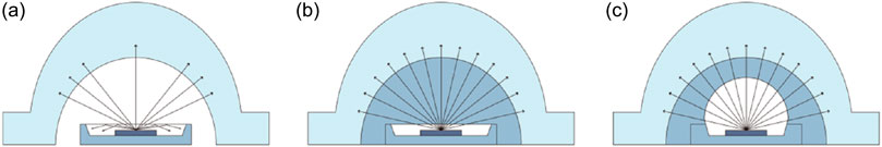
Figure 3. Depicts three types of light-emitting modules: (a) a PLCC-packaged light source device without a dome, (b) a PLCC dispensing light source device without a dome, and (c) a dispensing light source device with a dome.
In the PLCC dispensing light source device without a dome, white light chips are used instead of red light chips to improve light extraction efficiency, as the latter demonstrated poor performance. Filler material is added between the lens and the chip. The main optical path is: white light emitted by the chip → optical encapsulant → filler material → lens part. Due to the similar refractive indices of the optical encapsulant, filler material, and lens part, optical losses are reduced, but the improvement in light extraction efficiency is only approximately 8%. This indicates that the effects of white light and filler material are marginal.
In the dispensing light source device with a dome, a dome structure is introduced. The main optical path is: light emitted by the chip → dome → filler material → lens part. Although the dome significantly increases costs, the improvement in light extraction efficiency remains modest, at around 8%.
From these observations, it is evident that the addition of filler material provides only limited improvements in light extraction efficiency, regardless of whether white or red light sources are used or whether a dome is present. Given that filler material has a minimal impact on white light chips, its effect on red light chips, which inherently exhibit inferior light emission, is even less pronounced. Our design overcomes technical biases by strategically integrating both planar optical encapsulant and filler material in PLCC-packaged red light chips without a dome. This approach reduces or eliminates total reflection and optimizes light distribution through the combined use of planar optical encapsulant, filler material, and lens, thereby significantly enhancing light extraction efficiency. In summary, we have developed a cost-effective light-emitting module with superior light extraction performance.
3 Experimental design and methodology
3.1 Calculation of light efficacy metrics
In practical design, the refractive indices of the various components within the LED module can be tuned across a broad range. The refractive index of the filler material is slightly lower than that of the optical encapsulant, and reducing the difference between their refractive indices can minimize total reflection. Conversely, if the refractive index of the filler material is slightly higher than that of the optical encapsulant, total reflection can be entirely eliminated. Ideally, the refractive indices of the filler material and optical encapsulant should be equal; however, achieving this in practice is challenging. Therefore, in manufacturing, a filler material with a refractive index slightly higher than that of the optical encapsulant is typically selected.
In this design, the LED red light chip is fabricated from a material with a refractive index of 2.9. The optical encapsulant has a refractive index of 1.528, the filling material has a refractive index of 1.42, and the lens part has a refractive index of 1.59. This selection was determined through comprehensive consideration of ray-tracing simulation results, material costs, and key properties. Preliminary ray-tracing simulations were conducted to predict the light extraction efficiency of the LED module across filler materials with refractive indices of 1.40, 1.42, 1.44, 1.46, and 1.48. Analysis revealed that the efficiency at RI = 1.40 was lower than 1.42, accounting for an 8.3% reduction in photons captured due to total internal reflection. This observation aligns with the Fresnel equations, indicating that reduced RI differences minimize interfacial reflection losses. However, as the filler RI increases and approaches that of the optical encapsulation material, light scattering phenomena at the filler-lens interface become significantly more pronounced. Furthermore, material stability, cost, and manufacturability were integral to the evaluation. Based on the limited material options and comparative experimental data, the filler material with an RI of 1.42 was identified as the optimal choice, delivering the optimal balance between high LEE, output uniformity, and practical material constraints.
We will analyze the influence of optical encapsulants and filling materials on the luminous flux of the LED module. For this analysis, the upper surface of the LED red light chip is assumed to be the light-emitting surface, with the light intensity distribution following a Lambertian profile. The peak light intensity of the LED chip is
Figure 4 depicts the coordinate system and angular parameters used to calculate the luminous flux of a light source exhibiting a Lambertian intensity distribution. In this figure, S represents the light source,
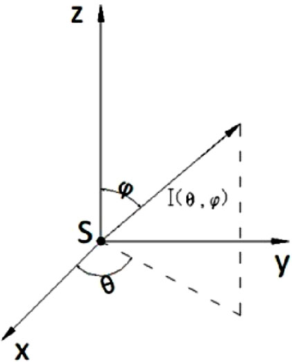
Figure 4. Schematic illustration of the principles underlying luminous flux calculation.
Substituting the relevant parameters into Equations 1–3, we obtain:
The critical angle
In Equation 6,
By substituting the experimental data, the luminous flux of the light-emitting component
When a lens is incorporated, the emitted light experiences reflection losses at both the air-lens and lens-air interfaces, as well as absorption losses within the lens. The reflectance ratios for the two reflections are given by:
Substituting the data, the calculated loss rates are 4.4% at the air-lens interface and 1.3% due to absorption within the lens. The final luminous flux is expressed as:
In the case where filler material and a lens are added to the light-emitting component, the luminous flux is calculated using the same formula as Equation 5, but with a different critical angle for total reflection. The critical angle
The resulting luminous flux of the light-emitting component
At these interfaces, the light undergoes additional Fresnel reflection losses. For simplicity, we assume that the light is nearly perpendicular to these interfaces, and the reflection losses are calculated using Equation 7. Additionally, the absorption of light as it traverses the optical encapsulant, filler material, and lens must be accounted for. Based on our analysis, the combined reflection and absorption losses amount to 7.2%.
Consequently, the luminous flux of the light-emitting component, with the inclusion of filler material and a lens,
However, in practice, the recessed portion of the light-emitting component’s bracket is coated with a reflective layer, which exhibits an overall reflectance of 40% for light that is either reflected or totally reflected. Therefore, the total luminous flux of the light-emitting component is 1.98
From the theoretical calculations and analysis presented above, it is evident that the light source emits 3.14
3.2 Experimental test data
Using 18PCS of 5050 55mil red light chips as an example, we further demonstrate the light efficiency outcomes under three scenarios: 1-without a lens, 2-with a lens, and 3-with both a lens and filler material.
As illustrated in Figure 5, the luminous flux, PPF, and PPE values are higher when both filler material and a lens are used compared to using only a lens without filler material, indicating superior light efficiency. Furthermore, as power increases, the configuration incorporating both a lens and filler material exhibits a more pronounced improvement rate.
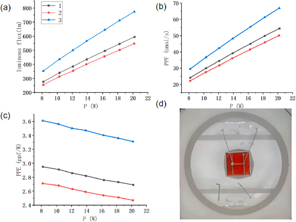
Figure 5. (a) Luminous flux under three conditions; (b) Photosynthetic photon flux (PPF) under three conditions; (c) PPE under three conditions; (d) Schematic of the red light chip.
As illustrated in Figure 6, photoelectronic characterization across 300–800 nm verifies this luminaire as a spectrally tailored horticultural lighting system optimized for fruiting-crop flowering. The 600–700 nm band dominates PPF contribution (77%; 408.9/531.6 μ·mol·s-1), confirming precise alignment with chlorophyll absorption maxima. Significantly, 95.7% white-light-referenced electro-optical conversion efficiency demonstrates exceptional energy utilization. These collective findings validate the robustness of our encapsulation methodology within this spectral regime.
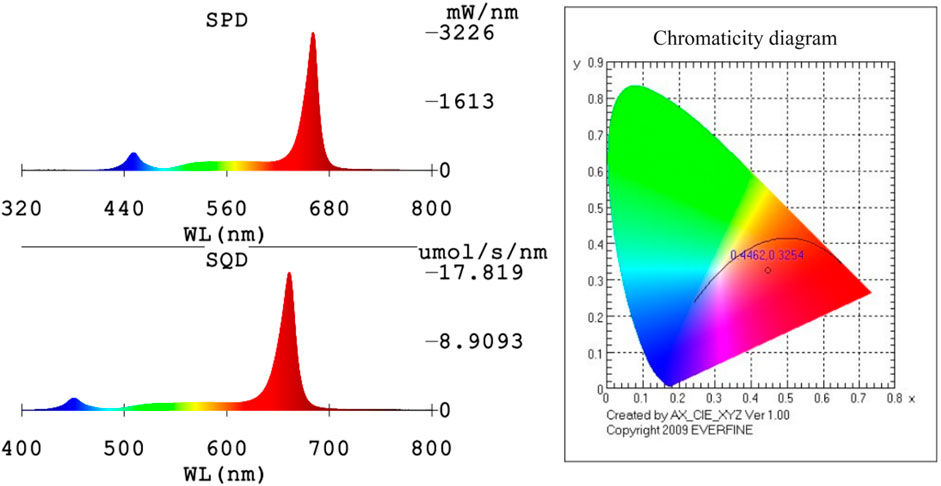
Figure 6. Photoelectric detection diagram.
Ceramic encapsulation faces challenges in bracket design and manufacturing for multi-chip packaging of small LEDs, increasing costs. Consequently, it is better suited for single red-light chips. Employing multiple red-light chips represents a common strategy to enhance photosynthetic photon efficacy (PPE) after packaging modifications. However, standard PLCC packaging precludes phosphor usage in the optical path, leading to mutual light absorption between adjacent chips which reduces PPE in plant lighting fixtures. The underlying mechanism involves spectral overlap between neighboring chips: photons emitted by one chip carry wavelength-specific energy. When entering the adjacent chip’s active layer, photons matching the material bandgap are absorbed. This absorption generates heat via non-radiative recombination rather than contributing to light output, reducing effective photons. Closer chip spacing increases photon flux density and spectral overlap, elevating absorption probability and PPE reduction. This aligns with semiconductor photon absorption principles where absorption coefficient depends on photon energy and material bandgap.
Figure 7 experimental data confirm PPE reduction in dual-core red LEDs (4.09 μmol/J at 0.89W total power vs 4.41 μmol/J for single-core at 0.44W), indicating 7.3% efficiency loss. Adding a barrier between adjacent chips improved PPE to 4.38 μmol/J under equivalent conditions to commercial single-chip devices. This preliminary verification used specific barrier materials and fixed spacing, providing initial evidence of mutual absorption mitigation but lacking systematic parameter optimization (barrier thickness/material variations) or long-term operational stability tests. Thus, optimized multi-chip designs can further improve PPE. Key advantages include lower cost per unit area using smaller chips and flexible voltage configurations (e.g., 2V/4V/6V vs single-chip 2V), demonstrating significant application potential. Therefore, as the number of chips increases, PPE can be further improved through targeted design optimization. The advantages of dual-chip designs mainly include two aspects: first, small chips are much cheaper than large chips of the same area, resulting in lower costs for the same chip area; second, placing multiple chips in the light-emitting component allows for more flexible voltage settings. For example, the typical voltage of a red light chip is around 2V, so the voltage of a single-chip red light component is 2V, while the voltage of a multi-chip red light component can be 2V, 4V, 6V, etc. We can clearly see that this design has valuable application potential.
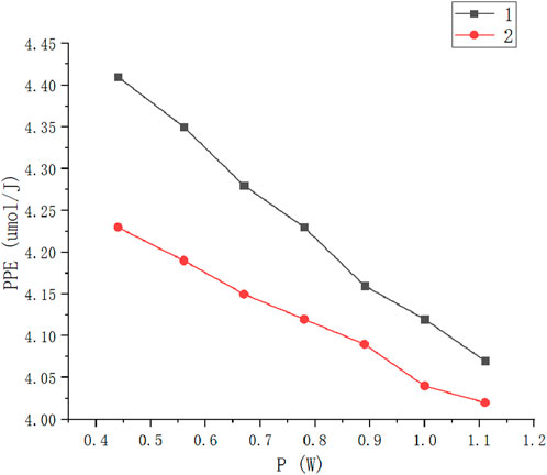
Figure 7. PPE diagram of single and double red light chips.
For multi-chip systems with more than two chips, the mutual light absorption effect becomes more complex, involving interactions among multiple chips. Currently, research on this effect is in its early stages, lacking systematic theoretical support and experimental data. Future in-depth research should focus on establishing quantitative relationships between mutual absorption and parameters like chip spacing, quantity, and arrangement, as well as exploring suppression methods via material and structural design. Our multi-chip optimization will prioritize: 1) Quantifying isolation material reflectivity (directing scattered photons) and thermal stability (reflectivity degradation at high temperatures), 2) Systematically testing 0.1–1.0 mm spacing to identify critical distances balancing absorption reduction and compact design, 3) Evaluating 2/4/6/8-chip configurations to determine optimal chip counts for high-power versus miniaturized applications. These efforts will advance theoretical foundations and practical implementation in plant lighting.
4 Summary
This study proposes a novel assembly approach for red light chips, incorporating both planar optical encapsulant and filler material within a dome-less structure. The filler material is utilized to fully occupy the gap between the lens and the planar optical encapsulant, enabling optimized light distribution through the synergistic interaction of the planar optical encapsulant, filler material, and lens. This design significantly enhances light extraction efficiency. Furthermore, by addressing technical biases, the adoption of PLCC packaging in this design effectively reduces manufacturing costs. The resulting light-emitting module demonstrates a cost-effective solution with high light extraction efficiency. Experimental data indicate that this design improves the light efficiency of PLCC red light devices by approximately 22%, representing a substantial enhancement. Additionally, this paper explores further improvements through the use of dual-core red light devices, providing preliminary evidence that PPE can be further increased. These findings lay the groundwork for future design optimizations and control strategies. Overall, this design approach exhibits significant potential for practical applications.
Data availability statement
The original contributions presented in the study are included in the article/supplementary material, further inquiries can be directed to the corresponding author.
Author contributions
LH: Conceptualization, Methodology, Writing – original draft. YH: Data curation, Writing – original draft. YX: Conceptualization, Funding acquisition, Investigation, Methodology, Project administration, Writing – review and editing. HP: Data curation, Validation, Writing – review and editing. SW: Writing – review and editing, Investigation, Methodology. YS: Supervision, Writing – review and editing.
Funding
The author(s) declare that no financial support was received for the research and/or publication of this article.
Conflict of interest
Authors LH, YH, YX, and HP were employed by Hangzhou Hpwinner Opto Corporation.
The remaining authors declare that the research was conducted in the absence of any commercial or financial relationships that could be construed as a potential conflict of interest.
Generative AI statement
The author(s) declare that no Generative AI was used in the creation of this manuscript.
Any alternative text (alt text) provided alongside figures in this article has been generated by Frontiers with the support of artificial intelligence and reasonable efforts have been made to ensure accuracy, including review by the authors wherever possible. If you identify any issues, please contact us.
Publisher’s note
All claims expressed in this article are solely those of the authors and do not necessarily represent those of their affiliated organizations, or those of the publisher, the editors and the reviewers. Any product that may be evaluated in this article, or claim that may be made by its manufacturer, is not guaranteed or endorsed by the publisher.
References
1. Xu Q. LED plant lighting technology and industry status analysis. Lamps & Lighting (2016) 128(2):33–5+48. (in Chinese).
2. Nemali K. History of controlled environment horticulture: greenhouses. HortScience (2022) 57(2):239–46. doi:10.21273/HORTSCI16160-21
3. Massa GD, Kim HH, Wheeler RM. Plant productivity in response to LED lighting. HortScience (2008) 43(7):1951–6. doi:10.21273/HORTSCI.43.7.1951
4. Shin SK, Murthy NH, Heo WJ. The effect of light quality on the growth and development of in vitro cultured doritaenopsis plants. Acta Physiologiae Plantarum (2008) 30(3):339–43. doi:10.1007/s11738-007-0128-0
5. Von Wettberg EJ, Johanna S. Physiological mechanism of population differentiation in shade-avoidance responses between woodland and clearing genotypes of Impatiens capensis. Am J Bot (2005) 92(5):868–74. doi:10.3732/ajb.92.5.868
6. Lin KH, Huang MY, Huang WD. The effects of red, blue, and white light-emitting diodes on the growth development, and edible quality of hydroponically grown lettuce (Lactuca sativa L. var. capitata). Scientia Horticulturae (2013) 150:86–91. doi:10.1021/jf4039937
7. Kyeong JK, Hyun SL, Hoon JS, Moon JP. Analysis of natural ventilation characteristics of venlo-type greenhouse with continuous roof vents. Biosyst Eng (2011) 36(6):444–52. doi:10.5307/jbe.2011.36.6.444
8. Díaz-Galián MV, Torres M, Sanchez-Pagán JD. Enhancement of strawberry production and fruit quality by blue and red LED lights in research and commercial greenhouses. South Afr J Bot (2021) 140:269–75. doi:10.1016/j.sajb.2020.05.004
9. Grazia MA, Federico A, Petronia C. Getting back to nature: a reality check for experiments in controlled environments. J Exp Bot (2017) 68(16):4463–77. doi:10.1093/jxb/erx220
10. Cedillo GMV, Nájera C, Signore A. Analysis of global research on vegetable seedlings and transplants and their impacts on product quality. J Sci Food Agric (2024) 104(9):4950–65. doi:10.1002/jsfa.13309
11. Zhan X, Zhang J, Wang X. Progress on silicone packaging materials for power LED. Proced Eng (2012) 27:687–92. doi:10.1016/j.proeng.2011.12.506
12. Fujita S, Yoshihara S, Sakamoto A. YAG glass-ceramic phosphor for white LED (I): background and development, 5941. SPIE (2005). p. 186–92.Fifth Int Conf Solid State Lighting. doi:10.1117/12.614668
13. Mazlan M, Rahim A, Iqbal M. The comparison between four PLCC packages and eight PLCC packages in personal computer (PC) using computational fluid dynamic (CFD), FLUENT SoftwareTM using epoxy moulding compound material (EMC). Adv Mater Res (2013) 2602(795):174–81. doi:10.4028/www.scientific.net/AMR.795.174
14. Zhou S, Shi L, Cui S. Schottky-contact intrinsic current blocking layer for high efficiency AlGaInP-based red mini-LEDs. Opt Lett (2024) 49(13):3765–8. doi:10.1364/OL.526155
15. Sun YJ, Yang TJ, Jiang CY. GaN-based thin film vertical structure light emitting diodes fabricated by a modified laser lift-off process and transferred to Cu. Chin Phys Lett (2010) 27(12):127303. doi:10.1088/0256-307X/27/12/127303
16. Ho JS, Kim JB, Ryu JC. Enhancement of wall-plug efficiency in vertical InGaN/GaN LEDs by improved current spreading. Opt Express (2012) 20(S2):A287–A292. doi:10.1364/OE.20.00A287
17. Abdel-wahed SM. Magnetohydrodynamic ferro-nano fluid flow in a semi-porous curved tube under the effect of hall current and nonlinear thermal radiative. J Magnetism Magn Mater (2019) 474347–54. doi:10.1016/j.jmmm.2018.11.050
18. Anon. Material specifications and model number document (2014). Available online at: https://www.pztest.com/index.php?c=show&id=1388.
Keywords: LED, plant lighting, PLCC, light efficiency, red light
Citation: Hu L, Hu Y, Xia Y, Peng H, Wei S and Shi Y (2025) A high-efficiency red light-emitting module utilizing PLCC packaging for plant lighting applications. Front. Phys. 13:1641628. doi: 10.3389/fphy.2025.1641628
Received: 05 June 2025; Accepted: 04 August 2025;
Published: 25 August 2025.
Edited by:
Haisu Li, Beijing Jiaotong University, ChinaReviewed by:
Yajun Pang, Hebei University of Technology, ChinaBin Yin, Ocean University of China, China
Copyright © 2025 Hu, Hu, Xia, Peng, Wei and Shi. This is an open-access article distributed under the terms of the Creative Commons Attribution License (CC BY). The use, distribution or reproduction in other forums is permitted, provided the original author(s) and the copyright owner(s) are credited and that the original publication in this journal is cited, in accordance with accepted academic practice. No use, distribution or reproduction is permitted which does not comply with these terms.
*Correspondence: Yu Xia, Y2hpbmF4aWF5dUBxcS5jb20=