- 1Leslie A. Rose Department of Mechanical Engineering, South Dakota School of Mines and Technology, Rapid City, SD, United States
- 2Department of Mechanical and Aerospace Engineering, University of Florida, Gainesville, FL, United States
- 3Department of Electrical and Computer Engineering, University of Florida, Gainesville, FL, United States
Gibbs was the first person to represent a phase interface by a dividing surface. He defined the dividing surface as a mathematical surface that has its own material properties and internal dynamics. In this paper, an alternative derivation to this mathematical surface is provided that generalizes the concept of dividing surface to fluid fronts beyond that of just a phase or material interface. Here, this extended definition of dividing surface is referred to as the extended dividing hypersurface (EDH), as it is not just applicable to a surface front but also to a line and a point front. This hypersurface represents a continuum approximation of a diffused region, where fluid properties and flow parameters vary sharply but continuously across it. This paper shows that the properties and equations describing an EDH can be derived from the equations describing the diffused region by integrating it in the directions normal to the hypersurface. This is equivalent to collapsing the diffused region in the normal direction. Hence, ensuring that the EDH is both kinematically and dynamically equivalent to that of the diffused region. Various canonical problems are examined to demonstrate the EDH’s ability to accurately represent different types of fluid and flow fronts, including static and dynamic interfaces, shock fronts, and vortex sheets. These examples emphasize the EDH’s capability to represent various functionalities within a front, the relationship between the flux of quantities and hypersurface quantities, and the importance of considering the mass of the front and associated dynamics.
1 Introduction
A front is often accompanied by rapid changes in scales, multiphysics, geometrical complexities, and intriguing chemical phenomena, making it an ideal benchmark to expand our knowledge beyond the confines of the continuum field. A front refers to a boundary separating two or more sets of homogeneous quantities in a continuum field. Across the front, one or more of these field quantities are usually discontinuous. While some of these quantities pertain to the material properties of the media, others are associated with its kinematics and dynamics. Examples of commonly occurring fronts in fluid mechanics, across which fluid properties and/or flow parameters are discontinuous, are listed in Table 1. These fronts can be categorized into two types. The first type is referred to as the physical front, which exhibits sharp gradients in fluid and flow parameters at length scales that are below the experimental or numerical observable limit [1]. Moreover, the equation of state and thermodynamic properties of the physical front differ from those of the surrounding homogeneous media [2, 3]. Examples of physical fronts include material or phase interface, gravity wave front [4–6], and shock front Shapiro [7].
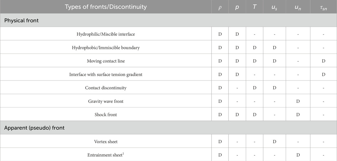
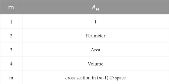
Table 1. List of fronts and corresponding field quantities that are discontinuous across it. The fluid properties or flow parameters that are discontinuous are labelled as “D”. Here,
The second type is referred to as the apparent front, characterized by gradients that exist at length scales above the observable limit but can be approximated as a discontinuity for analytical and numerical simplicity. In this case, the equation of state and the thermodynamic properties within the front are the same as those of the surrounding homogeneous media. Examples of apparent fronts include a vortex sheet and an entrainment sheet, which are commonly used to describe a boundary layer or mixing layer. Among these examples of a front is a well-known discontinuity corresponding to the jump in pressure across a curved fluid-fluid interface. This jump in pressure is attributed to interfacial tension, which is the thermodynamic property of an interface in an equilibrium system. This then begs the following questions: (1) whether the fluid interface possesses other material properties? (2) Does it have any internal dynamics if the interface is in a non-equilibrium system? And (3) if the material and phase interface can have their own properties and internal dynamics, could other fluid and flow fronts also possess their own distinct material properties and internal dynamics? The fact that a fluid interface could have material properties analogous to those of a bulk fluid and its own internal dynamics was first recognized by Gibbs [8].
Gibbs introduced the concept of a dividing surface to represent a fluid interface, more specifically, a phase interface. The dividing surface is a two-dimensional mathematical surface with zero thickness, which has its own properties and internal dynamics [8–10]. Gibbs proposed a phenomenological description of the thermodynamic relations for the dividing surface, which represents a phase interface in a body at rest or equilibrium. After nearly 3 decades, Scriven [9] extended this concept of dividing surface to non-equilibrium systems by deriving a model that described the internal dynamics of the fluid within the dividing surface [9, 11]. Though Scriven accounted for the coupling of the dividing surface with its surrounding bulk media, the mass transfer between the dividing surface and the bulk fluid surrounding it was ignored. The effect of mass transfer was later included in the governing equations by Slattery [10]. This was done by expanding Gibbs’ definition of homogeneous media to one where the constitutive equations apply uniformly. In these three models, the thermodynamic relations [8], the transport equations, and the conservation of mass, momentum, and energy of the dividing surface [9, 10] were all independently defined as a two-dimensional analogue to the corresponding three-dimensional bulk equations. The last question posed in the previous paragraph still remains unanswered: whether a dividing surface concept can also describe other fluid fronts.
This paper addresses the question by examining the characteristics of fluid fronts. It is asserted that the actual physical front is a diffused region with three dimensions and a finite thickness. Within this region, fluid and flow parameters exhibit sharp but continuous variations across its width. It is important to note that the conventional representation of a front as a hypersurface in continuum theory is a limiting case of this diffused region. As a result, the authors propose a systematic derivation of the dividing surface from the 3D bulk conservation equations that accurately describe this diffused region. This generalized dividing surface is referred to as the extended dividing hypersurface (EDH). The EDH equations are derived by collapsing the dimension across the width of the diffused region, mathematically achieved through integration along its width. This mathematical treatment ensures that the EDH is kinematically and dynamically equivalent to the diffused region, representing the real physical front in its entirety.
To validate the EDH model and its generalization, the authors conduct a comprehensive analysis of canonical problems that involve fluid fronts. These problems are (1) stationary fluid with varying miscibility, (2) stratified flow through a converging-diverging section, (3) the shock tube problem, (4) the vortex entrainment sheet, and (5) unsteady bubble dynamics.
The selected problems in this study serve four primary purposes. Firstly, they demonstrate that the extended dividing hypersurface (EDH) is capable of accurately capturing the dynamics of different types of fluid and flow fronts, not limited to phase or material interfaces. Secondly, they highlight that the EDH can effectively represent various functionalities within a front, going beyond the commonly described monotonicity distribution in literature, resulting in new classes of fronts. Thirdly, they illustrate the relationship between the flux of
The paper is outlined as follows: Section 2 defines a diffused region, front, and hypersurface. Here, a brief description is provided of how the collapse of dimension is achieved mathematically, along with an overview of the methodology used to obtain the governing equations of an EDH. Section 3 presents the derivation of equations related to EDH. In Section 4, the details of the numerical simulations used for validating the EDH model are presented. Finally, the results are presented and discussed in Section 5.
2 Overview of methodology and general definitions
Prior to deriving the governing equations for the EDH, it is helpful to: 1) introduce key definitions and nomenclature utilized in this study, 2) provide an overview of the concept of spatial dimension collapse, and 3) outline the adopted methodology for deriving the governing equations for the EDH.
2.1 Defining a diffused region, the hypersurface, and the extended dividing hypersurface
As previously stated, a front is referred to as a fluid feature across which one or more fluid or flow parameters is considered to be discontinuous. This can be mathematically and computationally represented as a diffused region with finite volume or a hypersurface with zero thickness.
2.1.1 Diffused region
In this paper, a diffused region is defined as a region with finite thickness in
The diffused region is depicted in Figure 1. The boundary of the domain containing the homogeneous media and the embedded diffused region or hypersurface is represented by ‘
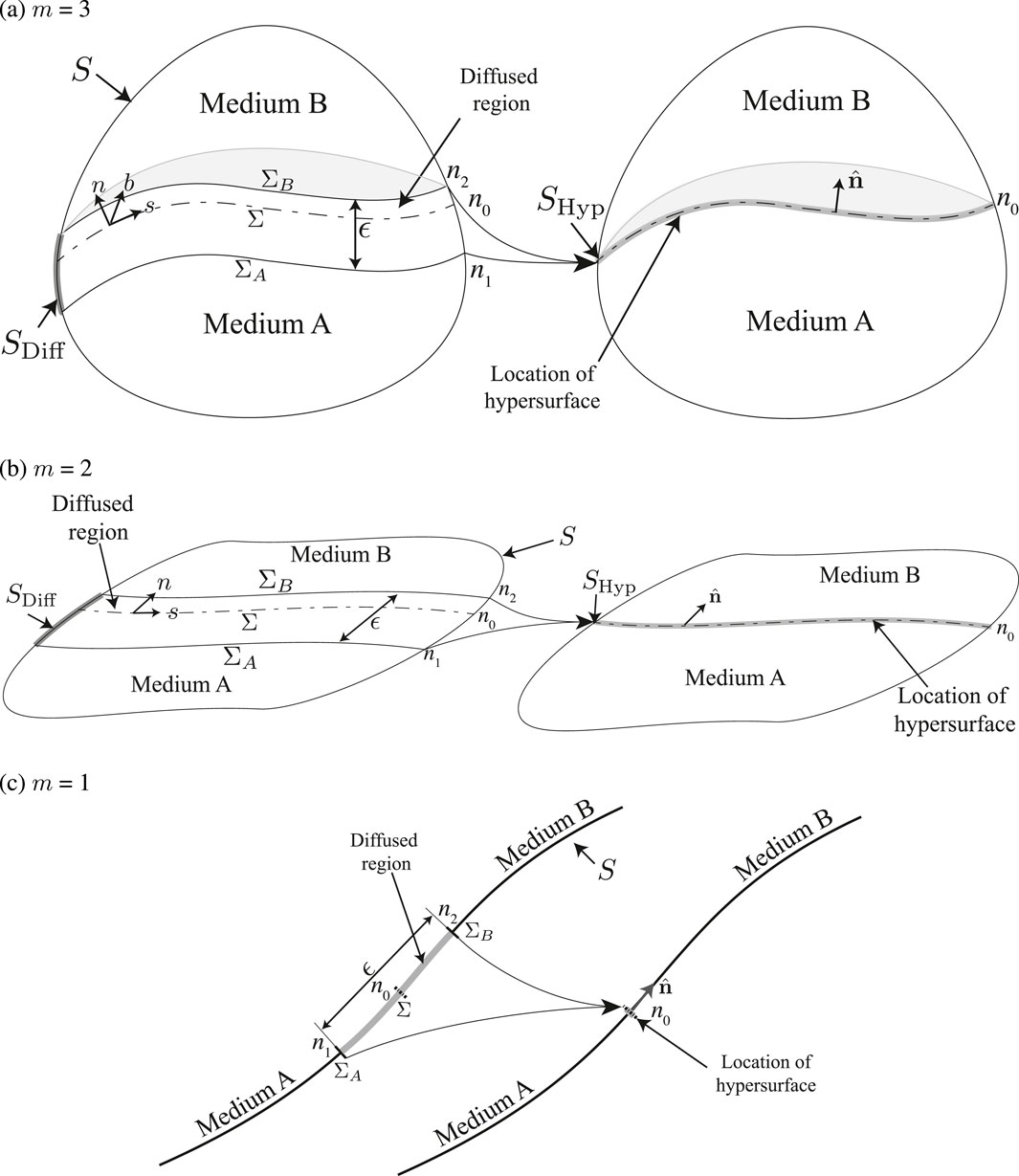
Figure 1. Schematic illustrating two homogeneous media separated by a diffused region, with an equivalent representation of the media separated by a hypersurface. Figures (a)–(c) represent an arbitrary control volume, surface, and line, respectively. The boundary of the domain encompassing the homogenous media and the embedded diffused region or the hypersurface, is denoted by ‘
2.1.2 Hypersurface
In mathematics, a hypersurface is a manifold of dimension
2.1.3 Extended dividing hypersurface (EDH)
An extended dividing hypersurface is defined as a type of hypersurface that accurately represents and encompasses the cumulative (integrated in the direction normal to the front) kinematics and dynamics of a front as a diffused region. The EDH distinguishes itself from a diffuse region by its zero thickness in the front normal direction. Across the EDH, the field quantities undergo discontinuous changes rather than continuous variations. In comparison to a Gibbs’ dividing surface, the EDH separates not only two homogeneous media but also the same media at different dynamic states. Finally, the EDH serves as an extension to the Gibbs’ dividing surface, which was initially limited to representing material or phase interfaces. The EDH, in contrast, offers the flexibility to represent any fluid front. Examples of such fronts include vortex sheets, shock fronts, moving contact lines, and triple points. Hence, the term “hypersurface” is preferred over “surface” as it encompasses not only geometric surfaces but also fronts that exist as curves, lines, and points.
In Figure 1,
2.2 Overview of collapsing a spatial dimension mathematically
The method of collapsing a dimension can be elucidated using a schematic, as depicted in Figure 2. We examine two scenarios characterized by distinct distributions of an arbitrary parameter
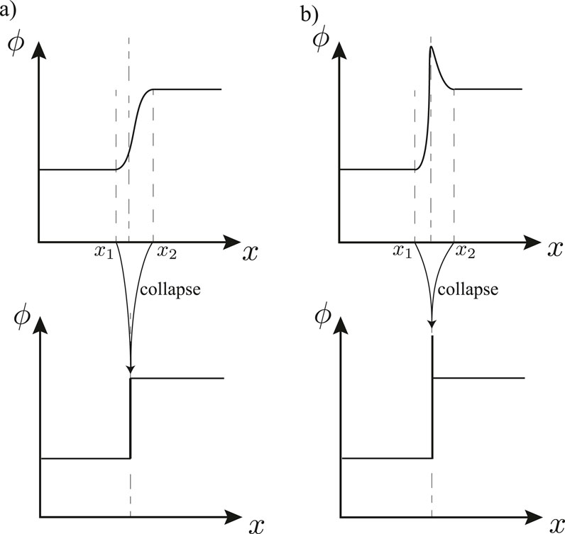
Figure 2. Schematic illustrating two cases with identical bulk media states, where the diffused region (with a sharp but continuous variation in
2.3 Overview of deriving hypersurface equations
The derivation of governing equations for an extended dividing hypersurface (EDH) is based on the fundamental objective of capturing the cumulative kinematics and dynamics of a front as a diffused region. To accomplish this, the equations governing the EDH are derived from those of the diffused region. This process can be divided into three distinct steps, which are as follows.
1. Describe the diffused region (Section 3.1.1). As previously mentioned, we view the diffused region of finite thickness, in
2. Derive equations for an actual extended dividing hypersurface, by collapsing the diffused region (Section 3.1.2). The diffused region is collapsed in dimensions normal to the EDH by integrating the equations describing it, along these directions, as seen in Figure 3b. This results in a set of equations describing an EDH. Therefore, in the EDH, the various flow and fluid quantities associated with the diffused region are now treated as quantities lumped in the normal direction. In this paper this collapsed diffused region is referred to as the actual extended dividing hypersurface. This is because often, we are not concerned with just modeling the front as an isolated entity, but as an entity embedded in a homogeneous media, for which one last step needs to be done.
3. Derive equations for an effective extended dividing hypersurface (Section 3.1.3). As a consequence of the collapse, a void is created in the space previously occupied by the diffused region. This void is considered to be occupied by the adjacent homogeneous media of

Figure 3. Schematic depicts the three steps required to derive the equations describing an extended dividing hypersurface from the equations for a diffused region. The figure (a) shows the diffused region with a finite thickness. The figure (b) shows the extended dividing hypersurface with zero thickness, achieved by collapsing the diffused region and the corresponding void created as a result of it. The figure (c) presents the EDH embedded in a homogenous media with the void now being occupied by the two homogeneous media.
With this basic framework in mind, the equations for an EDH can be derived. In order to completely and properly describe a fluid system, a set of governing equations, boundary, and initial conditions are required. The governing equations comprise of the conservation of mass, momentum, and energy, and the equation of state. In order to ensure there is no loss of generality, the equations are stated for a region in an arbitrary
3 Deriving equations for hypersurfaces/mathematical formulations
3.1 Deriving mass conservation for an extended dividing hypersurface
As previously mentioned, the derivation of governing equations for an extended dividing hypersurface can be divided into three steps. The first of the three steps is describing the diffused region.
3.1.1 Describing the mass conservation for a diffused region
In the case of a fluid media containing a diffused region, a single set of governing equation is used to describe the homogeneous media and the diffused region in
Here,
Here, considering an orthogonal coordinate system,
Here,
3.1.2 Derive mass conservation for an actual extended dividing hypersurface, by collapsing the diffused region
Our objective is to derive conservation equations for an EDH which is kinematically and dynamically equivalent to that for a diffused region. The mass conservation equation for the EDH is obtained by collapsing the dimensions normal to the hypersurface. This is mathematically performed by integrating the conservation equation for a diffused region in that direction.
The mass conservation for a hypersurface is evaluated by first splitting the gradient operator
Here,
The reason for this decomposition of the gradient operator can be further explained by using a rectangular diffused region as an example, as seen in Figure 4. The tangential component of the gradient operator is used to denote the mass flux through left and right boundaries of the diffused region (

Figure 4. Schematic of a rectangular diffused region being collapsed in the normal direction to a hypersurface.
With the gradient operator decomposed, the integral in the direction normal to the hypersurface can be now separated (Equation 5):
Here,
The term
The term
Here,
Finally, the diffused region is collapsed in dimensions normal to the hypersurface by integrating each term in this direction. Collecting terms
Here,
3.1.3 Derive mass conservation for an effective extended dividing hypersurface
In this paper it is considered that the void is replaced by the homogeneous media adjacent to it. Therefore, an effective EDH adjusts for the effect of the dynamics created by the homogeneous media that ends up occupying this void. Before evaluating the effective EDH, we first present the equation of mass conservation for this added homogeneous fluid in lumped form:
Here, the subscripts
Similarly, for fluid B.
This added material, and the dynamics as a result of it, needs to be adjusted for, in order for the homogeneous system with an embedded hypersurface to be identical to the system with a diffused region, which it is trying capture. Otherwise you would be double counting mass. This is taken care of by subtracting this additional contribution (Equations 11, 12) from that of the actual EDH (Equation 10). The resulting equation (Equation 13) is called the mass conservation for an effective EDH or will be referred to here as just the mass conservation for an EDH:
Here,
Finally, observing that time derivative of
The first line in the above equation is analogous to the standard mass conservation represented in
3.2 Momentum conservation for a hypersurface
Now that the mass conservation for an EDH has been presented, similar steps can be used to obtain the momentum and energy conservation equations for an EDH. The principal of momentum conservation states that the time rate of change of linear momenta of a material region is equal to the sum of forces acting on the region. This is mathematically presented as (Equation 15):
where
Further, writing in terms of field quantities and using the transport equation, we obtain the integral form of conservative momentum equation for the diffused region (Equation 16):
Here,
Similar to the mass conservation, the gradient operator in the integral form of conservative momentum equation for diffuse hypersurface is decomposed into tangential and normal components. In addition, the integral normal to the hypersurface is separated (Equation 17):
Using the Leibniz’s rule and collapsing the diffused region by integrating in the direction normal to the EDH, the momentum conservation for an actual EDH is derived (Equation 18).
Finally, adjusting for the effects of the added homogeneous media, the momentum conservation for the effective hypersurface is presented as.
Here, there are two sets of additional terms to account for the flux due to spatial changes in the location of the EDH, referred to as ‘jump in bulk momentum and stress due to variation in Dividing Hypersurface location’ in Equation 19. One of those term accounts for the momentum flux
3.3 Energy conservation
The principal of conservation of total energy states that the time rate of change of total energy of a material region is equal to the net energy gained by the system from heat flux through the surface and work done on it. This is given as (Equation 20),
where
As previously done for mass and momentum equations, using the Reynold’s transport theorem the equation for conservation of total energy is given as (Equation 21),
Here, total energy
Since the steps are similar to that of mass and momentum conservation, we skip the intermediate steps and present the final relation for the conservation of energy for an effective EDH (Equation 22).
Finally, with the conservation equations for an EDH presented, the equation of state for the EDH, followed by the boundary and initial conditions, are briefly discussed.
If in addition to velocity; density, temperature and pressure are also unknown, then an additional relation is required. This is given by the equation of state. In this paper it is assumed that the diffused region has an equation of state same as that of the homogeneous media and the EDH has an equation of state analogous to it. This might not necessarily always be the case. After deriving the above governing equations for an EDH it would not come as a surprise that the equation of state also needs to be re-derived by considering the collapse of the dimension. This is beyond the scope of the current paper and is a topic that shall be addressed in future work.
Finally, in order to close the system, initial and boundary conditions are required. Similar to homogeneous media, the field value of hypersurface quantities such as, velocity vector, pressure, density and temperature needs to be know at time
3.4 Defining effective hypersurface quantities and identifying the location of the extended dividing hypersurface
3.4.1 Defining hypersurface quantities
Following the derivation of the governing equations for the extended dividing hypersurface, the next step involves discussing the definitions of effective hypersurface quantities as well as the location of the EDH itself. When it comes to evaluating the hypersurface quantities, especially intensive quantities, it is done so by preserving the corresponding extensive quantities in a diffused region. That is, velocity is evaluated by preserving momentum, stress is computed by preserving the corresponding force, and temperature by preserving the heat energy. Therefore, for an arbitrary extensive or intensive parameter
This definition is similar to that used to derive the governing equation for effective EDH. Here,

Figure 5. Schematic representation of a diffused region corresponding to a, (a) planar and (b) curved diffused region.
In order to calrify the definition for a hypersurface quantity, the evaluation of hypersurface density will be explored. This evaluation considers a diffused region associated with both a curved and a planar hypersurface of unit depth, as depicted in Figure 5. However, before delving into the specific evaluation, a conceptual overview will be presented on how the hypersurface quantity is computed (Equation 25).
The definition proposed in this study differs from that used by Slattery [10] in terms of defining surface quantities based on extensive quantities. The underlying concept behind this approach is that the total mass remains constant between a diffused region and an extended dividing hypersurface (EDH). However, the magnitude of density, whether it is expressed as mass per unit volume, mass per unit area, or mass per unit length, may vary. Similarly, the total force remains constant between a diffused region and a hypersurface, but the stress, whether it is measured as force per unit area or force per unit length, may differ. This is the rationale behind preserving the extensive quantities between the diffused region and the EDH, while the intensive quantities associated with the EDH are then derived from their corresponding extensive quantities. Therefore, in the case of a planar hypersurface (Figure 5a),
Here, it is assumed that the homogeneous media have a constant density. Hence, the extrapolated density adjacent to fluid A and B are
Hence, in the case of a curved hypersurface, its density depends on the radius of curvature of the hypersurface.
3.4.2 Location of extended dividing hypersurface
From the definition of a hypersurface quantity it can be seen that its magnitude is directly dependent on the location of the EDH. The question that then remains is where in the diffused region is the EDH located? The answer is that the location of EDH is arbitrary. It can be any location as long as it is within the diffused region. The EDH and its location is not unique to a given diffused region, rather it is dependent on (1) a pre-specified criteria and/or (2) the flow or fluid quantity the criteria is based on. The clarification of the aforementioned concepts is provided below.
Since the exact location of the EDH within the diffused region is arbitrary, additional information is required as an initial condition. This is provided in the form of criteria on which the location and consequently the EDH can be defined. The choice of criteria used to determine the location of EDH is based on convenience and does not effect the dynamics of the system as a whole, as long as the criteria are consistently applied throughout the set of equations describing the EDH. For example, Gibbs’ proposed an EDH location based on surface tension and also one based on equimolar contributions of the two fluids [8]. On the other hand Slattery defined the EDH to be located at a position where there is no effective mass of the EDH [10]. This dependence of the EDH location on the choice of criteria is no different than, for example, trying to identify the center of a ship. The center of a ship, can be defined as the center-of-gravity, or the center of buoyancy, or the metacenter.
Secondly, it is a common assumption in the literature that the EDH location corresponding to its mass, momentum, and total energy are the same [8, 10]. This is not always the case. For example, if we choose the criteria that EDH is located where the effective mass, momentum, and total energy are all zero, then it will result in three different locations. Only for the case where the density distribution within the diffused region is a constant, will they all be at the same location. This dependence of the EDH location on a conserved flow quantity is analogous to the definition of the boundary layer thickness. For example, the thickness of the boundary layer can be based on the mass (displacement-thickness) or momentum (momentum-thickness), both of which are not always identical.
Considering that the EDH and its location are not unique to a diffused interface, the velocity of the EDH is not unique either. This is because the velocity of the EDH is computed as the time rate of change of its location,
4 Test cases and numerical setup for validation
In this paper, canonical example problems are used to validate the derived continuum model of an extended dividing hypersurface (EDH), which represents a fluid front. In order to validate it whenever possible, results are compared to the analytical solutions. In instances where an analytical solution is unavailable, a more fundamental approach of molecular dynamics (MD) simulations is used to create a reference solution for comparison. MD simulations are used because of their ability to resolve the front.
In the case of examples using molecular dynamics simulations, bulk values from MD simulations at the boundaries of the diffused region are used as an input to the EDH equations. In the case of the example problem with an analytical solution, both the EDH equation and bulk equations are solved simultaneously. In this section, the problem geometry is described for each example, along with details of the simulations.
4.1 Molecular dynamics simulations
The LAMMPS package is used to perform molecular dynamics (MD) simulations [14].
Here, the pairwise interaction of molecules, separated by a distance
Here,
The temperature is maintained using a Langevin thermostat with a damping coefficient of
Here,

Table 3. List of different test cases. Here,
The equations of motion were integrated using the Verlet algorithm [15, 16] with a time step
4.1.1 Stationary fluids with varying miscibility
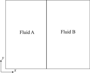
Two stationary immiscible or partially miscible fluids at a constant temperature and pressure are simulated as shown in Figure 6. The domain is periodic in all directions.
The domain size is
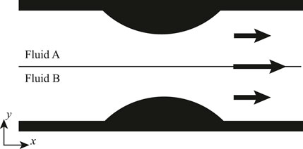
4.1.2 Stratified flow through a converging diverging section
In this test case, a varying cross sectional area is modeled by a converging-diverging section in the channel, with a periodic domain in the
The domain size is
4.1.3 Shock tube problem
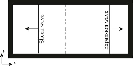
The canonical shock tube problem considered here is a long tube which is closed at both ends. A diaphragm separates the region of high-pressure fluid on the right from the region of low-pressure fluid on the left. When the diaphragm is broken at
The domain size is
4.2 Example with an analytical solution
4.2.1 Bubble dynamics
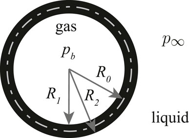
The last example problem looks at the evolution of a bubble when subjected to a non-equilibrium initial condition, as illustrated in the schematic in Figure 9. The non-equilirbium condition is initiated by a high pressure at infinity. The radial evolution of an unstable bubble in an unbounded liquid is given by the Rayliegh-Plesset equation [17–19]. In this paper, the Rayleigh-Plesset equation is modified by considering the physical interface having a finite mass and thickness.
In this example problem, the actual hypersurface description of the EDH is used. The hypersurface is considered to be located
Here, using ideal gas law, the pressure within the bubble,
In order to compute hypersurface quantities, such as hypersurface mass, it is considered that the density sequence (function), describing the density within the interface, is a 4th-order polynomial. In addition, it is assumed that the magnitude and the gradient of density in the radial direction are continuous at the bounds of the interfacial region. This is used to evaluate interfacial quantities analytically.
The evolution of bubble radius is found by simultaneously solving the mass conservation of the hypersurface and the Rayleigh-Plesset equation. This modified system of equations is solved numerically. It must be noted as a means of validating and demonstrating the implementation of the EDH equations, only the hypersurface mass conservation is used for this example. The momentum conservation will be incorporated in future work.
The non-dimensional parameters and initial conditions chosen for this parametric numerical study are
5 Results and discussion
The primary objective of this paper is to expand upon the concept of a dividing surface initially introduced by Gibbs. The aim is to generalize this concept to encompass any fluid and flow front, going beyond just the phase interface. In order to achieve this goal, the authors examine a series of canonical problems involving fluid and/or flow fronts.
These problems serve four main purposes.
1. They illustrate that the extended dividing hypersurface (EDH) has the capability to accurately capture the dynamics of not only phase or material interfaces but also other types of fluid and flow fronts, specifically shock front (physical front) and vortex sheet (apparent front).
2. They emphasize that the distribution of monotonicity within a front, as commonly described in literature, is just one of several possible functionalities that the EDH can capture.
3. They demonstrate the relationship between the flux of
4. They underscore the importance of acknowledging the mass of the front and consequently demonstrating its impact on the dynamics of the front.
5.1 Stationary fluids with varying miscibility
We start with the simplest example of two stationary fluids adjacent to each other, see Figure 6. As a result of the fluids being stationary the EDH has no dynamics. Hence, the only non-zero quantity associated with the EDH are the thermodynamic quantities. Furthermore, since we consider a system with a planar EDH and a constant temperature, the only thermodynamic quantity that is discontinuous across the EDH is density. As we have done through the course of this paper, looking at density or mass of the EDH serves as the best starting example to understand hypersurface quantities.
Different test cases with varying density ratios and miscibilities are presented. This helps us demonstrate various nuances of hypersurface quantities and the common assumptions (explicit or implicit) made about them in the literature. We first put to test the assumption that the density profile is monotonic across the diffused region and the local value being never greater or less than the value of bulk densities as was shown in Figure 2. This is especially true, when numerically modeling a material or a phase interface (front-tracking, level-set, phase field methods [20]). Referring to Figure 10, it is seen that in the first two cases the individual density distribution is monotonic, but the combined densities are not. The behavior of both individual and combined density profiles in case (c), is closest to the monotonic assumption made in literature, but it also happens to be a trivial solution. As for the last example, of a stationary gas next to a liquid, case (d), the local density distribution of fluid A, is also not monotonic.
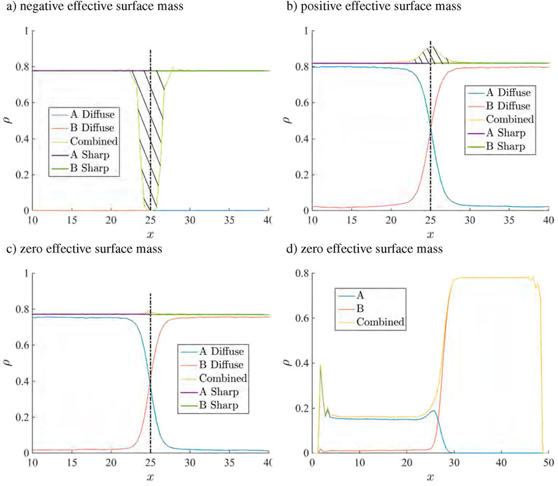
Figure 10. Compares the density distribution of individual fluids along with the total density, across the diffused region for four different types of interfaces. (a–c) Considers the two fluid to have identical density but varying miscibilities. Here individual density profiles show a monotonic behavior. (d) Considers a case with the two fluids having two different densities, with one of the fluid showing a non-monotonic behavior.
Next, we look at the actual and effective hypersurface mass, which is evaluated as per the definition presented in Equation 23. Here, we consider the EDH to be located where the density profiles of the two fluids intersect, as seen in Figure 10 and denoted by a dashed line. Bold line shows the extrapolated bulk density of individual fluids. Hence, the effective hypersurface mass, or as Gibbs calls it, the excess mass, is given by the hatched region in the figure. It can be seen that figures (a), (b) and (c) give a negative, positive and zero effective mass, respectively. This is contrary to what is commonly assumed in literature. It is commonly assumed that the interface has no mass, when considering perfectly immiscible fluids in continuum simulations [20], whereas results from MD, presented here, show that it can in fact have both a positive and negative effective mass. The hypersurface density is not separately discussed, because as mentioned in section 3.4, it is derived from hypersurface mass.
In the static case, with no curvature, an argument can be made that because the relative thickness of the diffused region is negligible compared to the length scale of the homogeneous media, the zero hypersurface mass is a good assumption. While this is true for effective mass, the same cannot be always said for effective momentum, energy or stress. For instance, effective hypersurface linear stress gives the hypersurface pressure, which is nothing but the mechanical surface tension, which we know not to be negligible. Hence, from MD simulation results and definition of hypersurface quantities presented in Section 3.4 a case is made that the assumptions.
1. That distribution across a diffused region is monotonic,
2. The local value within this region lies always within the range of the corresponding bulk values, and
3. The effective hypersurface mass is zero, are not always true.
5.2 Stratified flow through a converging diverging section
In the previous example since there was no gradient along the EDH, there were no internal dynamics or viscous stresses in the EDH. In this section a 2D stratified fluid flow through a section with varying cross sectional area is considered. The varying cross-section of the channel results in accelerating the flow. This example is used to demonstrate the relationship between the mass flux of the bulk fluid into the EDH and the hypersurface dilatation. This relation is directly obtained from the mass conservation equation for the EDH, and as such also acts as its validation. In addition, we discuss the recent finding by Thalakkottor and Mohseni [21], suggesting the deviation of mechanical and thermodynamic surface tension in the presence of hypersurface dilatation.
In the case of a stratified Couette flow the list of relevant assumptions made are as follows.
1. Steady state, no time rate of change of hypersurface quantities.
2. No source of hypersurface mass or momentum.
3. No hypersurface body force.
4. Location of the bounds of the boundary layer (or width) does not change with time and space.
5. Since we are considering a periodic or 2D problem, there is no surface shear
6. We assume that there is no surface dilatation,
7. There is no surface gradient in surface pressure.
Applying these assumptions, the governing equations for the actual extended dividing hypersurface become (Equations 31, 32):
Mass conservation,
Momentum conservation,
Similarly, the conservation equations for the effective extended dividing hypersurface reduce to (Equations 33, 34):
Mass conservation,
Momentum conservation,
Recalling that the conservation of mass for an EDH is obtained by collapsing the dimension and integrating the conservation equation of the homogeneous media in the normal direction. When the dimension is collapsed, the term
![Graph showing two overlapping datasets plotted against \( x(\sigma) \) on the x-axis, ranging from 0 to 120, and a y-axis range from -0.5 to 0.5. The blue squares represent \([\rho v]\) and align closely with the red line representing \(\frac{\partial}{\partial x} (\rho u)^{(m-1)}\). A vertical dashed line is present at \( x(\sigma) = 60 \).](https://www.frontiersin.org/files/Articles/1652090/fphy-13-1652090-HTML/image_m/fphy-13-1652090-g011.jpg)
Figure 11. Comparing of hypersuface mass flux within the EDH (or surface dilatation) with the jump in mass flux of the homogenous bulk media across the EDH. These results from MD simulation help confirm the EDH mass conservation equation, Equation 41. The black dash-dot line represent the location of the throat of the channel.
Another important consequence of the surface dilatation is that the mechanical surface tension is no longer equal to the thermodynamics surface tension. Recently [21], presented that analogous to the relation between mechanical and thermodynamic pressure, mechanical and thermodynamic surface tension are related as
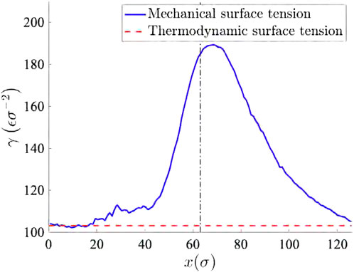
Figure 12. Deviation of local mechanical surface tension value from the thermodynamic surface tension. The black dash-dot line represent the location of the throat of the channel.
5.3 Blasius boundary layer
So far all test cases have been where material/phase interfaces have been represented as an EDH. Here, we demonstrate that the EDH can be used to model a viscous boundary or shear layer. This is done by showing that the vortex-entrainment sheet, recently introduced by DeVoria and Mohseni [22]; Xia and Mohseni [23] is just a limiting case of the EDH presented here. The sheet differs from the conventional vortex sheet by allowing mass and consequently momentum in the sheet.
To demonstrate a boundary layer, the Blasius boundary layer is considered which is a special case of flat plate boundary layer. Here, the boundary layer is formed on a semi-infinite flat plate, with a constant free-stream flow. This requires the following assumptions to be made.
1. Steady state, no time rate of change of hypersurface quantities.
2. No source of hypersurface mass or momentum.
3. No hypersurface body force.
4. Location of the bounds of the boundary layer (or width) does not change with time.
5. Velocity on the side of EDH next to the stationary wall is zero,
6. The fluid outside the boundary layer is assumed to be irrotational. Therefore, jump in shear stress
7. Since we are considering a periodic or 2D problem, there is no surface shear
8. There is no surface dilatation,
9. Also there is no surface gradient in surface pressure.
By considering these assumptions the actual extended dividing hypersurface reduces to (Equations 35, 36):
Mass conservation
Momentum conservation
Similarly, choosing the location of hypersurface to be at the wall, the Mass conservation of effective extended dividing hypersurface reduces to (Equation 37),
for a vortex sheet fixed to a stationary wall, since
momentum conservation (Equation 38)
Decomposing into normal and tangential components (Equations 39, 40).
Assuming flow to be incompressible,
The region of validity of the vortex-entrainment sheet was,
5.4 Shock tube problem
In all the test cases considered so far, the extended dividing hypersurface had no normal velocity,
As done before, we first list all the assumptions.
1. Steady state, no time rate of change of hypersurface quantities.
2. 1D flow, no spatial gradients along the length of the EDH.
3. No source of hypersurface mass and momentum.
4. No hypersurface body force.
5. Thickness of the shock front does not change with time.
By considering these assumptions the actual extended dividing hypersurface reduces to (Equations 41, 42):
Mass conservation
Momentum conservation
The mass conservation equation reduces to the Rankine-Hugoniot condition (Equation 43).
Since, the two edges of the shock wave are considered to move with the same speed, after reaching steady state. The equation can be rewritten as (Equation 44),
Hence, if we know the bulk density and velocity, on the two sides of the shock front, we can then evaluate the speed of the shock wave
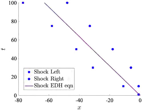
Figure 13. Comparison of displacement x versus time t from molecular dynamics (MD) simulations and surface mass conservation equations. The MD simulation resolves the shock front, providing details on the left and right faces of the front and the shockwave thickness. Both x and t are expressed in corresponding Lennard–Jones (LJ) units.
Although the validity of EDH to represent a shock front is being shown for the canonical normal shock, it has the ability to accommodate more general problems.
5.5 Collapsing bubble
This example investigates the evolution of a bubble under an unstable condition of high pressure at infinity. Specifically, it examines the radial evolution of an unstable bubble in an unbounded liquid, which is described by the Rayleigh-Plesset equation Plesset [18]; Plesset and Prosperetti [25]; Brenner et al. [26]; Brennen [27]; Leal [28]. The evolution of a collapsing bubble is extensively studied in the field of cavitation and multiphase flows. All preceding examples have focused on examining planar interfaces in a steady-state condition. However, this particular example investigates a curved interface within an unsteady state.
The Rayleigh-Plesset (RP) equation is employed to model the time-dependent behaviour of the bubble. However, in typical multiphase flow formulations, the RP equation only considers surface tension as the interfacial property and incorporates the corresponding pressure jump. Consequently, it neglects the interface mass and associated dynamics. In this study, we demonstrate that by incorporating the conservation equation for interfacial (front) mass in conjunction with the Rayleigh-Plesset equation, the evolution of the interface undergoes significant changes.
The Rayleigh-Plesset equation is written as (Equation 45):
Here,
Next, we consider that the interface has a finite mass. The interface mass conservation equation for a system without any mass flux across the interface reduces to (Equation 47):
The evolution of the bubble is shown in Figure 14. Comparing the standard RP to EDH RP, which accounts for interface mass and thickness, distinct differences between the evolution of the bubble radius for these two cases are observed. While the rate of the first collapse looks identical between the two models, the first major distinction is in the minimum radius attained. The minimum radius of modified RP equation is larger than that of the RP equation, leading to an improved agreement with experimental results [29, 30]. This increase is directly a result of the interface having a finite mass and thickness. In order to better understand the cause of this difference it is best to look at Figure 14a in conjunction with 14(b). As the bubble radius decreases, mass conservation dictates that the interface thickness must increase in order to compensate for the reduction in the surface area of the bubble. In other words, geometric expansion dictates the increase in interface thickness, as there is no mass flux into the interface. This means that when the EDH (interface) reaches its minimum radius (red dashed line), the corresponding location of the inner bounds of the interface (green dashed line), would have, in fact, reached the same location as that of a standard RP equation. So, in both the standard and modified RP models, the maximum pressure attained inside the bubble is the same, but since the interface thickness is not the same the bubble radius ends up being different.
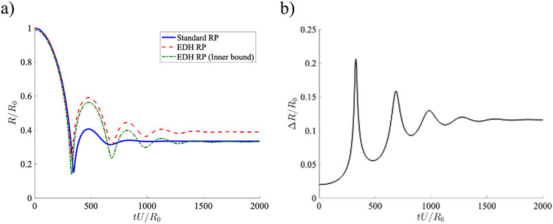
Figure 14. Comparing the evolution of bubble obtained from EDH RP and standard RP. Evolution of (a) bubble radius and (b) interface thickness.
It must be noted that the interface thickness is analytically computed from the initial condition of initial interface thickness and the density sequence (functionality). Hence, in the case of a numerical simulation various fluid and flow properties do no need to be resolved across the interface thickness.
If, in addition to mass conservation, we were to include the momentum conservation of the interface as well, the new RP equation would be (Equation 48).
This is outside of the scope of this paper and will be explored in detail in a future work.
It is asserted that the actual physical front is a diffused region with three dimensions and a finite thickness. Within this region, fluid and flow parameters exhibit sharp but continuous variations across its width. It is important to note that the conventional representation of a front as a hypersurface in continuum theory is a limiting case of this diffused region. As a result, the authors propose a systematic derivation of the dividing surface from the 3D bulk conservation equations that accurately describe this diffused region. This generalized dividing surface is referred to as the extended dividing hypersurface (EDH). The EDH equations are derived by collapsing the dimension across the width of the diffused region, mathematically achieved through integration along its width. This mathematical treatment ensures that the EDH is kinematically and dynamically equivalent to the diffused region, representing the real physical front in its entirety.
6 Conclusion
Gibbs was the first to represent a phase interface by a dividing surface, a mathematical surface that has its own material properties and internal dynamics. In this paper, an alternative derivation of Gibbs’ dividing surface is presented, which generalizes the concept of a dividing surface to fluid fronts beyond those of a phase or material interface. It is asserted that the actual physical front is a diffused region with three dimensions and a finite thickness. Within this region, fluid and flow parameters exhibit sharp but continuous variations across its width. It is important to note that the conventional representation of a front as a hypersurface in continuum theory is a limiting case of this diffused region. As a result, a systematic derivation of the governing equations describing the dividing surface from the 3D bulk conservation equations is proposed in this work. This generalized dividing surface is referred to as the extended dividing hypersurface (EDH). The EDH equations are derived by collapsing the dimension across the width of the diffused region, mathematically achieved through integration along its width. This mathematical treatment ensures that the EDH is kinematically and dynamically equivalent to the diffused region, representing the real physical front in its entirety.
To demonstrate the validity of the EDH model and its generalization, the four canonical problems involving fluid fronts are considered. These problems are (1) stationary fluid with varying miscibility, (2) stratified flow through a converging-diverging section, (3) the shock tube problem, (4) the vortex entrainment sheet, and (5) unsteady bubble dynamics. The selected example problems in this study serve four main purposes within the context of the extended dividing hypersurface (EDH): Firstly, they demonstrate that the EDH can accurately capture the dynamics of not only phase or material interfaces, but also other types of fluid and flow fronts. This highlights the versatility of the EDH in representing a wide range of dynamic phenomena. Secondly, the problems emphasize that the distribution of monotonicity within a front, as commonly described in existing literature, is just one of several possible functionalities that the EDH can effectively represent. This implies that the EDH can offer alternative representations of fluid fronts that may differ from the conventional understanding of monotonicity distribution. Thirdly, the selected problems illustrate the relationship between the flux of
In conclusion, this study establishes the framework for extending Gibbs’ dividing surface by systematically deriving the governing equations. This allows the extension of the dividing surface concept, referred to here as the extended dividing hypersurface (EDH). It demonstrates the capability of the extended dividing hypersurface (EDH) to accurately represent various fluid and flow fronts beyond traditional interfaces. Through the examination of canonical problems, the authors validate the EDH model and its generalization, contributing valuable insights into its ability to capture the dynamics of the front and the surrounding bulk fluid.
Data availability statement
The raw data supporting the conclusions of this article will be made available by the authors, without undue reservation.
Author contributions
JT: Writing – original draft. KM: Writing – review and editing.
Funding
The author(s) declare that financial support was received for the research and/or publication of this article. This research was partially supported by the National Science Foundation, the Office of Naval Research and the South Dakota Board of Regents.
Conflict of interest
The authors declare that the research was conducted in the absence of any commercial or financial relationships that could be construed as a potential conflict of interest.
The handling editor XX declared a past co-authorship with the author KM.
Generative AI statement
The author(s) declare that no Generative AI was used in the creation of this manuscript.
Publisher’s note
All claims expressed in this article are solely those of the authors and do not necessarily represent those of their affiliated organizations, or those of the publisher, the editors and the reviewers. Any product that may be evaluated in this article, or claim that may be made by its manufacturer, is not guaranteed or endorsed by the publisher.
References
1. Mohseni K. Derivation and numerical simulation of regularized (observable) Euler equations. In: Proceedings of the AIAA Aerospace Sciences Meeting; 04-07 January 2010; Orlando, FL, USA (2010). p. 2010–1274. doi:10.2514/6.2010-1274
2. Harlow FH, Amsden AA. Fluid dynamics. A LASL monograph. Los Alamos, NM: Los Alamos National Lab (1971).
3. Saurel R, Abgrall R. A simple method for compressible multi fluid flows. SIAM J Sci Comput (1999) 21:1115–45. doi:10.1137/s1064827597323749
4. Walter C, Sulem C. Numerical simulation of gravity waves. J Comp Phys (1993) 108:73–83. doi:10.1006/jcph.1993.1164
7. Shapiro AH. The dynamics and thermodynamics of compressible fluid flow. New York City, NY, USA: Wiley (1953).
9. Scriven LE. Dynamics of a fluid interface: equation of motion for Newtonian surface fluids. Chem Eng Sci (1960) 12:98–108. doi:10.1016/0009-2509(60)87003-0
10. Slattery JC. Surfaces I. Momentum and moment-of-momentum balances for moving surfaces. Chem Eng Sci (1964) 19:379–85. doi:10.1016/0009-2509(64)80010-5
11. Aris R. Vectors, tensors and the basic equations of fluid mechanics. Englewood Cliffs, NJ, USA: Prentice-Hall (1962).
12. Thalakkottor JJ, Mohseni K. Analysis of boundary slip in a flow with an oscillating wall. Phys Rev E (2013) 87(1–10):033018. doi:10.1103/PhysRevE.87.033018
13. Thalakkottor JJ, Mohseni K. Unified slip boundary condition for fluid flows. Phys Rev E (2016) 94:023113. doi:10.1103/PhysRevE.94.023113
14. Plimpton S. Fast parallel algorithms for short-range molecular dynamics. J Comput Phys (1995) 117:1–19. doi:10.1006/jcph.1995.1039
15. Verlet L. Computer experiments on classical fluids. I. Thermodynamical properties of Lennard-Jones molecules. Phys Rev (2015) 159:98–103. doi:10.1103/physrev.159.98
16. Allen MP, Tildesley DJ. Computer simulation of liquids. 1 edn. England: Clarendon Press Oxford (1987).
17. Rayleigh L. Viii. on the pressure developed in a liquid during the collapse of a spherical cavity. Philos Mag Ser (1917) 6:94–8. doi:10.1080/14786440808635681
18. Plesset M. The dynamics of cavitation bubbles. ASME J Appl Mech (1949) 16:277–82. doi:10.1115/1.4009975
20. Prosperetti A, Tryggvason G. Computational methods for multiphase flow. Cambridge, UK: Cambridge University Press (2007).
21. Thalakkottor JJ, Mohseni K. Role of the rate of surface dilatation in determining microscopic dynamic contact angle. Phys Fluids (2020) 32:012111. doi:10.1063/1.5125231
22. DeVoria AC, Mohseni K. The vortex-entrainment sheet in an inviscid fluid: theory and separation at a sharp edge. J Fluid Mech (2019) 866:660–88. doi:10.1017/jfm.2019.134
23. Xia X, Mohseni K. Unsteady aerodynamics and vortex-sheet formation of a two-dimensional airfoil. JFM (2017) 830:439–78. doi:10.1017/jfm.2017.513
24. Thalakkottor JJ, DeVoria A. Modeling a shock front as an extended dividing hypersurface. In: Aiaa SCITECH. MD: National Harbor (2023). p. 2023–481.
25. Plesset M, Prosperetti A. Bubble dynamics and cavitation. Annu Rev Fluid Mech (1977) 9:145–85. doi:10.1146/annurev.fl.09.010177.001045
26. Brenner M, Hilgenfeldt S, Lohse D. Single-bubble sonoluminescence. Rev Mod Phys (2002) 74:425–84. doi:10.1103/revmodphys.74.425
29. Hung C, Hwangfu J. Experimental study of the behaviour of mini-charge underwater explosion bubbles near different boundaries. J Fluid Mech (2010) 651:55–80. doi:10.1017/s0022112009993776
Keywords: fluid front, computational fluid dynamics, dividing surfaces, multiphase flow (CFD), vortex sheet, shock front
Citation: Thalakkottor J and Mohseni K (2025) Capturing the kinematics and dynamics of fluid fronts. Front. Phys. 13:1652090. doi: 10.3389/fphy.2025.1652090
Received: 23 June 2025; Accepted: 24 July 2025;
Published: 23 October 2025.
Edited by:
Xi Xia, Shanghai Jiao Tong University, ChinaReviewed by:
Hongwei Ning, Anhui Science and Technology University, ChinaChengming He, Jiangsu University, China
Zhenyu Zhang, Beijing Institute of Technology, China
Copyright © 2025 Thalakkottor and Mohseni. This is an open-access article distributed under the terms of the Creative Commons Attribution License (CC BY). The use, distribution or reproduction in other forums is permitted, provided the original author(s) and the copyright owner(s) are credited and that the original publication in this journal is cited, in accordance with accepted academic practice. No use, distribution or reproduction is permitted which does not comply with these terms.
*Correspondence: Joseph Thalakkottor, am9zZXBoLmpvaG50aGFsYWtrb3R0b3JAc2RzbXQuZWR1
 Joseph Thalakkottor
 Kamran Mohseni2,3