 Colin A. Pavan
 Carmen Guerra-Garcia*
- Department of Aeronautics and Astronautics, Massachusetts Institute of Technology, Cambridge, MA, United States
A common platform for studying plasma-assisted ignition and combustion uses a quartz reactor with the plasma applied in a dielectric barrier discharge configuration. The line-of-sight typically used in such a setup, for optical diagnostics and imaging, is transverse to the dominant electric fields. This visualization angle makes the quantification of the dynamic bidirectional interactions between plasma and combustion processes incomplete. Drawing inspiration from the literature on pattern formation in dielectric barrier discharges operated with inert gases, the authors introduce a novel approach: employing transparent indium tin oxide (ITO) electrodes to directly visualize the interaction between a propagating laminar flame and a pulsed nanosecond dielectric barrier discharge. The approach reveals features of the interaction that were previously inaccessible: the discharge alters both the flame’s speed and curvature, while the flame, in turn, impacts the discharge’s uniformity and the motion of microdischarges. This brief research report demonstrates how the use of transparent electrodes in plasma-assisted combustion enhances our ability to explore this complex two-way interaction.
1 Introduction
Plasma-assisted combustion (PAC) technologies are being explored to address various challenging combustion regimes, including lean flammability limit extension [1–3], suppression of dynamic combustion instabilities [4–6], and acceleration of ignition for low-residence time combustion [7, 8]. In many applications, and especially as the technology progresses towards implementation in practical systems, it becomes essential to consider complex combustion environments; this can include turbulence, multi-scale structures, inhomogeneous gases, two-phase flow, propagating flame fronts, etc. It is therefore necessary to understand the two-way interaction of plasmas and flames during combustion transients and when the location of the plasma relative to the flame can vary with time [9–11].
A common experimental platform to study some of these dynamic environments uses a quartz reactor, for optical access, with electrodes attached to the dry-side of the reaction cell (external surface, not in contact with the process gas), so that the discharge actuates in a Dielectric Barrier Discharge (DBD) configuration. Although initially used for its uniform properties to validate chemical kinetic mechanisms [12, 13], the DBD discharge often appears in microdischarge regimes. A similar setup has also been used to study the thermal-chemical instability controlling the transition from a stable homogeneous discharge to unstable microdischarges in different mixtures [14–16]; as well as plasma regime transitions, between uniform and microdischarge modes, during passage of a transient laminar flame [17]. Comparable arrangements have also been used to study plasma-assisted detonation [18, 19]. In all of these works, imaging and optical diagnostics of discharge and combustion is performed through the narrow side of the discharge cell, with the line-of-sight contained in a plane parallel to the flat electrodes. This view-angle hinders the quantification of several properties of plasma and combustion, including: the volumetric density of microdischarges present in the cell, as well as the 2D or 3D plasma and combustion dynamics beyond a spatially-integrated 1D representation.
The objective of this brief research report is to showcase a novel imaging technique that allows for the direct observation of 2D interactions between a propagating flame front and microdischarges triggered by Nanosecond Repetitively Pulsed (NRP) dielectric barrier discharges (DBD). The imaging is enabled by the use of transparent electrodes arranged orthogonal to the flame front plane, with a camera mounted to view along the axis of the applied electric field. Several complex interactions between the flame and plasma are revealed that were hidden in prior studies visualizing the interaction from the side. Although the use of transparent electrodes has been common in DBD research, particularly to study DBD uniformity and patterning [20–22], when used in a system combining a DBD with a flame front they allow for studying both the structure of the DBD and the flame, and how they interact with one another.
2 Methods
A schematic of the experimental setup is shown in Figure 1. It consists of a tapered quartz burner fed with premixed methane-air mixtures that has been previously described in [17]. The mixture enters at the narrow end of the channel at below the flame speed and is ignited at the wide end via a conventional spark plug, causing a flame to flash back through the channel before being quenched by the narrowing walls. The reactor is open to atmospheric pressure at the wide end and its dimensions are given in Figure 1. In the absence of plasma, the flame has a one or two-lobe structure, in the x-y plane, as a consequence of the finite channel dimensions and the development of fluid instabilities; this is thought to be a tulip-flame structure [23, 24]. Electrodes are mounted on the dry walls of the channel (external surface, not in contact with the process gas, Figure 1) so as to apply an electric field in the z-direction and a NRP DBD is triggered as the flame approaches the discharge volume. The ground electrode is an aluminum plate that spans the length of the reactor. The powered electrode is a glass slide of 1 mm thickness coated on the external side with a thin film of Indium Tin Oxide (ITO). High voltage is applied using a nanosecond pulse generator (Transient Plasma Systems SSPG-20X-HP1). The ITO electrode is transparent, allowing the camera to be positioned to view along the z-direction (see Figure 1) which is aligned with the dominant electric fields and the axis of any microdischarges forming.

Figure 1. Experimental setup. Drawing not to scale. Quartz walls are 2 mm thick and the electrode labeled ITO is a 1 mm thick glass slide with a 185 nm nominal thickness coating of ITO on the side not in contact with the quartz (referred to as the dry side). In the y-direction, the reactor is 30 mm wide.
Experimental parameters are chosen as follows. The applied voltage pulses have an applied peak voltage measured at the load of 22.5 kV and are repeated at frequencies up to 8 kHz. Trains of pulses are applied continuously with the start of the pulse-train synchronized with the triggering of the flame front, at variable delays. Premixed methane/air mixtures at an equivalence ratio of 1.06 (close to stoichiometric) are used, with a total flow rate of 400sccm.
Imaging is performed using high-speed videography. Two cameras are used: a Photron Fastcam Mini AX100 is used for the colour images, Figure 2, and an Edgertronic SC2+ is used for the monochrome images used to quantify flame and microdischarge dynamics, Figures 4, 6. Color images allow for visual separation of the flame (blue) and discharge (violet) to distinguish the different structures which may be overlapping. Monochrome images have greater luminosity and allow for higher frame rates, up to the point where the camera frame rate is twice the pulse repetition rate which allows for alternating frames of flame only and flame plus discharge. This provides an alternate method of distinguishing flame from discharge and enables flame front and microdischarge tracking.
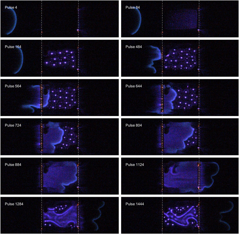
Figure 2. Color images of a mesoscale flame interacting with a nanosecond pulsed DBD. Flame travels left to right and view is along the direction of the main electric field. Dashed white lines mark the edges of the transparent electrode (50 mm long). Each image integrates the light from 4 sequential pulses, with the last of these pulses indicated by the label. Pulse repetition frequency 8kHz, 22.5 kV peak voltage (measured at load). CH4/air premixed flame (equivalence ratio 1.06) at ambient temperature/pressure.
3 Results and discussion
Several images from a single test are shown in Figure 2 with test conditions given in the caption. The images show a flame approaching the discharge region from the left. Before the flame reaches the inter-electrode gap, the discharge is turned on and initially takes a uniform appearance. As the pulses accumulate, the discharge transitions to microdischarges. While the flame is inside the discharge volume, a uniform discharge exists in the burned gas, while microdischarges persist ahead of the flame. The flame front is considerably more wrinkled than it was prior to reaching the discharge volume. After the flame leaves the discharge volume, the discharge transitions back to microdischarges, with a uniform discharge persisting in regions of higher gas temperature. The use of the transparent electrodes enables several observations that were not possible previously with a conventional camera view along the y-axis (see [17]). A couple of novel observations, enabled by the ITO electrodes, are briefly discussed in the following paragraphs, with a quantitative analysis left to a future work.
3.1 Plasma impacting flame: enhanced wrinkling and local acceleration
First, the impact of plasma on flame is manifested as a local acceleration of the flame front, accompanied by enhanced flame wrinkling. Prior work [25–27] has demonstrated the impact of plasma on the magnitude of the flame speed. The use of transparent electrodes reveals the inhomogeneous impact of the plasma on the flame front. Prior to reaching the discharge region, the leading edge of the flame encounters the gas pre-treated by the plasma and accelerates towards the discharge volume. This causes local stretching of regions of the flame, and is visible in Figure 2 in the image labeled “pulse 484”. This illustrates that different portions of the flame front will experience different interactions with the plasma dependent on their location relative to the discharge; for a non-planar flame the portion closest to the discharge will be most strongly impacted by it. Once the flame has entered the discharge volume, the non-uniformity of the discharge has an impact on the flame propagation. Regions of the flame front that are near a microdischarge will accelerate into the microdischarge, while regions far from any microdischarges will lag behind. This can be observed in Figure 2, between pulses 644 and 724; the top portion of the flame is close to two microdischarges and accelerates to meet them, while the bottom portion is further from the microdischarges and does not accelerate. The inhomogenous discharge causes significant wrinkling in the flame front, Figure 2. The impact of plasma on flame speed increase and flame wrinkling is highlighted in Figures 3, 4, which compare a case without plasma and a case with plasma. First, the flame contours (plotted every 6 ms) become spaced further apart in the region of interaction with the plasma, indicating a flame speed acceleration. In the present experiment, the average flame speed increase is 50% that of the no-plasma baseline. In addition, as the flame front approaches, and crosses under the electrode, it becomes significantly more distorted due to the effect of the discharge on the flame. This effect can be quantified by calculating the curvature, which approximately doubles from 0.15 mm−1, for no plasma, to 0.3 mm−1, in the region where plasma is applied. The total length of the flame front also increases by 25%–50% in the region of plasma-assistance. Further details of the flame tracking analysis and curvature calculation can be found in [28]. Note that the flame speed increase is due to the combined effect of the thermal-kinetic enhancement of the plasma as well as the greater surface area caused by the wrinkling.

Figure 3. Flame front position at 6 ms increments, with color changing from blue at earlier times to green at later times. Flame is traveling from left to right and the dashed black lines indicate the edges of the electrode. No discharge is applied. x-y view.
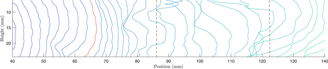
Figure 4. Flame front position at 6 ms increments, with color changing from blue at earlier times to green at later times. Flame is traveling from left to right. The red contour is the flame location when the discharge is first turned on and the dashed black lines indicate the edges of the electrode. x-y view.
The use of transparent electrodes enables top-view imaging, which is needed to capture the geometrical structure and dynamics of the flame front. In flames with multiple lobes, the top view captures the complete spatial variation along the front, whereas the side view often shows only the leading edge or appears as a thickened, split structure (Figure 5A). This distinction is especially important for accurately estimating flame speed. Top-view imaging allows for the extraction of spatially resolved velocity vectors in the x-y plane (Figure 4), while the side view emphasizes the most advanced point, potentially leading to overestimation. This difference becomes especially important with plasma actuation, where the maximum flame tip velocity and the average along the full contour diverge substantially. For example, in the configuration used for the frames in Figure 5, the plasma-activated flame exhibits a maximum flame speed of 80 cm/s locally, compared to a spatial average of approximately 40 cm/s. Relying only on side-view imaging would obscure this variation. Furthermore, the fastest moving point of the flame is not always the furthest point as the stretched flame can result in regions behind the leading edge having the fastest speed as they “catch up.” Moreover, the top-view perspective enables accurate quantification of flame front length and curvature, given its thin luminous profile. In contrast, the side view integrates information along the line of sight. In regions near the electrode, side-view imaging underestimates deformation and complexity of the flame structure, Figure 5A.
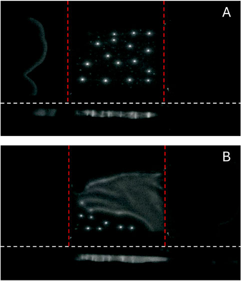
Figure 5. Simultaneous imaging of the plasma-flame interactions from top view and side view, imaged using a mirror and a single camera, highlighting some of the additional information the transparent electrode brings. For each figure, the top view is above the white dashed line and the side view is below. Red lines indicate the electrode edge. (A) Proper flame front identification for multi-lobe morphology. (B) Demonstration of spatially-decoupling the microdischarges and the uniform discharge.
3.2 Flame impacting plasma: multi-regime topology and microdischarge motion in flow field
Next, when considering the impact of flame on plasma, both the multi-regime topology and the motion of microdischarges in the flow field become apparent. The two-regime behavior includes inhomogeneous microdischarges far ahead of the flame, and a homogeneous uniform discharge coupled to the hot burned gases. This was observed in prior work and associated with changing temperature, flow speed and chemistry across the flame front [17]. Notably, the return to microdischarges shortly after flame passage - despite the gas still being hot - suggests that temperature alone does not govern the regime transition; and that the accumulated effects of many pulses change the dynamics of the transition. As discussed in [9, 17], additional factors such as changes in gas composition (e.g., NO and water), surface charge memory, and the interplay between flow residence time and pulse repetition rate can influence the onset of filamentation in the post-flame zone. It may also be that chemi-ionization produced by the flame front contributes to homogenizing the discharge [9].
In the wake of the flame, the transition from the uniform discharge to microdischarges occurs locally near the walls of the channel and gradually expands throughout the discharge region. Individual microdischarges suppress uniform discharge in a local region around them (see pulse 1444 in Figure 2). In the wake of the flame, the discharge resembles the hybrid structure seen in pure DBD setups without combustion [21]. One key advantage of the transparent electrode is that it eliminates the spatial integration inherent in side-view imaging. Figure 5B shows simultaneous top and side views of the discharge-flame interaction, captured using a mirror and a single camera. Although the side view produces a spatially integrated image that cannot resolve the spatial separation of temporally coexisting features, the top view reveals that the microdischarges and the uniform discharge, though concurrent in time, are distinctly separated in the spanwise direction.
A less obvious effect is the motion of the microdischarges in the flow field created by the background gas and flame front. This is shown in Figure 6. For each frame in a sequence, a single iso-brightness contour is shown, which highlights the reaction front and the main microdischarges. The contours are colored according to the time of the frame. Looking at the microdischarges, all initially travel towards the flame front (from right to left). At around 180 ms, all the discharge channels disappeared due to their contact with the flame front or changed their direction and begin to travel away from the flame front, in a direction roughly normal to it. The initial motion from right to left is driven by the flow of gas. The later motion away from the flame front is caused by the flame front itself. The cause will be investigated in detail in future works, but possible explanations are a local reversal of flow direction caused by the hot gases expanding in a confined channel behind the flame front or the uniform discharge behind the flame front interacting electrostatically with the microdischarge.

Figure 6. Iso-brightness contours taken from high speed video; each color corresponds to a single frame in the video as indicated. The small closed contours on the right are individual microdischarges and the elongated contours on the left are the reaction front moving from left to right. Dashed black lines show the edges of the electrodes.
4 Conclusion
In conclusion, a mesoscale channel-burner was used to investigate the interaction between a propagating premixed laminar flame front and an NRP DBD. The use of transparent ITO electrodes facilitated a comprehensive evaluation of the bidirectional interactions between the plasma and the flame. The discharge was observed to alter flame propagation by locally accelerating it and changing its geometry, through curvature and surface area increases. Simultaneously, the flame influenced the uniformity of the discharge and the overall motion of the microdischarges. Recognizing and quantifying this two-way interaction is key to the design of plasma-assisted combustion systems, particularly those involving propagating flame fronts and in-situ plasma. The use of transparent electrodes in plasma assisted combustion, ignition and detonation, opens up an opportunity to visualize and quantify 2D and 3D features of the interaction that were previously inaccessible, when using a viewpoint orthogonal to the electric field direction.
Data availability statement
The raw data supporting the conclusions of this article will be made available by the authors, without undue reservation.
Author contributions
CP: Data curation, Formal Analysis, Methodology, Investigation, Writing – original draft, Visualization. CG-G: Project administration, Methodology, Conceptualization, Writing – original draft, Resources, Funding acquisition, Formal Analysis, Supervision.
Funding
The author(s) declare that financial support was received for the research and/or publication of this article. This work was supported by the Office of Naval Research (ONR), under Award Number N00014-21-1-2571. CP acknowledges funding through a Mathworks Fellowship.
Acknowledgments
The authors would like to thank J. Bales from the MIT Edgerton Center for loaning his Photron camera for these experiments and training on its use.
Conflict of interest
The authors declare that the research was conducted in the absence of any commercial or financial relationships that could be construed as a potential conflict of interest.
Generative AI statement
The author(s) declare that no Generative AI was used in the creation of this manuscript.
Any alternative text (alt text) provided alongside figures in this article has been generated by Frontiers with the support of artificial intelligence and reasonable efforts have been made to ensure accuracy, including review by the authors wherever possible. If you identify any issues, please contact us.
Publisher’s note
All claims expressed in this article are solely those of the authors and do not necessarily represent those of their affiliated organizations, or those of the publisher, the editors and the reviewers. Any product that may be evaluated in this article, or claim that may be made by its manufacturer, is not guaranteed or endorsed by the publisher.
References
1. Barbosa S, Pilla G, Lacoste DA, Scouflaire P, Ducruix S, Laux CO, et al. Influence of nanosecond repetitively pulsed discharges on the stability of a swirled propane/air burner representative of an aeronautical combustor. Philos T R Soc A (2015) 373:20140335. doi:10.1098/rsta.2014.0335
2. Di Sabatino F, Lacoste DA. Enhancement of the lean stability and blow-off limits of methane-air swirl flames at elevated pressures by nanosecond repetitively pulsed discharges. J Phys D Appl Phys (2020) 35:355201. doi:10.1088/1361-6463/ab8f54
3. Bak MS, Do H, Mungal MG, Cappelli MA. Plasma-assisted stabilization of laminar premixed methane/air flames around the lean flammability limit. Combust Flame (2012) 159:3128–37. doi:10.1016/j.combustflame.2012.03.023
4. Shanbhogue SJ, Pavan CA, Weibel DE, Gomez del Campo F, Guerra-Garcia C, Ghoniem AF. Control of large-amplitude combustion oscillations using nanosecond repetitively pulsed plasmas. J Propul Power (2023) 39:469–81. doi:10.2514/1.b38883
5. Moeck J, Lacoste D, Laux C, Paschereit C. Control of combustion dynamics in a swirl-stabilized combustor with nanosecond repetitively pulsed discharges. In: 51st AIAA aerospace Sciences Meeting including the new Horizons forum and Aerospace exposition. Reston, Virigina: American Institute of Aeronautics and Astronautics (2013). p. 565.
6. Kim W, Cohen J. Plasma-Assisted combustor dynamics control at realistic gas turbine conditions. Combust Sci Technol (2021) 193:869–88. doi:10.1080/00102202.2019.1676743
7. Do H, Cappelli MA, Mungal MG. Plasma assisted cavity flame ignition in supersonic flows. Combust Flame (2010) 157:1783–94. doi:10.1016/j.combustflame.2010.03.009
8. Do H, Im SK, Cappelli MA, Mungal MG. Plasma assisted flame ignition of supersonic flows over a flat wall. Combust Flame (2010) 157:2298–305. doi:10.1016/j.combustflame.2010.07.006
9. Guerra-Garcia C, Pavan CA. The backward problem in plasma-assisted combustion: experiments of nanosecond pulsed discharges driven by flames. Appl Energ Combustion Sci (2023) 15:100155. doi:10.1016/j.jaecs.2023.100155
10. Leonov SB, Adamovich IV, Soloviev VR. Dynamics of near-surface electric discharges and mechanisms of their interaction with the airflow. Plasma Sourc Sci T (2016) 25:063001. doi:10.1088/0963-0252/25/6/063001
11. Leonov BS, Hedlund B, Houpt A. Morphology of quasi-direct-current discharges collocated with fuel jets in a supersonic crossflow. J Propul Power (2020) 36:508–16. doi:10.2514/1.b37555
12. Adamovich IV, Nishihara M, Choi I, Uddi M, Lempert WR. Energy coupling to the plasma in repetitive nanosecond pulse discharges. Phys Plasmas (2009) 16:113505. doi:10.1063/1.3264740
13. Adamovich IV, Choi I, Jiang N, Kim JH, Keshav S, Lempert WR, et al. Plasma assisted ignition and high-speed flow control: Non-thermal and thermal effects. Plasma Sourc Sci Technology (2009) 18:034018. doi:10.1088/0963-0252/18/3/034018
14. Zhong H, Shneider MN, Mao X, Ju Y. Dynamics and chemical mode analysis of plasma thermal-chemical instability. Plasma Sourc Sci T (2021) 30:035002. doi:10.1088/1361-6595/abde1c
15. Zhong H, Shneider MN, Mokrov MS, Ju Y. Thermal-chemical instability of weakly ionized plasma in a reactive flow. J Phys D Appl Phys (2019) 52:484001. doi:10.1088/1361-6463/ab3d69
16. Rousso AC, Goldberg BM, Chen TY, Wu S, Dogariu A, Miles RB, et al. Time and space resolved diagnostics for plasma thermal-chemical instability of fuel oxidation in nanosecond plasma discharges. Plasma Sourc Sci T (2020) 29:105012. doi:10.1088/1361-6595/abb7be
17. Pavan CA, Guerra-Garcia C. Nanosecond pulsed discharge dynamics during passage of a transient laminar flame. Plasma Sourc Sci T (2022) 31:115016. doi:10.1088/1361-6595/aca0bc
18. Shi Z, Mao X, Thawko A, Ju Y. Numerical modeling of plasma assisted deflagration to detonation transition in a microscale channel. Proc Combustion Inst (2024) 40:105659. doi:10.1016/j.proci.2024.105659
19. Lafaurie V, Shu Z, Vidal P, Starikovskaia S. Gradient pulsed transient plasma for initiation of detonation. Combustion and Flame (2024) 261:113311. doi:10.1016/j.combustflame.2024.113311
20. Duan X, He F, Ouyang J. Uniformity of a dielectric barrier glow discharge: experiments and two-dimensional modeling. Plasma Sourc Sci T (2012) 21:015008. doi:10.1088/0963-0252/21/1/015008
21. Callegari T, Bernecker B, Boeuf JP. Pattern formation and dynamics of plasma filaments in dielectric barrier discharges. Plasma Sourc Sci T (2014) 23:054003. doi:10.1088/0963-0252/23/5/054003
22. Raizer YP, Mokrov MS. Physical mechanisms of self-organization and formation of current patterns in gas discharges of the Townsend and glow types. Phys Plasmas (2013) 20:101604. doi:10.1063/1.4823460
23. Clanet C, Searby G. On the “tulip flame” phenomenon. Combust Flame (1996) 105:225–38. doi:10.1016/0010-2180(95)00195-6
24. Gonzalez M, Borghi R, Saouab A. Interaction of a flame front with its self-generated flow in an enclosure: the “tulip flame” phenomenon. Combust Flame (1992) 88:201–20. doi:10.1016/0010-2180(92)90052-q
25. Pavan CA, Guerra-Garcia C. Modeling flame speed modification by nanosecond pulsed discharges to inform experimental design. In: AIAA SCITECH 2023 Forum. Reston, Virginia: American Institute of Aeronautics and Astronautics (2023).
26. Elkholy A, Shoshyn Y, Nijdam S, van Oijen JA, van Veldhuizen EM, Ebert U, et al. Burning velocity measurement of lean methane-air flames in a new nanosecond DBD microplasma burner platform. Exp Therm Fluid Sci (2018) 95:18–26. doi:10.1016/j.expthermflusci.2018.01.011
27. Lacoste DA. Flames with plasmas. P Combust Inst (2023) 39:5405–28. doi:10.1016/j.proci.2022.06.025
Keywords: transparent electrodes, indium tin oxide (ITO), plasma-assisted combustion (PAC), nanosecond pulsed discharge (NPD), dielectric barrier discharge (DBD), laminar flame speed
Citation: Pavan CA and Guerra-Garcia C (2025) Imaging of dynamic plasma-combustion interactions through a transparent electrode. Front. Phys. 13:1654714. doi: 10.3389/fphy.2025.1654714
Received: 26 June 2025; Accepted: 21 August 2025;
Published: 23 September 2025.
Edited by:
Gabi Daniel Stancu, Université Paris-Saclay, FranceReviewed by:
Nicolas Minesi, Université Paris-Saclay, FranceCiprian Dumitrache, Colorado State University Libraries, United States
Copyright © 2025 Pavan and Guerra-Garcia. This is an open-access article distributed under the terms of the Creative Commons Attribution License (CC BY). The use, distribution or reproduction in other forums is permitted, provided the original author(s) and the copyright owner(s) are credited and that the original publication in this journal is cited, in accordance with accepted academic practice. No use, distribution or reproduction is permitted which does not comply with these terms.
*Correspondence: Carmen Guerra-Garcia, Z3VlcnJhY0BtaXQuZWR1