 Arnab Ghosh1
 Alessandro Gabbana
 Herman J. H. Clercx
  Federico Toschi
- 1Department of Applied Physics and Science Education, Fluids and Flows Group and J.M. Burgers Centre for Fluid Dynamics, Eindhoven University of Technology, Eindhoven, Netherlands
- 2Department of Physics and Earth Science, University of Ferrara and INFN Ferrara, Ferrara, Italy
- 3Los Alamos National Laboratory, CCS-2 Computational Physics and Methods, Los Alamos, NM, United States
- 4Los Alamos National Laboratory, Center for Nonlinear Studies (CNLS), Los Alamos, NM, United States
- 5Canon Production Printing Netherlands B.V., Venlo, Netherlands
- 6Consiglio Nazionale delle Ricerche - Istituto per le Applicazioni del Calcolo, Rome, Italy
The dynamics of finite-sized particles in fluids, and their influence on the overall flow, are of great interest across several industrial, environmental, and medical fields. In the context of inkjet printing, the presence of solid inclusions can be either intentional, as in additive manufacturing, or unintentional, as in standard printing processes. These inclusions can strongly impact the jetting process, causing effects such as jet asymmetry, bubble entrapment, and the formation of satellite droplets. Understanding and controlling particle behavior is therefore essential, particularly to predict how and when particles are ejected over multiple jetting cycles. It is therefore critical to develop reliable models that allow for a deeper understanding of the complex interplay between particle and fluid during the whole printing process. To address this, we present a tailored implementation of the Color-Gradient multicomponent Lattice Boltzmann Method for fully resolved three-dimensional (3D) simulations of multicycle liquid jetting with particles. Our method supports realistic parameter settings aligned with industrial inkjet systems, and we provide both qualitative and quantitative validation against experimental data. Additionally, we introduce a simplified model based on the Stokes drag law, in which solid particles are represented as point particles and do not influence the fluid flow. Despite this limitation, the model offers a computationally efficient means to explore the vast parameter space typically encountered in industrial applications, allowing, e.g., identifying critical ejection regions and estimating the number of cycles required for particle release. These qualitative insights are valuable for guiding and complement fully two-way coupled simulations.
1 Introduction
Today, the application of liquid jetting is widespread in various industrial sectors, ranging from traditional printing technology [1] to additive manufacturing [2], with new applications constantly emerging. Beyond conventional uses, droplet-based deposition is now being applied or explored in three-dimensional (3D) printing of large-scale structures such as houses and bridges [3], fabrication of complex resin and polymer geometries [4], production of electronic circuit boards [5], solar cells [6], and microlenses [7]. This technology also finds application in additive manufacturing with molten metals [8], in the printing of living organic tissue and organs such as the cornea and ears [9] and the production of aerospace components, including parts for satellites and rocket engines [10]. In all of these applications, fluids are deposited layer-by-layer onto a substrate, using various jetting techniques and fluid compositions.
These fluids often contain dispersed solid inclusions, either by design, when particles are the functional components being printed, or as unintended contaminants. In both scenarios, understanding the dynamics of particles during jetting and their effect on flow behavior is critical, requiring a combined experimental and computational approach.
Experimental investigations can be costly and time-consuming, especially due to the difficulty of visualizing flow and particle motion within confined geometries at micrometer scales, making reliable 3D numerical models essential for understanding particle dynamics and droplet formation.
We focus on drop-on-demand (DoD) liquid inkjet printing, which is often favored in industry due to its fine control over droplet generation and the potential for cost reduction relative to continuous inkjet (CIJ) printing [1, 12]. Although our study emphasizes DoD systems, our approach is general and can be extended to the modeling of 3D additive manufacturing of different composite materials.
Figure 1 shows a cross-sectional sketch of a typical DoD jetting system (printhead) along with an indication of the domain studied and an example of a solid inclusion. For inkjet printing, typical droplet diameters are about 20 μm, with ejection velocities ranging from 5 to 10 m/s [1, 12]. Solid inclusions encountered in industrial settings generally range from 5 to 12 µm in size, with a particle-to-fluid density ratio of approximately
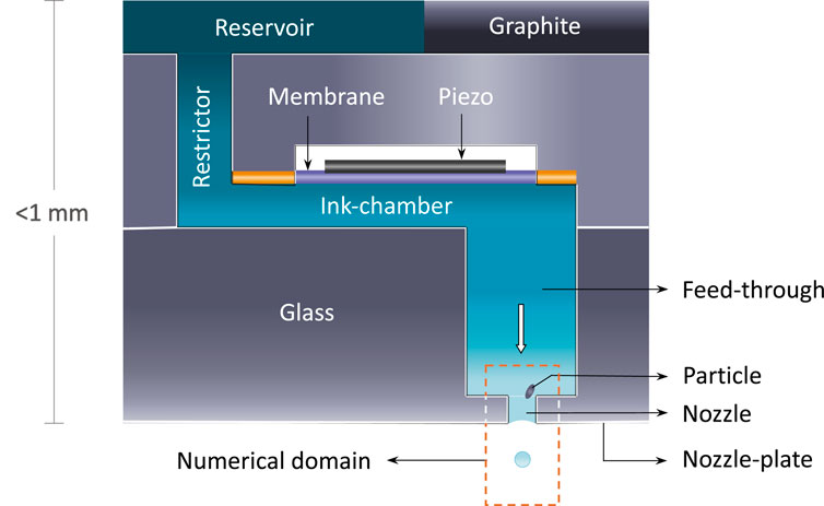
Figure 1. Cross-section schematic of a drop-on-demand (DoD) printhead. A voltage pulse drives the piezoelectric membrane to vibrate, perturbing the ink in the ink-chamber/reservoir. The resulting pressure forces ink through the feed-through and out of the nozzle, forming a droplet attached to the meniscus by a long ligament. Subsequently the droplet pinches off, and the ligament contracts into a spherical shape. The rectangular box bounded by dashed orange lines marks the domain of interest for our numerical simulations.
In Figure 2a we show a typical experimental droplet formation process during an inkjet cycle in the ideal scenario, i.e., in the absence of solid inclusions in the nozzle. In contrast, Figure 2b illustrates how the presence of a solid particle perturbs this process. As droplet sizes become more irregular, satellite droplets become more frequent, and the jetting direction deviates from the nozzle’s symmetry axis. As a consequence the ejection process becomes fully non-axisymmetric, thus requiring fully 3D simulations to accurately capture and analyze the dynamics involved.
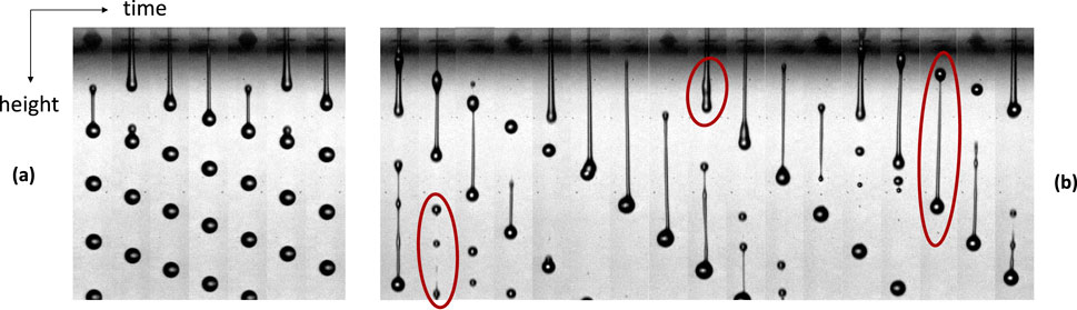
Figure 2. (a) Droplet formation during jetting without solid particles (ideal case). (b) Jetting with solid particles inside the nozzle, creating asymmetry and generating satellite droplets. Images provided by Tim Seegers [11].
While various numerical methods, such as the Arbitrary Lagrangian Eulerian Finite Element Method (ALE-FEM) [13, 14] and the Volume of Fluid (VOF) method [15, 16], have been proposed to simulate liquid jetting, many prior models assume axisymmetric geometries for computational efficiency. Although valid for ideal cases, this assumption fails in the presence of particles and cannot capture the associated flow asymmetries. To overcome this limitation, we have developed a fully parallel 3D Lattice Boltzmann Method (LBM), based on a multi-component Color-Gradient (CG) formulation [17–19], for the simulation of ink-jetting. The model is coupled with the moving boundary bounce-back (MBB) scheme [20–22] to allow the description of fluid-particle interactions. One of the objectives of this work is to test whether this numerical setup is suitable for studying ink-jet printing under realistic industrial scenarios, by comparing both qualitatively and quantitatively with experimental data. To give an example, in Figure 3 we present cross-sectional views of jetting with and without a solid particle from numerical simulations, showing how the particle deflects the jetting angle and affects the droplet trajectory, with the induced disturbances qualitatively matching the experimental observations in Figure 2.
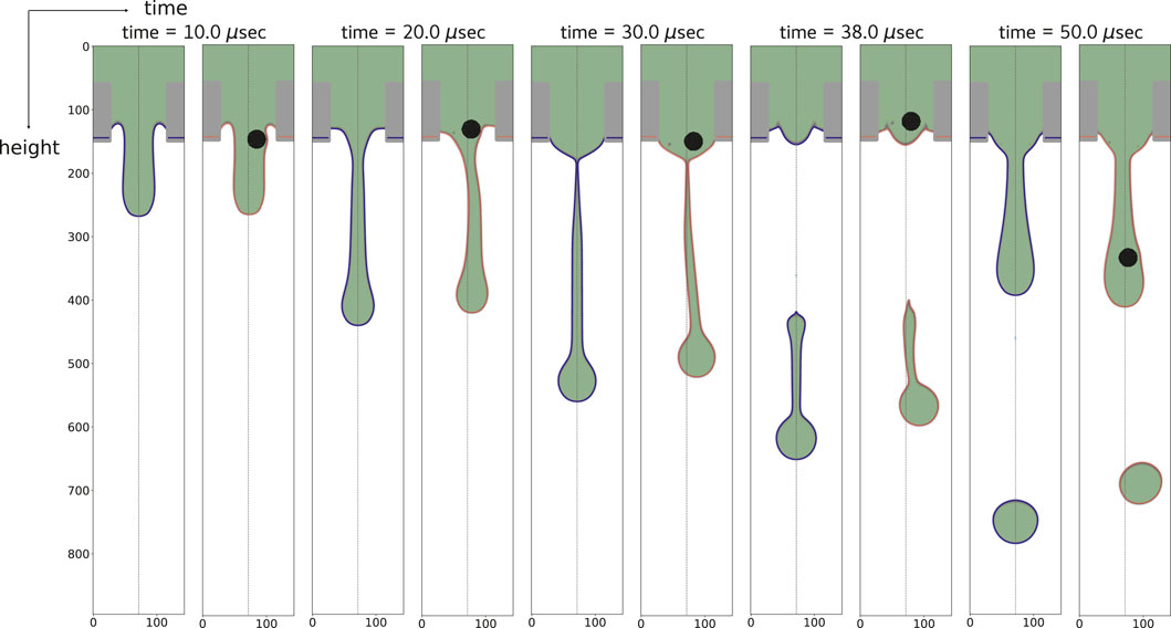
Figure 3. Side-by-side comparison of liquid jetting with and without a solid particle (black sphere) inside the nozzle. Red contours show the ink-air interface with a particle; blue represents the ideal case. The particle induces asymmetry in droplet formation and causes angled ejection. Particle diameter:
Fully two-way coupled simulations, while technically feasible, come with relatively high computational cost, which can limit their use in large-scale investigations of the vast parameter range encountered in industrial applications. The cost of modeling fluid-particle interactions across various particle sizes, shapes, and initial positions makes this approach challenging, particularly when access to high-performance computing resources is limited. On the other hand, one-way coupled models are often sufficient to address simpler yet relevant questions within industrial applications such as, for example, predicting the dynamics and ejection times of solid inclusions released in the feed-through or nozzle.
To address this, we take a first step towards the definition of a one-way coupled heavy-particle model designed to accurately evolve the dynamics of particles in the feed-through and the nozzle. The heavy-particle model implies particles with a particle-to-fluid density ratio
Neglecting the feedback of particle motion on the fluid makes the model a reasonable simplification when only one or a few inclusions are present, makes the model computationally efficient (on par with single-phase fluid simulations), offering a powerful exploratory tool for investigating the qualitative behavior of particles in jetting flows. It enables rapid exploration of the parameter space by adding millions of particles without affecting the flow, helping to identify key features such as the regions within the nozzle and feed-through where particle ejection is most likely, as well as estimating the number of jetting cycles needed for particle expulsion.
We envision applying this model within a V-cycle framework: The process begins with fully resolved two-way coupled simulations, which are used for the calibration of the heavy-particle model. Once this is established, the one-way coupled model can be employed to explore a broader parameter space efficiently. Finally, the insights gained from this qualitative exploration will guide more targeted high-fidelity two-way coupled simulations.
This article is organized as follows. In Section 2, we provide a brief overview of the numerical methodology, covering the LBM, the CG formulation for multicomponent flow, and the numerical integration of fully resolved particles. In Section 3, we present our simulation results for particle dynamics using both fully resolved particles and the heavy-point-particle model. Finally, Section 4 summarizes our findings and discusses future directions.
2 Methodology
In this section, we discuss the mathematical formulation of the equations of motion and the forces governing the combined dynamics of the fluid and suspended particles during liquid jetting.
2.1 Particle dynamics in fluid flows
The fundamental equations that describe the hydrodynamics of viscous fluid flows are the Navier-Stokes (NS) equations [27], which, for an incompressible Newtonian fluid (with
Here,
where
The flow field around a particle can be characterized by the particle Reynolds number, which quantifies the ratio of inertial to viscous forces acting on the particle due to the surrounding fluid motion,
where
The equation of motion for fluid and particles, Equations 1, 2, respectively, cannot be solved analytically, in general. We employ numerical methods based on LBM [28–30] coupled with the CG method [18, 31, 32] to simulate the fluid flow with the ink-air interaction. The dynamics of the particle is solved through the implementation of a two-way coupled fluid-particle interaction model called the MBB scheme [20–22].
2.2 Color-gradient LBM with central moments
We provide a brief overview of the main features of the Central Moments (CM) Color Gradient (CG) LBM used for our numerical simulations.
The CG method is one of the earliest approaches for modeling multicomponent fluids with LBM. It was introduced by Gunstensen et al. [33], after which several important modifications and improvements were proposed. Leclaire et al. [19, 32], who extended the local equilibrium with additional terms, introduced a major improvement in accuracy. Moreover, the adoption of the CM formulation by De Rosis et al. [17, 18] significantly increases the stability range of simulations (allowing significantly larger density ratios of the fluid components).
We consider a multicomponent fluid and describe the time evolution of its
where
Table 1. List of discrete velocities
Macroscopic quantities are defined as the velocity moments of lattice populations. The total density
The total momentum is given by
The CG method evaluates the collision operator
Each suboperator in Equation 8 represents a distinct physical mechanism. The single-phase collision is modeled using the BGK operator [34],
where
The equilibrium distribution
The weights
The perturbation operator
After the collision step, streaming is applied,
Previous studies have compared different multiphase LBM models, such as the Color Gradient and pseudopotential models (e.g., Shan-Chen), in terms of accuracy and stability [19, 36], finding that the CG model outperforms the Shan-Chen approach, both in terms of accuracy and stability.
In particular, the CG model demonstrated significantly better numerical stability at high fluid-fluid density ratios, of the order of
2.3 Boundary conditions
The boundary conditions used in the numerical setup depicted in Figure 1 include both conventional and advanced schemes to ensure stable and accurate simulations. A standard no-slip bounce-back condition is imposed on the solid walls of the nozzle. Inflow and outflow boundaries are treated with appropriate schemes to enforce prescribed macroscopic field profiles and suppress nonphysical pressure reflections from the domain boundaries. To model interfacial phenomena at the ink-air interface in contact with solid surfaces, wetting boundary conditions are implemented. Furthermore, the interaction between the fluid and fully resolved moving particles is captured through a two-way coupled approach, employing the MBB method to account for the dynamics of curved time-evolving boundaries. The reader is referred to the Supplementary Material for full details on the implementation of the different boundary conditions for the current flow configuration.
2.4 Time evolution of particle dynamics
The time evolution of particle dynamics in terms of position, orientation, as well as translational and angular velocity, is governed by Newton’s laws of motion (Equations 2, 3). The translational force balance acting on the particle is given by
where
Rotational motion is governed by the torque balance,
where
We perform the time integration of the above equations employing the well-known leap-frog algorithm [42].
The target velocity on the particle surface can be calculated by combining the translational and angular velocities,
Finally, to update the orientation of the particle, we employ a quaternion-based representation [42, 43].
2.5 Modeling of heavy-point-particle dynamics
Numerically investigating liquid jetting with solid inclusions is often computationally unfeasible, due to the high costs associated with fully resolved 3D two-way coupled simulations and the vast parameter space typically encountered in industrial applications. Therefore, we also introduce one-way coupled simulations of solid particles in liquid jetting.
Our starting point is the Maxey-Riley (MR) equation [26], which is commonly used [44–46] for approximating the motion of a spherical particle in a fluid flow. Generally, this equation can be used when the particle size is much smaller than the length scale of the flow, and
For particles with density ratios
where
Similar phenomenological equations are needed for the angular dynamics of a point particle in our liquid jetting application. We assume that the local shear rate of the (unsteady) laminar flow in the feed-through and nozzle is, to good approximation, uniform on the particle scale. As a simplified model, we employ the solution of angular orientation and angular velocity of a spheroidal particle in uniform and steady shear flow as given by Jeffery in 1922 [52]. The original solution assuming a constant shear rate,
with
where
3 Numerical results
This section presents the results of our numerical analysis based on the methods outlined in Section 2. A validation of our implementation of the CM-CG LBM and the boundary condition schemes, which enable accurate capture of fluid-particle interactions, is provided in the Supplementary Material.
In Section 3.1 we examine the dynamics of a particle during the jetting process under realistic conditions, comparing the simulation results with the experimental data extracted from video recordings. In Section 3.2, we investigate the effects of particle size and shape on their dynamics during a single jetting cycle. Finally, in Section 3.3, we discuss scenarios in which a one-way coupled approach can be used as a computationally cheap, yet reliable, alternative.
3.1 Liquid jetting with a solid particle: qualitative comparison with experimental data
We simulate the dynamics of a fully resolved particle during a jetting cycle, testing our numerical setup with realistic parameters [53]. We qualitatively compared our numerical results with data extracted from high-speed video recordings of actual experiments (cf. Figure 2).
In Figure 4a we provide a sketch of the numerical setup, showing a particle with initial position in the feed-through in proximity of the nozzle. To guide our analysis, we place the origin of the axes,
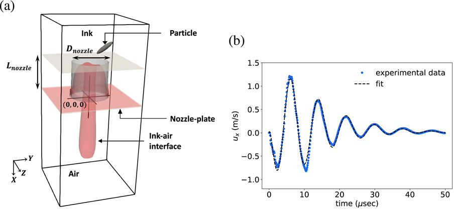
Figure 4. (a) Schematic of the numerical domain for simulating liquid jetting with a particle near or inside the nozzle. The 3D rendering shows the domain with the red surface representing the ink-air interface at a given time. The origin (0, 0, 0) is set at the nozzle exit center. (b) Inlet velocity profile used in simulations: initial negative velocity causes meniscus retraction, followed by positive velocity causing jetting and continued oscillations. A fitted function for the inlet velocity is provided by our collaborators at Canon Industrial Printing:
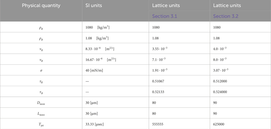
Table 2. Input parameters for liquid jetting simulations in the presence of solid particles (of different size and shape) as used in Sections 3.1, 3.2. Suffixes
The position and size of the ellipsoid have been manually extracted from the first
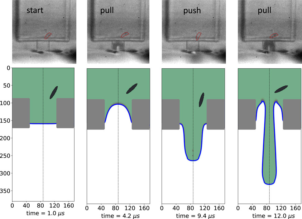
Figure 5. Cross-sectional view of liquid jetting with realistic ink-air parameters (see Table 2) and inflow pulse shown in Figure 4B, qualitatively compared with experiments. The spheroidal particle is initialized to match the first experimental frame, with position and orientation closely matching throughout. This confirms that the simulated flow and particle dynamics qualitatively reproduce experimental observations. Ink is shown in light green; the ink-air interface is marked by the blue curve.
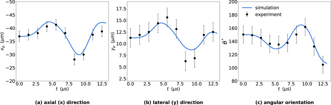
Figure 6. Comparison of particle dynamics from simulations and experiments. Vertical
We start by presenting the case shown in Figure 5, where the particle is initialized at
To further assess the robustness of our results, we performed a sensitivity analysis on the following uncertain parameters: (a) the initial position
and similarly, for the angular orientation
Here,
3.2 Liquid jetting with a solid particle: shape and size dependency
In a follow-up step, we investigate the influence of particle shape and size on the dynamics of solid inclusions inside a nozzle during liquid jetting. Specifically, our objective is to quantify both translational and angular motion in a pulse-driven jetting cycle, using the experimental velocity profile shown in Figure 4b.
The jetting parameters used in this study are summarized in Table 2, and the numerical domain used is the same as shown in Figure 4. The size of the domain is
We present here results for three representative cases. Two sets of simulations were performed with spherical particles, varying the radius of the sphere between 5 and 15 LU and initializing the particle inside the nozzle or in the feed-through, were performed. The results are shown in Figures 7A,B, respectively. Additionally, a set of simulations was conducted with spheroidal particles, with varying aspect ratios
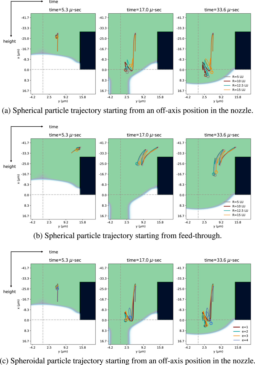
Figure 7. (a) Particle trajectories over time for different radii (
Figure 7 shows the trajectory of the CoM of the particles as a function of time, starting from two different initial positions. Within the explored parameter range, we observe that both spherical and spheroidal particles exhibit similar trajectories, also converging to comparable final positions. These results suggest that, at least for trajectory prediction purposes, spheroidal particles with modest aspect ratios can effectively be approximated by spheres.
Figure 8a shows the angular velocity profiles for spherical particles of different radii. Despite some variations, all follow a similar temporal trend. For spheroidal particles (cf. Figure 8b), we observe larger angular velocities compared to volume-equivalent spheres. However, angular velocity differences between spheroids of varying aspect ratios remain minimal, with noticeable discrepancies only near
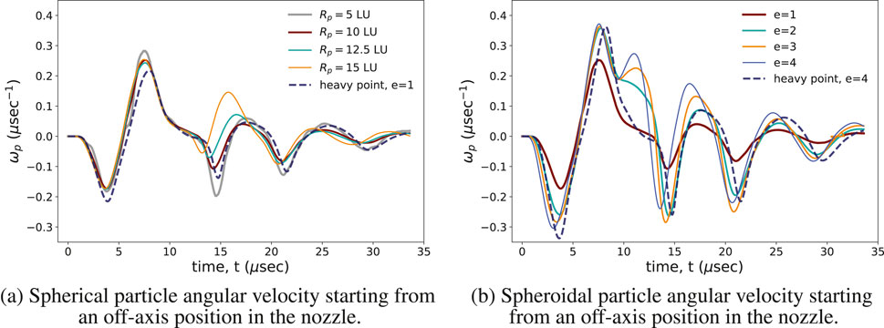
Figure 8. Particle angular velocity over time during a jetting cycle. (a) Spherical particles with radii
In conclusion, this analysis of translational and rotational dynamics suggests that within the industrially relevant parameter ranges explored, spherical particles represent a reasonable approximation for spheroidal particles.
3.3 Dynamics of solid inclusions with the heavy-point-particle model
In this section, we evaluate the dynamics of solid particles within the nozzle and feed-through during liquid jetting using the heavy-point-particle model introduced in Section 2.5. We compare this simplified model, fully resolved particle simulations, and tracer-based approaches, focusing on both translational and rotational dynamics. The numerical setup follows the configuration described in Section 3.2, with simulation parameters listed in Table 2. Figure 9 illustrates the spatial distribution of tracers and heavy point particles over time during the first two jetting cycles. Both types of particles, ejected during the first ejection cycle, are color-coded (blue for heavy particles and orange for tracers). Point particles are initialized inside the nozzle and part of the feed-through, areas prone to host impurities at the early stages of the jetting process. The reliability of the heavy-point-particle model depends on the fidelity of the fluid solver, particularly its spatial and temporal resolution. To ensure meaningful comparison with fully resolved particles while keeping computational costs manageable, we initialize about
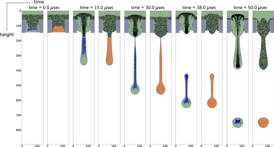
Figure 9. Time evolution of heavy particles (left) and tracers (right) during a jetting cycle. Particles ejected in the first cycle are highlighted in blue (heavy particles) and orange (tracers). Simulations use approximately 200,000 particles, with only those in the central symmetry plane shown. The heavy point particles follow Equation 16 with relaxation time
For the case shown in Figure 9 we have initialized a total of approximately
We first compare the dynamics of a heavy point particle with that of the fully resolved particle and also tracers starting from the same location inside the nozzle as shown in Figure 10. We observe that, across the particle sizes considered, the heavy-point-particle trajectories qualitatively match those of their fully resolved counterparts, whereas tracers, lacking inertia, simply follow the fluid streamlines and are ejected with the ink droplets.
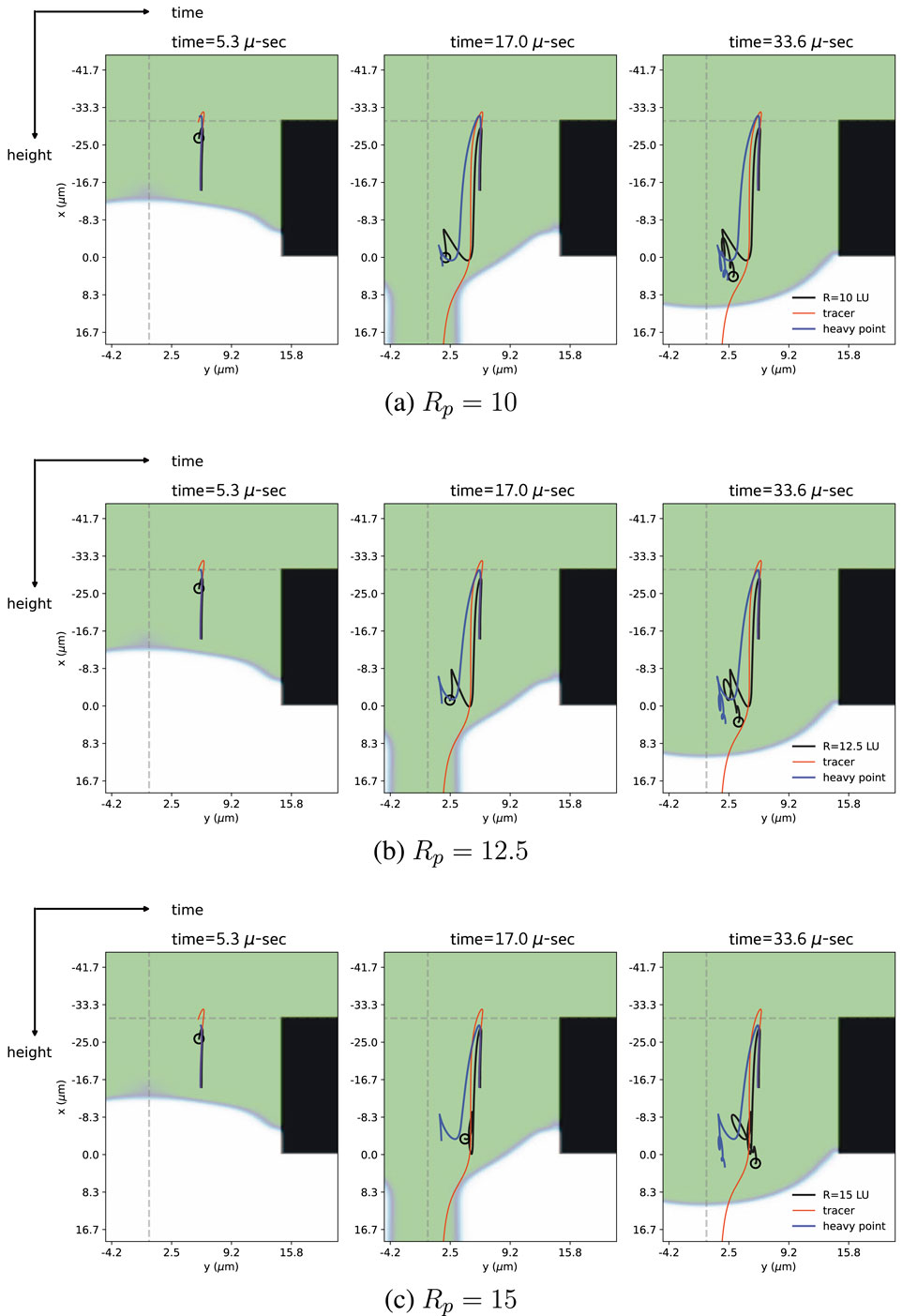
Figure 10. Particle trajectories during a jetting cycle for a fully-resolved spherical particle (black), a heavy point particle (blue), and a tracer (orange). All cases use matched Stokes numbers
We also compare the angular dynamics of the heavy point particles using the Jeffery equation. Figure 8 presents a comparison of angular velocity for two cases: (i) spherical particles of varying size, see Figure 8a, and (ii) spheroidal particles with different aspect ratios, see Figure 8b, all initialized from the same position within the nozzle. Despite the fact that the Jeffery model neglects inertial effects on angular motion, it reproduces the angular velocity profiles observed in fully resolved simulations with reasonable accuracy (blue dashed curves in Figure 8).
These findings suggest that the one-way coupled heavy-point-particle model can provide a computationally efficient yet sufficiently reliable approximation of particle dynamics, both translational and rotational, within the scope of industrially relevant conditions, making it an excellent choice when the primary focus is on the particle trajectories. Clearly, if the objective is instead to investigate the impact of the particles on the jetting process, including the resulting asymmetries, a fully two-way coupled model is required.
4 Conclusion
Solid inclusions are commonly present in jetting processes, either as part of the intended printed material or as debris that can compromise the quality of the jetting. The complex dynamics of such coupled fluid-particle systems poses significant challenges, both experimentally and numerically.
We used a multicomponent solver capable of describing the combined dynamics of air-ink interfaces as well as the fluid-structure interaction between ink and a solid inclusion. The numerical model implements a fully 3D two-way coupling and allows one to simulate, at realistic values of the physical parameters, the complex dynamics of a jetting process in the presence of solid inclusions inside the nozzle. We employed the LBM to solve the flow velocity field, and we coupled it to the CG method to simulate the evolution of the ink-air interface. The stability and physical fidelity of the method were enhanced by incorporating the CM scheme, thereby extending the accessible density parameter space. To simulate the fully resolved two-way coupled fluid-particle interaction, we adopted the MBB scheme, allowing the simulation of solid inclusions inside the nozzle. The focus in the present numerical investigation is primarily on the dynamics of the solid inclusions and not on asymmetric jetting due to the presence of these inclusions.
We conducted simulations involving both spherical and ellipsoidal particles of varying sizes and aspect ratios, within a range relevant to industrial applications. Our findings indicate that within this range, particles released from the same initial position exhibit similar trajectories and angular dynamics. Although particle size and shape can influence droplet formation during jetting, the fact that the trajectories of these particles remain similar suggests that the effects of size and shape on jetting are sufficiently minor. For future jetting studies, the dynamics of solid inclusions can reasonably be approximated by those of spheres.
The two-way coupled model has the ability to simulate particle dynamics and predict particle ejection over single and multiple jetting cycles, but its computational cost may be impractically high for industrial applications. To address this limitation, we have implemented a heavy-point-particle model that uses the Stokes equation to compute particle trajectories while also accounting for inertial effects. The angular velocity is determined using a modified Jeffery equation for a rotating ellipsoid in a uniform shear flow. We observed that the trajectory matches quite well with the results obtained from fully resolved simulations. Although the angular dynamics does not incorporate inertia, the angular velocity observed in our heavy-point-particle model also reasonably matches the angular velocities observed in fully resolved simulations. Since the heavy point particle model is one-way coupled, the dynamics of a huge number of particles (up to
In future work, we plan to extend the heavy-point-particle model to address some of its current limitations. For example, limiting the hydrodynamic forces on the solid inclusions to the Stokes drag force might be a too drastic simplification in some situations. Other forces in the MR equation, such as added mass or pressure gradient force, could contribute significantly. Additionally, the model assumes that particle sizes are much smaller than the velocity gradient length scale, a condition that may not hold in realistic scenarios. To overcome this, we could incorporate Faxén correction terms, which account for finite-size effects in non-uniform flows and would improve the reliability of the model in more complex shear environments near boundaries.
Moreover, surface tension effects are not accounted for in the current model, which means that interactions between particles and the ink-air interface are not captured. This limitation becomes particularly relevant when investigating the impact of particles on the jet and the resulting asymmetries. If the focus is on particle dynamics alone, the current simplified model offers a computational advantage. However, for studies involving the interaction of particles with the jet, including the resulting distortions and asymmetries, a fully two-way coupled model is necessary. Finally, we plan to investigate the asymmetries that arise in the resulting ink droplets due to the presence of both stationary and mobile solid inclusions within the nozzle and feedthrough during jetting.
Data availability statement
The original contributions presented in the study are included in the article/Supplementary Material, further inquiries can be directed to the corresponding author.
Author contributions
ArG: Data curation, Formal Analysis, Investigation, Software, Writing – original draft. AlG: Formal Analysis, Investigation, Software, Writing – original draft, Writing – review and editing. HW: Conceptualization, Supervision, Writing – review and editing. HC: Conceptualization, Formal Analysis, Investigation, Supervision, Writing – original draft, Writing – review and editing. FT: Conceptualization, Formal Analysis, Funding acquisition, Investigation, Supervision, Writing – original draft, Writing – review and editing.
Funding
The authors declare that financial support was received for the research and/or publication of this article. This publication is part of the project Fundamental of Inkjet Printing (FIP) (with project number FIP NWOI-18.0166) in collaboration with Canon Production Printing Netherlands B.V and the work is (partly) sponsored by NWO domain Science for the use of supercomputer facilities. A.G. gratefully acknowledges the support of the U.S. Department of Energy through the LANL/LDRD Program under project number 20240740PRD1 and the Center for Non-Linear Studies for this work.
Acknowledgements
Herman Wijshoff passed away on 10 May 2023. He was key to the conceptualisation of this work. He will be sadly missed.
Conflict of interest
Author HW was employed by Canon Production Printing Netherlands B.V.
The remaining authors declare that the research was conducted in the absence of any commercial or financial relationships that could be construed as a potential conflict of interest.
The author(s) declared that they were an editorial board member of Frontiers, at the time of submission. This had no impact on the peer review process and the final decision.
The authors declare that this study received funding from Canon Production Printing Netherlands B.V. The funder had the following involvement in the study: sharing knowledge and co-supervision of the research.
Generative AI statement
The authors declare that no Generative AI was used in the creation of this manuscript.
Any alternative text (alt text) provided alongside figures in this article has been generated by Frontiers with the support of artificial intelligence and reasonable efforts have been made to ensure accuracy, including review by the authors wherever possible. If you identify any issues, please contact us.
Publisher’s note
All claims expressed in this article are solely those of the authors and do not necessarily represent those of their affiliated organizations, or those of the publisher, the editors and the reviewers. Any product that may be evaluated in this article, or claim that may be made by its manufacturer, is not guaranteed or endorsed by the publisher.
Supplementary material
The Supplementary Material for this article can be found online at: https://www.frontiersin.org/articles/10.3389/fphy.2025.1702044/full#supplementary-material
References
1. Wijshoff H. The dynamics of the piezo inkjet printhead operation. Phys Rep (2010) 491:77–177. doi:10.1016/j.physrep.2010.03.003
2. Dilag J, Chen T, Li S, Bateman SA. Design and direct additive manufacturing of three-dimensional surface micro-structures using material jetting technologies. Additive Manufacturing (2019) 27:167–74. doi:10.1016/j.addma.2019.01.009
3. García-Alvarado R, Moroni-Orellana G, Banda-Pérez P. Architectural evaluation of 3d-printed buildings. Buildings (2021) 11:254. doi:10.3390/buildings11060254
4. Wang X, Jiang M, Zhou Z, Gou J, Hui D. 3d printing of polymer matrix composites: a review and prospective. Composites B: Eng (2017) 110:442–58. doi:10.1016/j.compositesb.2016.11.034
5. Eshkeiti A, Reddy ASG, Emamian S, Narakathu BB, Joyce M, Joyce M, et al. Screen printing of multilayered hybrid printed circuit boards on different substrates. IEEE Trans Components, Packaging Manufacturing Technology (2015) 5:415–21. doi:10.1109/TCPMT.2015.2391012
6. Cheng YB, Pascoe A, Huang F, Peng Y. Print flexible solar cells. Nature (2016) 539:488–9. doi:10.1038/539488a
7. Florian C, Piazza S, Diaspro A, Serra P, Duocastella M. Direct laser printing of tailored polymeric microlenses. ACS Appl Mater & Inter (2016) 8:17028–32. doi:10.1021/acsami.6b05385
9. Mannoor MS, Jiang Z, James T, Kong YL, Malatesta KA, Soboyejo WO, et al. 3d printed bionic ears. Nano Lett (2013) 13:2634–9. doi:10.1021/nl4007744
10. Dordlofva C. A design for qualification framework for the development of additive manufacturing Components—a case study from the space industry. Aerospace (2020) 7:25. doi:10.3390/aerospace7030025
12. Lohse D. Fundamental fluid dynamics challenges in inkjet printing. Annu Rev Fluid Mech (2022) 54:349–82. doi:10.1146/annurev-fluid-022321-114001
13. Hack MA, Vondeling P, Cornelissen M, Lohse D, Snoeijer JH, Diddens C, et al. Asymmetric coalescence of two droplets with different surface tensions is caused by capillary waves. Phys Rev Fluids (2021) 6:104002. doi:10.1103/PhysRevFluids.6.104002
14. Li Y, Diddens C, Prosperetti A, Chong KL, Zhang X, Lohse D. Bouncing oil droplet in a stratified liquid and its sudden death. Phys Rev Lett (2019) 122:154502. doi:10.1103/PhysRevLett.122.154502
15. Sanjay V, Lohse D, Jalaal M. Bursting bubble in a viscoplastic medium. J Fluid Mech (2021) 922:A2. doi:10.1017/jfm.2021.489
16. Berny A, Deike L, Séon T, Popinet S. Role of all jet drops in mass transfer from bursting bubbles. Phys Rev Fluids (2020) 5:033605. doi:10.1103/PhysRevFluids.5.033605
17. De Rosis A, Coreixas C. Multiphysics flow simulations using d3q19 lattice boltzmann methods based on central moments. Phys Fluids (2020) 32:117101. doi:10.1063/5.0026316
18. De Rosis A, Huang R, Coreixas C. Universal formulation of central-moments-based lattice boltzmann method with external forcing for the simulation of multiphysics phenomena. Phys Fluids (2019) 31:117102. doi:10.1063/1.5124719
19. Leclaire S, Parmigiani A, Malaspinas O, Chopard B, Latt J. Generalized three-dimensional lattice boltzmann color-gradient method for immiscible two-phase pore-scale imbibition and drainage in porous media. Phys Rev E (2017) 95:033306. doi:10.1103/PhysRevE.95.033306
20. Ladd AJ. Numerical simulations of particulate suspensions via a discretized boltzmann equation. Part 1. Theoretical foundation. J Fluid Mech (1994) 271:285–309. doi:10.1017/S0022112094001771
21. Ladd AJ. Numerical simulations of particulate suspensions via a discretized boltzmann equation. part 2. numerical results. J Fluid Mech (1994) 271:311–39. doi:10.1017/S0022112094001783
22. Aidun CK, Lu Y, Ding EJ. Direct analysis of particulate suspensions with inertia using the discrete boltzmann equation. J Fluid Mech (1998) 373:287–311. doi:10.1017/S0022112098002493
23. Elghobashi S. On predicting particle-laden turbulent flows. Appl Scientific Res (1994) 52:309–29. doi:10.1007/BF00936835
24. Crowe CT, Sommerfeld M, Tsuji Y. Multiphase flows with droplets and particles. New York: Taylor & Francis Group (1998). doi:10.1201/b11103
25. Balachandar S, Eaton JK. Turbulent dispersed multiphase flow. Annu Rev Fluid Mech (2010) 42:111–33. doi:10.1146/annurev.fluid.010908.165243
26. Maxey MR, Riley JJ. Equation of motion for a small rigid sphere in a nonuniform flow. The Phys Fluids (1983) 26:883–9. doi:10.1063/1.864230
27. Batchelor GK. An introduction to fluid dynamics. In: Cambridge mathematical library. Cambridge University Press (2000). doi:10.1017/CBO9780511800955
28. Succi S. The lattice boltzmann equation: for complex states of flowing matter OUP Oxford. Oxford university press (2018). doi:10.1093/oso/9780199592357.001.0001
29. Krüger T, Kusumaatmaja H, Kuzmin A, Shardt O, Silva G, Viggen EM. The lattice boltzmann method - principles and practice. Springer (2016). doi:10.1007/978-3-319-44649-3
30. Wolf-Gladrow DA. Lattice-gas cellular automata and lattice boltzmann models: an introduction. Springer (2004). doi:10.1007/b72010
31. Datadien K, Di Staso G, Toschi F. Numerical stability analysis for a stationary and translating droplet at extremely low viscosity values using the lattice boltzmann method color-gradient multi-component model with central moments formulation. Commun Comput Phys (2023) 33:330–48. doi:10.4208/cicp.OA-2022-0053
32. Leclaire S, Pellerin N, Reggio M, Trépanier JY. Enhanced equilibrium distribution functions for simulating immiscible multiphase flows with variable density ratios in a class of lattice boltzmann models. Int J Multiphase Flow (2013) 57:159–68. doi:10.1016/j.ijmultiphaseflow.2013.07.001
33. Gunstensen AK, Rothman DH, Zaleski S, Zanetti G. Lattice boltzmann model of immiscible fluids. Phys Rev A (1991) 43:4320–7. doi:10.1103/PhysRevA.43.4320
34. Bhatnagar P, Gross E, Krook M. A model for collision processes in gases. I. small amplitude processes in charged and neutral one-component systems. Phys Rev (1954) 94:511–25. doi:10.1103/PhysRev.94.511
35. Saito S, De Rosis A, Festuccia A, Kaneko A, Abe Y, Koyama K. Color-gradient lattice boltzmann model with nonorthogonal central moments: hydrodynamic melt-jet breakup simulations. Phys Rev E (2018) 98:013305. doi:10.1103/PhysRevE.98.013305
36. Datadien KP, Di Staso G, Wijshoff H, Toschi F. A quantitative comparison of physical accuracy and numerical stability of lattice boltzmann color gradient and pseudopotential multicomponent models for microfluidic applications. Commun. Comput. Phys. (2021) 32 (2):450–489. doi:10.4208/cicp.OA-2021-0204
37. Montessori A, Lauricella M, Tirelli N, Succi S. Mesoscale modelling of near-contact interactions for complex flowing interfaces. J Fluid Mech (2019) 872:327–47. doi:10.1017/jfm.2019.372
38. Monteferrante M, Montessori A, Succi S, Pisignano D, Lauricella M. Lattice boltzmann multicomponent model for direct-writing printing. Phys Fluids (2021) 33:042103. doi:10.1063/5.0046555
39. Datadien K. Directional instabilities in microdroplet jetting: a numerical approach. Netherlands: Eindhoven University of Tecnhnology (2024).
40. Datadien K, Di Staso G, Diddens C, Wijshoff H, Toschi F. Comparison of lattice boltzmann, finite element and volume of fluid multicomponent methods for microfluidic flow problems and the jetting of microdroplets. Commun Comput Phys (2023) 33:912–36. doi:10.4208/cicp.OA-2022-0181
41. De Rosis A. Nonorthogonal central-moments-based lattice boltzmann scheme in three dimensions. Phys Rev E (2017) 95:013310. doi:10.1103/PhysRevE.95.013310
43. Ghosh A, Gabbana A, Wijshoff H, Toschi F. Effective force stabilising technique for the immersed boundary method. Commun Comput Phys (2023) 33:349–66. doi:10.4208/cicp.OA-2022-0058
44. van Aartrijk M, Clercx HJH. Vertical dispersion of light inertial particles in stably stratified turbulence: the influence of the basset force. Phys Fluids (2010) 22:013301. doi:10.1063/1.3291678
45. Mograbi E, Bar-Ziv E. On the asymptotic solution of the maxey-riley equation. Phys Fluids (2006) 18:051704. doi:10.1063/1.2204064
46. Talaei A, Garrett TJ. On the maxey-riley equation of motion and its extension to high reynolds numbers (2020) doi:10.48550/arXiv.2006.16577
47. Vera ASG. Sediment transport and morphodynamics induced by vortices. Netherlands: Eindhoven University of Tecnhnology (2020).
48. Calzavarini E, Volk R, Lévêque E, Pinton JF, Toschi F. Impact of trailing wake drag on the statistical properties and dynamics of finite-sized particle in turbulence. Physica D: Nonlinear Phenomena (2012) 241:237–44. doi:10.1016/j.physd.2011.06.004
49. Armenio V, Fiorotto V. The importance of the forces acting on particles in turbulent flows. Phys Fluids (2001) 13:2437–40. doi:10.1063/1.1385390
50. van Hinsberg MAT, Clercx HJH, Toschi F. Enhanced settling of nonheavy inertial particles in homogeneous isotropic turbulence: the role of the pressure gradient and the basset history force. Phys Rev E (2017) 95:023106. doi:10.1103/PhysRevE.95.023106
51. Hjelmfelt A, Mockros L. Motion of discrete particles in a turbulent fluid. Appl Scientific Res (1966) 16:149–61. doi:10.1007/BF00384062
52. Jeffery GB, Filon LNG. The motion of ellipsoidal particles immersed in a viscous fluid. Proc R Soc Lond Ser A, Containing Pap a Math Phys Character (1922) 102:161–79. doi:10.1098/rspa.1922.0078
53. Fraters A, van den Berg M, de Loore Y, Reinten H, Wijshoff H, Lohse D, et al. Inkjet nozzle failure by heterogeneous nucleation: bubble entrainment, cavitation, and diffusive growth. Phys Rev Appl (2019) 12:064019. doi:10.1103/PhysRevApplied.12.064019
Keywords: inkjet printing, computational fluid dynamics, lattice Boltzmann method, multi-phase flow, point-particle modeling
Citation: Ghosh A, Gabbana A, Wijshoff H, Clercx HJH and Toschi F (2025) Numerical simulations of liquid jetting with solid inclusions. Front. Phys. 13:1702044. doi: 10.3389/fphy.2025.1702044
Received: 09 September 2025; Accepted: 07 November 2025;
Published: 04 December 2025.
Edited by:
Minping Wan, Southern University of Science and Technology, ChinaReviewed by:
Yumei Yong, Chinese Academy of Sciences (CAS), ChinaXiang Li, Southern University of Science and Technology, China
Copyright © 2025 Ghosh, Gabbana, Wijshoff , Clercx and Toschi. This is an open-access article distributed under the terms of the Creative Commons Attribution License (CC BY). The use, distribution or reproduction in other forums is permitted, provided the original author(s) and the copyright owner(s) are credited and that the original publication in this journal is cited, in accordance with accepted academic practice. No use, distribution or reproduction is permitted which does not comply with these terms.
*Correspondence: Federico Toschi, Zi50b3NjaGlAdHVlLm5s