 Rashid Nasimov1,2
 Michal Prauzek3Jaromir Konecny3Maha Abdelhaq4Roosvel Soto-Diaz5*José Escorcia-Gutierrez6Darius Andriukaitis7*
- 1Department of Computer Engineering, Gachon University, Seongnam-si, Republic of Korea
- 2Department of Artificial intelligence, Tashkent State University of Economics, Tashkent, Uzbekistan
- 3Department of Cybernetics and Biomedical Engineering, VSB - Technical University of Ostrava, Ostrava-Poruba, Czechia
- 4Department of Information Technology, College of Computer and Information Sciences, Princess Nourah Bint Abdulrahman University, Riyadh, Saudi Arabia
- 5Biomedical Engineering Program, Universidad Simón Bolívar, Barranquilla, Colombia
- 6Department of Computational Science and Electronics, Universidad de la Costa, CUC, Barranquilla, Colombia
- 7Department of Electronics Engineering, Faculty of Electrical and Electronics Engineering, Kaunas University of Technology, Kaunas, Lithuania
Introduction: Because it is anticipated to be a new physical quantity for communication multiplexing and has significant potential for increasing channel capacity and enhancing spectrum resource utilization, researchers have been looking more closely at orbital angular momentum (OAM). Because of its potential to increase transmission capacity, vortex beams carrying orbital angular momentum (OAM) have recently become a focus of much investigation. One of the main challenges now is how to effectively manufacture OAM in the terahertz (THz) spectrum because existing THz vortex wave generation devices are constrained by only functioning at one frequency, having a small bandwidth, and having low conversion efficiency.
Methods: Therefore, this paper proposes a novel OAM metasurface design for generating vortex electromagnetic waves in the THz spectrum. The Pancharatnam-Berry phase idea and the phase superposition principle were used to create a single-layer reflective metasurface and a projected ultra-wideband reflective meta-atom.
Results and discussion: Each OAM mode in the reflected field was broken down using the Fourier transform, and the purity of the OAM modes was quantitatively examined. The dominant OAM mode had the highest energy weight share (l = −2) in all vortex waves at various frequencies, and the designed metasurface was further optimized to enhance the energy share corresponding to the dominant mode. With its high main mode energy, wide operating bandwidth, and excellent conversion efficiency, the proposed metasurface provides a benchmark for the effective production of wideband THz vortex waves.
1 Introduction
Electrical waves with wavelengths between microwaves and infrared, ranging from 0.03 mm to 3 mm, and frequency between 0.3 THz and 10 THz are known as terahertz (THz) waves. Compared with microwaves, THz waves have narrower beams and have advantages such as large communication bandwidth, strong anti-interference ability, high resolution, and low photon energy. They also have the penetrability of millimeter waves and the controllability of light waves. It has a lot of potential applications in the domains of high-speed communications [1–3], bioimaging [4–6], holographic projection [7–9], and spectral detection [10–12]. Electromagnetic waves carry both linear and angular momentum; examples of angular momentum are orbital angular momentum (OAM) and spin angular momentum (SAM) [13, 14]. OAM, as a basic physical quantity of electromagnetic waves, was discovered and defined in Laguerre–Gaussian (LG) beams by [15] and has attracted widespread attention from researchers at home and abroad.
An essential aspect of electromagnetic waves is that their amplitude and polarization characteristics are the same as the OAM. They are all physical properties of electromagnetic waves. The beam carrying OAM is also called a vortex beam, and its phase distribution is
Metasurfaces are thin-film devices composed of subwavelength structures that can obtain phase mutations on a two-dimensional plane at a subwavelength scale. They have low profiles, strong controllability, low losses, and are easy to process. These advantages make them one of the ideal methods for generating THz-OAM beams. Compared with natural materials, it has high flexibility and provides a new idea and method for the development of efficient wavefront control in the terahertz band. As of right now, scientists have finished a number of studies on THz wavefront control based on metasurfaces and investigated its many potential uses in vector beams, multiplexing, lenses, holography, etc. Considering the characteristics of different materials, periods and electromagnetic field distribution, the work of terahertz metasurface wavefront control can be divided into metal and dielectric metasurfaces, periodic, quasi-periodic and randomly distributed metasurfaces, and metasurface far-field and near-field wavefront control. These include the far-field and near-field wavefront control of THz, which differ greatly in concept, implementation technique, and application scenario due to the electromagnetic field dispersion characteristics. First, far-field wavefront control is the control of spatial light, and near-field control is mainly for bound states propagating on the surface, including surface waves or boundary states. There is an essential difference in the dispersion curves of the two. Secondly, the two also have great differences in processing methods and generation and detection means; in addition, there are also great differences in the application scenarios of far-field and near-field metasurface wavefront control. THz metasurfaces provide efficient solutions, such as high-resolution imaging and quick detection, because of their unique electromagnetic characteristics and microscale periodic structures. The drawbacks of conventional OAM sources in OAM production can be addressed by metasurfaces. It boosts the OAM generator performance by modifying electromagnetic waves, particularly in communication enhancement through increased bandwidth and conversion efficiency.
With a spiral spatial phase distribution
Traditional methods of generating vortex waves include annular array antennas [19], spiral phase plates [20] and holographic diffraction gratings. Among them, the annular array antenna requires the design of a complex feeding network, which has high system costs. Other optical devices are large in size and expensive, which is not conducive to integration and miniaturization. In order to circumvent intricate feeding designs, metasurfaces [21, 22] are a revolutionary artificial structure made up of subwavelength components that can dynamically regulate electromagnetic waves’ polarization, phase, and amplitude. Because of their compact size, light weight, low production cost, and ease of processing, researchers choose them. Terahertz vortex beams are now best produced using metasurfaces. In recent years, more and more researchers have tried to generate vortex waves through metasurfaces. For example, the authors in [23] proposed a metasurface with a “V” unit structure, which achieved the vortex wave generation with
This paper proposes a broadband THz vortex wave metasurface composed of a single-layer geometric phase unit. The main innovations of this article are as follows.
1. The geometric phase is also called pancharatnam-berry (P-B) phase. The P-B phase is independent of frequency and is only related to the phase control related to the unit rotation angle, which realizes the high-efficiency generation of THz vortex waves.
2. By rotating the metasurface unit to obtain a reflection phase range of 0°–360°, a metasurface with
3. The simulation results under circularly polarized plane wave excitation show that the ultra-broadband terahertz vortex wave metasurface proposed in this paper has the following advantages: a) Vortex waves are generated in a range of 0.82 THz to 2.09 THz (relative bandwidth 87.3%); b) The conversion efficiency of the metasurface is higher than 94.7%; c) The OAM mode purity is high, which provides a reference for efficient generation of THz vortex waves.
The remainder of this paper is organized as follows. In Section 2, the theoretical analysis and metasurface unit design is presented. In Section 3, the broadband vortex wave metasurface design is discussed. In Section 4, the simulations analysis is performed followed by performance comparison. In Section 5, the conclusion is discussed.
2 Theoretical analysis and metasurface unit design
The principle of the reflective metasurface to generate vortex beams is to reflect the plane wave with SAM into a structural wave carrying OAM. In order to simplify the design process and design high-performance units more conveniently, this study examines the metasurface’s incident field and dispersed field using the Jones matrix. The conversion process of SAM-OAM under the incidence of circularly polarized waves is as follows, as seen in Figure 1, in the rectangular coordinate system, following the rotation of the metasurface unit by an angle
where,
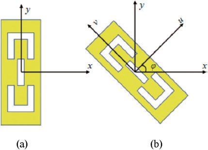
Figure 1. Metasruface unit design. (a) No rotation; (b) With rotation.
According to the P-B phase theory, any phase difference of 0°–360° can be obtained by rotating the metasurface unit, and the spiral phase wavefront can be modulated into a reflected wave, which is a necessary condition for the metasurface to generate a vortex beam [28]. The designed metasurface compensation phase surface is constructed using units with different rotation angles, which can realize any expected wavefront control of the reflected electromagnetic wave. Under circularly polarized wave incidence, in order to achieve a higher SAM-OAM conversion efficiency, the amplitude of the reflection coefficients
In order to achieve a larger system operating bandwidth and efficiently generate vortex beams in a wide bandwidth, Equation 7 states that the phase of the metasurface unit’s co-polarization reflection coefficient at various rotation angles must have a similar slope within the (
Among them,
Based on the above discussion, in order to achieve high-performance SAM-OAM conversion, Figure 2a illustrates the anisotropic metasurface unit designed in this paper. Figure 2b illustrates the unit’s three-layer structure. The upper layer is a rectangular metal with a central opening and a “concave” groove that is symmetrical up and down. Polytetrafluoroethylene serves as the dielectric substrate in the middle layer. (F4B,
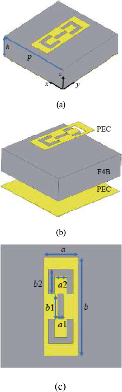
Figure 2. Anisotropic mestasurface unit design. (a) 3D side view; (b) Three-layer structure; (c) Unit structure.
3 Broadband vortex wave metasurface design
Considering that 1.5 THz is the center frequency and it is composed of
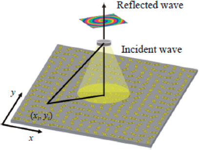
Figure 3. Vortex wave production principle by the metasurface.
The metasurface is set on the x-o-y plane which is illustrated in Figure 3, and the position of any unit in the metasurface can be expressed by coordinates
where,
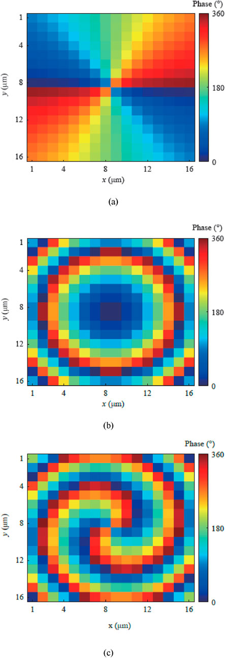
Figure 4. Phase distribution determination of metasurface. (a) Vortex phase
Where:
According to the compensation phase, the rotation angle of the unit at any position can be obtained as
4 Simulation results
4.1 Unit simulation results and analysis
We have given the structure and parameters of the metasurface unit above [43–45]. The simulation settings and simulation results of the metasurface unit are illustrated in Figure 5a. We can see from Figure 5b, the amplitude of the reflection spectrum is close to 1 under the incidence of x- and y-polarized waves, satisfying Equation 5. It has a phase difference of 180° in a wide band, satisfying Equation 6. These two points are necessary conditions for generating vortex waves in a wide band [46–48]. Equation 11 can be used to determine the unit’s conversion efficiency under the incidence of circularly polarized waves:
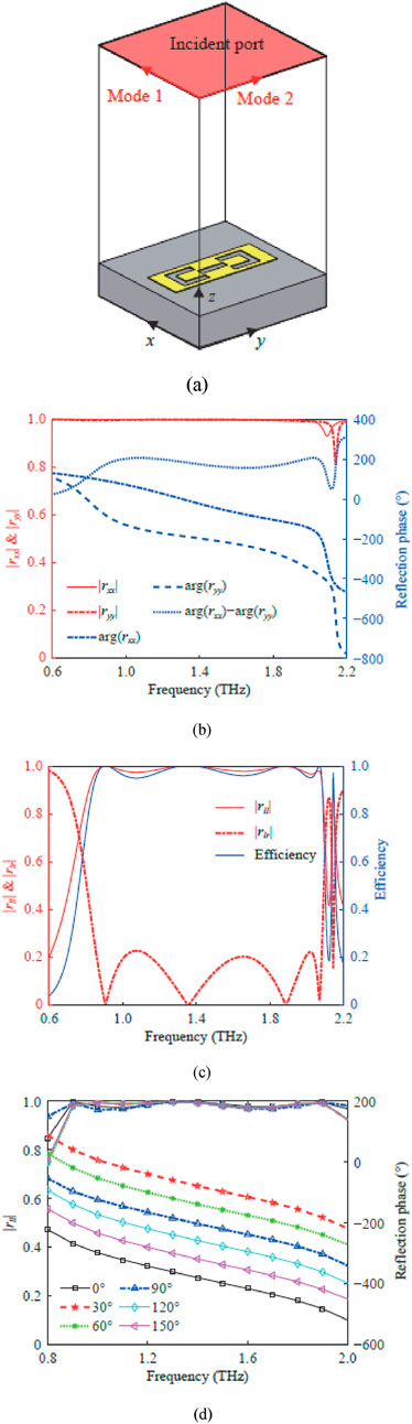
Figure 5. Simulation design and results. (a) Metasurface unit simulation setup; (b) Reflection spectrum and phase difference under linear polarization wave excitation; (c) Reflection spectrum and conversion efficiency under circularly polarized wave excitation; (d) Reflection spectra at different rotation angles under circular polarization wave excitation.
As shown in Figure 5c, under circular polarization wave incidence, in 0.82 THz ∼2.09 THz, the co-polarization reflection coefficient amplitude of the developed broadband unit is greater than 0.97 (relative bandwidth of 87.3%), a conversion efficiency greater than 94.7%, and a cross-polarization reflection coefficient amplitude less than 0.23 [49–51]. More importantly, it can be observed from Figure 5d that for the metasurface units at different rotation angles, the phase of their reflection spectra remains parallel within the bandwidth frequency range as expected, satisfying Equation 7, and the amplitude of the co-polarization reflection spectrum is greater than 0.95. These two points are very important for constructing a metasurface with high performance and high purity OAM characteristics.
The electromagnetic response simulation results of the metasurface unit above show that the metasurface unit proposed in this paper has high performance and can be used to construct an efficient broadband vortex wave metasurface [52–54].
4.2 Metasurface simulation results and discussion
According to the previously examined SAM-OAM conversion idea, the aforementioned metasurface units can be positioned at different rotational angles to construct a metasurface with the required vortex phase distribution
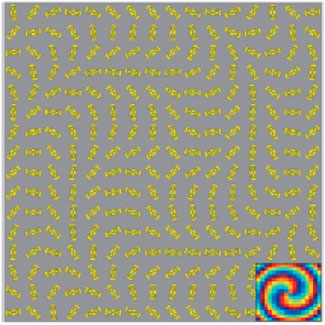
Figure 6. Metasurface topology with
The specific topology is composed of 16 × 16 rotated metasurface unit arrays. The numerical simulation uses 1 THz to 2 THz to demonstrate that the suggested metasurface may produce vortex waves in a wideband, and its vortex characteristics are verified by near- and far-field performance. Under RCP wave, the metasurface proposed in this paper generates a THz wave with
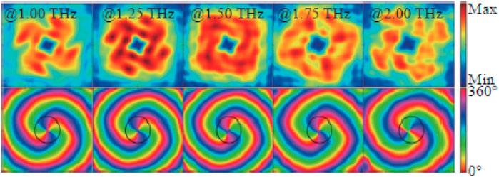
Figure 7. Amplitude and phase evaluation of vortex waves at
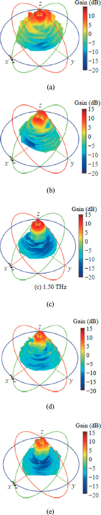
Figure 8. 3D radiation pattern evaluation of vortex waves at
The OAM mode purity can be used to describe the energy distribution of vortex waves with different mode numbers in the reflection field, which can well illustrate the quality of vortex waves [64–66]. This work decomposes several OAM modes in the reflection field using the Fourier transform in order to quantitatively examine the OAM mode purity. Using the phase singularity of the vortex beam as the center, the Fourier transform is applied to a circular electric field data set along the main beam. The corresponding calculation formula is as follows in Equations 12, 13:
Among them,
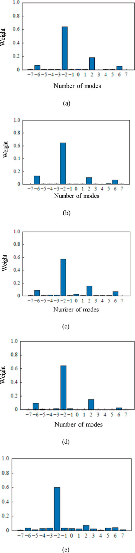
Figure 9. Spectral weight of OAM under different frequencies. (a) 1 THz; (b) 1.25 THz; (c) 1.50 THz; (d) 1.75 THz; (e) 2 THz.
4.3 Metasurface optimization simulation and discussion
In the above, we simulated the metasurface composed of 16 × 16 units and analyzed the mode intensity ratio. As shown in Figure 9, the intensity ratio of the main mode
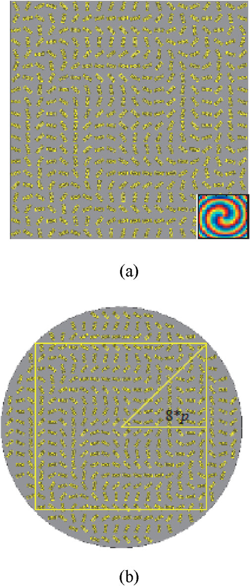
Figure 10. Optimized topology of metasurface with
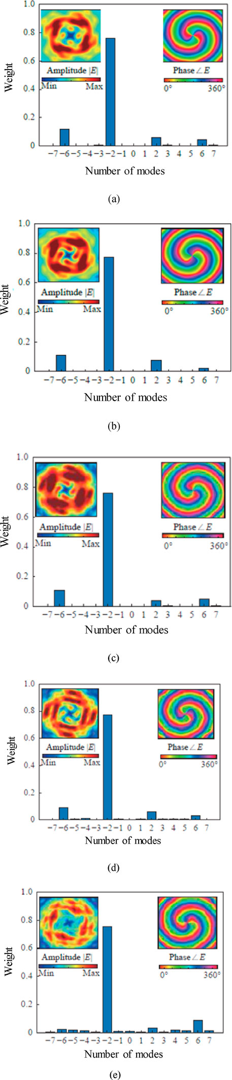
Figure 11. Energy proportion and spectral analysis of the rectangular metasurface in near-field. (a) 1 THz; (b) 1.25 THz; (c) 1.50 THz; (d) 1.75 THz; (e) 2 THz.
As shown in Figure 11, the energy proportion of the main mode
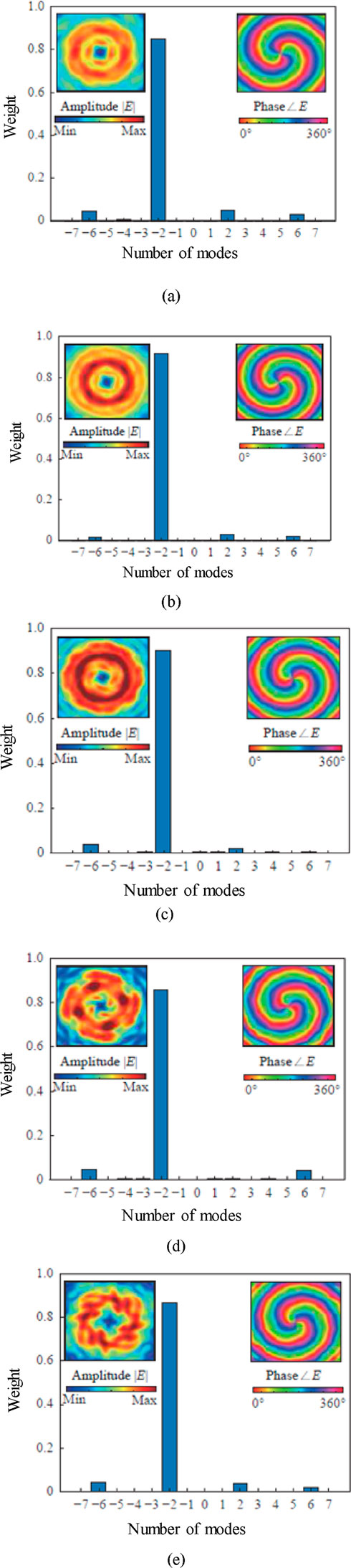
Figure 12. Energy proportion and spectral analysis of the circular metasurface in near-field. (a) 1 THz; (b) 1.25 THz; (c) 1.50 THz; (d) 1.75 THz; (e) 2 THz.
The significance of simulation calculation is to provide reference for practice. In actual processing, errors are inevitable in metasurfaces. Therefore, this paper takes possible errors into consideration in simulation to study their influence on the mode field distribution of reflected vortex waves. The size error is randomly selected as ±2 μm, and the rotation angle error distribution is shown in Figure 13a. A circular metasurface is constructed and simulated at the center frequency, as illustrated in Figure 13b. Under the influence of the error, the main mode intensity is significantly reduced, and the intensity of other crosstalk modes is increased. However, on the whole, within a certain range, the primary mode intensity still makes up the majority of the mode field distribution of the reflected vortex wave, and the error has minimal impact on it.
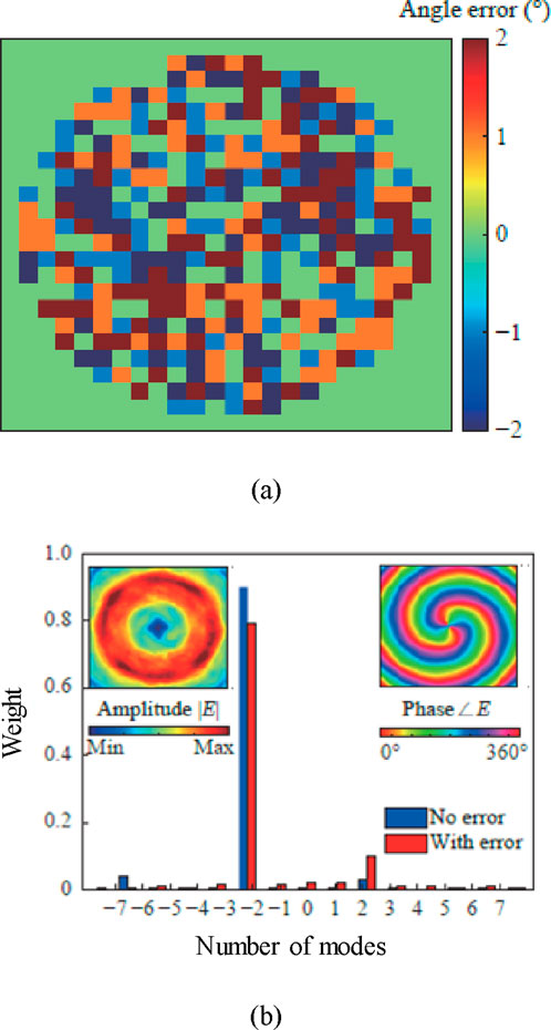
Figure 13. Vortex wave rotation angle error evaluation and spectral analysis. (a) Rotation angle error distribution; (b) Metasurface simulation results with errors (at 1.5 THz).
Figure 14 evaluates the efficiency of the metasurface for different operating frequencies. As can be seen from Figure 14, the performance under different OAM modes is consistent with desired performance which validates the effectiveness.
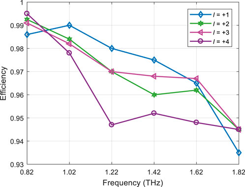
Figure 14. Efficiency evaluation of the metasurface.
Figure 15 evaluates the transmission coefficient of the metasurface with different values of THz frequencies. The x and y values of the transmission coefficient are analyzed. As can be seen from Figure 15, the transmission coefficient of both reached to maximum at 0.94 THz and 1.54 THz which is desired for practical deployment.
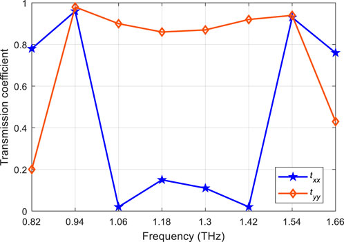
Figure 15. Transmission coefficient evaluation of the metasurface under various THz frequencies.
Table 1 shows the performance comparison of the unit designed by us and other units that generate OAM vortex wave beams in the THz band. The data used in Table 1 are all simulation data published in the corresponding articles. The results show that the unit designed by us can achieve efficient operation in a larger bandwidth and achieve a good balance between bandwidth and efficiency.

Table 1. Performance comparison of proposed and existing metasurface structures.
5 Conclusion
In this research, a high-performance geometric phase unit with free phase control of electromagnetic waves is proposed. To develop a broadband terahertz vortex wave metasurface with
Data availability statement
The original contributions presented in the study are included in the article/supplementary material, further inquiries can be directed to the corresponding authors.
Author contributions
RN: Writing – original draft, Writing – review and editing. MP: Conceptualization, Data curation, Formal Analysis, Funding acquisition, Investigation, Methodology, Project administration, Resources, Software, Supervision, Validation, Visualization, Writing – original draft, Writing – review and editing. JK: Conceptualization, Data curation, Formal Analysis, Funding acquisition, Investigation, Methodology, Resources, Software, Supervision, Validation, Writing – original draft, Writing – review and editing. MA: Conceptualization, Data curation, Formal Analysis, Investigation, Methodology, Resources, Supervision, Validation, Visualization, Writing – original draft, Writing – review and editing. RS-D: Conceptualization, Data curation, Formal Analysis, Investigation, Methodology, Resources, Supervision, Validation, Writing – original draft, Writing – review and editing. JE-G: Conceptualization, Data curation, Formal Analysis, Investigation, Methodology, Project administration, Validation, Visualization, Writing – original draft, Writing – review and editing. DA: Conceptualization, Data curation, Formal Analysis, Investigation, Methodology, Project administration, Resources, Software, Validation, Writing – original draft, Writing – review and editing.
Funding
The author(s) declare that financial support was received for the research and/or publication of this article. This research was supported by Princess Nourah bint Abdulrahman University Researchers Supporting Project Number (PNURSP2025R97), Princess Nourah bint Abdulrahman University, Riyadh, Saudi Arabia. This article has been produced with the financial support of the European Union under the REFRESH – Research Excellence For REgion Sustainability and High-tech Industries project number CZ.10.03.01/00/22_003/0000048 via the Operational Programme Just Transition.
Conflict of interest
The authors declare that the research was conducted in the absence of any commercial or financial relationships that could be construed as a potential conflict of interest.
Generative AI statement
The author(s) declare that no Generative AI was used in the creation of this manuscript.
Any alternative text (alt text) provided alongside figures in this article has been generated by Frontiers with the support of artificial intelligence and reasonable efforts have been made to ensure accuracy, including review by the authors wherever possible. If you identify any issues, please contact us.
Publisher’s note
All claims expressed in this article are solely those of the authors and do not necessarily represent those of their affiliated organizations, or those of the publisher, the editors and the reviewers. Any product that may be evaluated in this article, or claim that may be made by its manufacturer, is not guaranteed or endorsed by the publisher.
References
1. Tian H, Shen H, Zhang X, Li X, Jiang WX, Cui TJ. Terahertz metasurfaces: toward multifunctional and programmable wave manipulation. Front Phys (2020) 8:584077. doi:10.3389/fphy.2020.584077
2. Hu D, He S, Li S, Zhu W. A dynamic beam switching metasurface based on angular mode-hipping effect. Front Phys (2024) 12:1–13. doi:10.3389/fphy.2024.1392115
3. Hou J, Zhang X, Guo Y, Zhang R, Guo M. Design of electromagnetic metasurface using two dimensional crystal nets. Scientific Rep (2023) 13(7248):7248. doi:10.1038/s41598-023-32660-y
4. Hoang T, Fusco V, Abbasi M, Yurduseven O. Single-pixel polarimetric direction of arrival estimation using programmable coding metasurface aperture. Scientific Rep (2021) 11:23830. doi:10.1038/s41598-021-03228-5
5. Qian C, Kaminer I, Chen H. A guidance to intelligent metamaterials and metamaterials intelligence. Nat Commun (2025) 16:1154. doi:10.1038/s41467-025-56122-3
6. Yildirim H, Storrer L, Doncker P, Louveaux J, Horlin F. A multi-antenna super-resolution passive Wi-Fi radar algorithm: combined model order selection and parameter estimatoin. IET Radar, Sonar and Navigation (2022) 16(8):1376–1387. doi:10.1049/rsn2.12267
7. Venneri F, Costanzo S, Borgia A. Fractal metasurfaces and antennas: an overview of advanced applications in wireless communications. Appl Sci (2024) 14(7):1–17. doi:10.3390/app14072843
8. Cai H, Gu L, Hu H, Zhan Q. Enhancement methods for chiral optical signals by tailoring optical fields and nanostructures. Engineering (2025) 45:25–43. doi:10.1016/j.eng.2024.12.022
9. Liu Z, Xu Y, Ji C. Fano-enhanced circular dichoism in deformable stereo metasurfaces. Adv Mater (2020) 32(8):1–14. doi:10.1002/adma.201907077
10. Zanotto L, Balisteri G, Rovere A, Kwon O, Morandotti R, Piccoli R. Terahertz scanless hypertemportal imaging. Laser Photon Rev (2023) 17(8):1–14. doi:10.1002/lpor.202200936
11. Wan M, Healy J, Sheridan J. Terahertz phase imaging and biomedical applications. Opt and Laser Tech (2020) 122:105859. doi:10.1016/j.optlastec.2019.105859
12. Wan Z, Gao Z, Gao F, Renzo MD, Alouini MS. Terahertz massive MIMO with holographic reconfigurable intelligent surfaces. IEEE Trans Commun (2021) 69(7):4732–4750. doi:10.1109/tcomm.2021.3064949
13. Lan F, Wang L, Zeng H, Liang S, Song T, Liu W, et al. Real-time programmable metasurface for terahertz multifunctional wave front engineering. Light: Sci and Appl (2023) 12(191):191. doi:10.1038/s41377-023-01228-w
14. Liu Y, Xu Y, Yu B, Liu W, Zhang Z, Cheng H, et al. Terahertz metasurfaces for polarization manipulation and detection: principles and emerging applications. Adv Phys Res (2025) 4(2):2400100. doi:10.1002/apxr.202400100
15. Wang Y, Bai L, Huang C, Xie J, Zhang D, Guo L. Orbital angular momentum of laguerre-gaussian beams with Non-zero radial index at limited aperture size. Results Phys (2023) 48(1):106436. doi:10.1016/j.rinp.2023.106436
16. Zhou M, Zhang W, Sun J, Chu F, Dong G, Nie M, et al. Atomic fabrication of 2D materials using electron beams inside an electron microscope. Nanomaterials (2024) 14(21):1718. doi:10.3390/nano14211718
17. Yang T, Shi H, Guo J, Qiao Z. Orbital-angular momentum-based super-resolution ISAR imaging for maneuvering targets: modeling and performance analysis. Digital Signal Process. (2021) 117:103197. doi:10.1016/j.dsp.2021.103197
18. Gong L, Zhang Q, Zhang H. Optical orbital angular momentum multiplexed data transmission under high scattering. Light: Sci and Appl (2019) 8(1):1–13. doi:10.1038/s41377-019-0140-3
19. Wu J, Huang Z, Ren X. Wideband millimeter-wave dual-mode dual circularly polarized OAM antenna using sequentially rotating feeding technique. IEEE Antennas Wireless Propagation Lett (2020) 19(8):1296–1300. doi:10.1109/LAWP.2020.2997057
20. Naseri H, Pourmohammadi P, Melouki N, Ahmed F, Iqbal A, Denidni T. Frequency-adjustable OAM antenna with co-divergent beams for IoT applications. AEU – Int J Electron Commun (2024) 177:155188. doi:10.1016/j.aeue.2024.155188
21. Wang C, Yang Y, Yang W, Wu J, Huang X, Jin J, et al. Wideband dual-mode vortex wave metasurface based on distance inversion method. IEEE Trans Antennas Propagation (2024) 72(12):9401–9410. doi:10.1109/tap.2024.3470229
22. Ye L, Su W, Hu K, Ding Z, Hu Z, Ren R, et al. Multi-functional switchable terahertz metasurface device prediction by K-nearest neighbor. Chin J Phys (2024) 91(1):734–742. doi:10.1016/j.cjph.2024.07.016
23. Schake M. Examining and explaining the generalized laws of reflection and refraction at metasurface gratings. J Opt Soc America A (2022) 39(8):1352–1359. doi:10.1364/josaa.460037
24. Ren Q, Wang L, Wang T, Wang S, Zhou Y, Kang L, et al. Terahertz vortex beam generation based on reflective and transmissive graphene metasurfaces. Results Phys (2024) 62:107846. doi:10.1016/j.rinp.2024.107846
25. Esfandiari M, Lalbakhsh A, Shehni P, Jarchi S. Recent and emerging applications of graphene-based metamaterials in electromagnetics. Mater and Des (2022) 221:1–13. doi:10.1016/j.matdes.2022.110920
26. Yang Q, Wang Y, Liang L, Yang M. Broadband transparent terahertz vortex beam generator based on thermally tunable geometric metasurface. Opt Mater (2021) 121:111574. doi:10.1016/j.optmat.2021.111574
27. Tokizane Y, Kristensen M, Ohno S, Degert J, Freysz E, Brasselet E, et al. Frequency-multiplexed terahertz multiple vortex beam generation. Appl Phys Lett (2025) 126:191106. doi:10.1063/5.0261433
28. He B, Liu J, Cheng Y, Chen F, Luo H, Li X. Broadband and thermally switchable reflective metasurface based on Z-shape InSb for terahertz vortex beam generation. Physica E: Low-dimensional Syst nanostructures (2022) 144:115373. doi:10.1016/j.physe.2022.115373
29. Li J, Zhang L. Simple terahertz vortex beam generator based on reflective metasurfaces. Opt Express (2020) 28(24):36403–36412. doi:10.1364/oe.410681
30. Niu L, Chen X, Lang Y, Xu Q, Zhang X, Ma J, et al. Metasurface-empowered high-efficiency and broadband terahertz vortex beam plates. Appl Phys Lett (2024) 124:081701. doi:10.1063/5.0183220
31. Ali SZ, Ahsan K, Khairi DU, Raza SA, Alhalabi W, Kazem LH, et al. Optimal dimensions and performance evaluation of a truncated spherical dielectric lens antenna at X-band frequencies. PLoS ONE (2025) 20(3):e0318547. doi:10.1371/journal.pone.0318547
32. Hwang D, Kim J, Yang J, Song HK. Intelligent-reflecting-surface-assisted multicasting with joint beamforming and phase adjustment. Appl Sci (2022) 13(1):386. doi:10.3390/app13010386
33. Hwang D, Nam SS, Yang J, Song HK. Beamforming for the successive relaying-based cooperative non-orthogonal multiple access transmission. Appl Sci (2024) 14(8):3246. doi:10.3390/app14083246
34. Yang X, Zhuang Y, Shi M, Sun X, Cao X, Zhou B. RatioVLP: ambient light noise evaluation and suppression in the visible light positioning system. IEEE Trans Mobile Comput (2024) 23(5):5755–5769. doi:10.1109/TMC.2023.3312550
35. Wang Y, Wang Y, Yu A, Hu M, Wang Q, Pang C, et al. Non-interleaved shared-aperture full-stokes metalens via prior-knowledge-driven inverse design. Adv Mater (2025) 37(8):2408978. doi:10.1002/adma.202408978
36. Zhou G, Huang J, Li H, Li Y, Jia G, Song N, et al. Multispectral camouflage and radiative cooling using dynamically tunable metasurface. Opt Express (2024) 32(7):12926–12940. doi:10.1364/OE.517889
37. Zhou S. Gwo-ga-xgboost-based model for radio-frequency power amplifier under different temperatures. Expert Syst Appl (2025) 278:127439. doi:10.1016/j.eswa.2025.127439
38. Sun J, Zhou S, Lin Q. A high-precision and fast modeling method for amplifiers. Int J Numer Model Electron Networks, Devices Fields (2025) 38(2):e70051. doi:10.1002/jnm.70051
39. Sun J, Zhou S. Cuckoo search-ExtraTrees model for Radio-frequency power amplifier under different temperatures. Frequenz (2025) 79(7-8):433–438. doi:10.1515/freq-2024-0298
40. Gan X. TianheGraph: topology-aware graph processing. ACM Trans Archit Code Optim (2025) 22:1–24. doi:10.1145/3750450
41. Gan X, Zhang Y, Wang R, Li T, Xiao T, Zeng R, et al. TianheGraph: customizing graph search for Graph500 on Tianhe supercomputer. IEEE Trans Parallel Distributed Syst (2022) 33(4):941–951. doi:10.1109/TPDS.2021.3100785
42. Zhang C, Zhang H, Dang S, Shihada B, Alouini M. Gradient compression and correlation driven federated learning for wireless traffic prediction. IEEE Trans Cogn Commun Networking (2025) 11(4):2246–2258. doi:10.1109/TCCN.2024.3524183
43. Zhang Y, Gang Y, Wu P, Fan G, Xu W, Ai B, et al. Integrated sensing, communication, and computation in SAGIN: joint beamforming and resource allocation. IEEE Trans Cogn Commun Networking (2025) 11:3128–3143. doi:10.1109/TCCN.2025.3577377
44. Wang Q, Li P, Zhang Y, Tan G, Yang Y, Rocca P. Robust design and tolerance analysis of shaped reflector antennas based on interval analysis. IEEE Antennas Wireless Propagation Lett (2025) 24(8):2392–2396. doi:10.1109/LAWP.2025.3564436
45. Ren Z, Yang Z, Mu W, Liu T, Liu X, Wang Q. Ultra-broadband perfect absorbers based on biomimetic metamaterials with dual coupling gradient resonators. Adv Mater (2025) 37(11):2416314. doi:10.1002/adma.202416314
46. Niu S, Liu X, Wang C, Mu W, Xu W, Wang Q. Breaking the trade-off between complexity and absorbing performance in metamaterials through intelligent design. Small (2025) 21(24):2502828. doi:10.1002/smll.202502828
47. Yang Y, Zhang Z, Zhou Y, Wang C, Zhu H. Design of a simultaneous information and power transfer system based on a modulating feature of magnetron. IEEE Trans Microwave Theor Tech (2023) 71(2):907–915. doi:10.1109/TMTT.2022.3205612
48. Bai X, Xiao Z, Shi H, Zhang K, Luo Z, Wu Y. Omnidirectional sound wave absorption based on the multi-oriented acoustic meta-materials. Appl Acoust (2025) 228:110344. doi:10.1016/j.apacoust.2024.110344
49. Guan Y, Yang L, Chen C, Wan R, Guo C, Wang P. Regulable crack patterns for the fabrication of high-performance transparent EMI shielding windows. iScience (2025) 28(1):111543. doi:10.1016/j.isci.2024.111543
50. Zhao Y, Xing S, Jin Q, Yang N, He Y, Zhang J. Excellent angular and electrical performance damage tolerance of wave-absorbing laminate via gradient A-T-A design. Composites Commun (2024) 46:101838. doi:10.1016/j.coco.2024.101838
51. Chen Y, Li H, Song Y, Zhu X. Recoding hybrid stochastic numbers for preventing bit width accumulation and fault tolerance. IEEE Trans Circuits Syst Regular Pap (2025) 72(3):1243–1255. doi:10.1109/TCSI.2024.3492054
52. Zhao Z, Chen X, Meng F, Yang Z, Liu B, Zhu N, et al. Design and analysis of a 22.6-to-73.9 GHz low-noise amplifier for 5G NR FR2 and NR-U multiband/multistandard communications. IEEE J Solid-State Circuits (2025) 60(9):3189–3201. doi:10.1109/JSSC.2025.3545463
53. Lu Z, Hao R, Wu D, Ding H, Chen L. An investigation of a self-powered low-frequency nonlinear vibration isolation system. Eng Structures (2024) 315:118395. doi:10.1016/j.engstruct.2024.118395
54. Li D, Li P, Zhao J, Liang J, Liu J, Liu G, et al. Ground-to-UAV sub-terahertz channel measurement and modeling. Opt Express (2024) 32(18):32482–32494. doi:10.1364/OE.534369
55. Wang G, Gao L, Huang G, Lei X, Cui C, Wang S, et al. A wavelength-stabilized and quasi-common-path heterodyne grating interferometer with sub-nanometer precision. IEEE Trans Instrumentation Meas (2024) 73:1–9. doi:10.1109/TIM.2024.3372212
56. Chang H, Feng S, Qiu X, Meng H, Guo G, He X, et al. Implementation of the toroidal absorption cell with multi-layer patterns by a single ring surface. Opt Lett (2020) 45(21):5897–5900. doi:10.1364/OL.404198
57. Wang F, Zhang S, Hong E, Quek TQS. Constellation as a service: tailored connectivity management in direct-satellite-to-device networks. IEEE Commun Mag (2025) 1–7. doi:10.1109/MCOM.001.2500138
58. Tian H, Wang J, Ma J, Li X, Zhang P, Li J. Improved energy-adaptive coupling for synchronization of neurons with nonlinear and memristive membranes. Chaos, Solitons Fractals (2025) 199:116863. doi:10.1016/j.chaos.2025.116863
59. Guan Y, Ding Y, Fang Y, Li J, Liu Y, Wang R, et al. Far-field femtosecond laser-driven λ/73 super-resolution fabrication of 2D van der Waals NbOI2 nanostructures in ambient air. Nat Commun (2025) 16(1):4149. doi:10.1038/s41467-025-59520-9
60. Deng J, Gao N, Chen X. Ultrawide attenuation bands in gradient metabeams with acoustic black hole pillars. Thin-Walled Structures (2023) 184:110459. doi:10.1016/j.tws.2022.110459
61. Deng J, Gao N. Broadband vibroacoustic reduction for a circular beam coupled with a curved acoustic black hole via nullspace method. Int J Mech Sci (2022) 233:107641. doi:10.1016/j.ijmecsci.2022.107641
62. Gao N, Huang Q, Pan G. Ultra-broadband sound absorption characteristics in underwater ultra-thin metamaterial with three layer bubbles. Eng Rep (2024) 6(11):e12939. doi:10.1002/eng2.12939
63. Cao Y, Ye F, Liang J, Qi L, Mo R, Huang B, et al. Structural-functional-integrated ultra-wideband microwave-absorbing composites based on in situ-grown graphene meta-nanointerface. Adv Funct Mater (2024) 34(52):2411271. doi:10.1002/adfm.202411271
64. Liang J, Ye F, Song Q, Cao Y, Xiao C, Qin Y, et al. Genetic algorithm designed multilayered Si3N4 nanowire membranes hybridized by dielectric wide-range tunable CVD graphene skin for broadband microwave absorption. Composites B: Eng (2025) 297:112298. doi:10.1016/j.compositesb.2025.112298
65. Zou X, Wang Y, Zong B, Xu X, Han L, Zhu H, et al. Miniaturized low-profile ultrawideband antipodal Vivaldi Antenna Array loaded with edge techniques. IEEE Trans Antennas Propagation (2025) 1:1. doi:10.1109/TAP.2025.3606193
66. Meng Z, Shen F, Gazor S. WLB-CANUN: widely linear beamforming in coprime array with non-uniform noise. IEEE Trans Vehicular Tech (2025) 74(4):5833–5842. doi:10.1109/TVT.2024.3504278
67. Yin R, Peng J, Cai Y, Wu C, Champagne B, Al-Dhahir N. Radar-assisted predictive beamforming for UAV-aided networks: a deep-learning solution. IEEE Trans Vehicular Tech (2025) 74:16079–16093. doi:10.1109/TVT.2025.3572037
68. Yin R, Shi Y, Qi W, Wu C, Wang W, Huang C. Joint beamforming and frame structure design for ISAC networks under imperfect synchronization. IEEE Trans Cogn Commun Networking (2025) 11(4):2259–2274. doi:10.1109/TCCN.2024.3510542
69. Xu H, Wei H, Chen H, Chen Z, Zhou X, Xu H, et al. Effect of periodic phase modulation on the matched filtering with insufficient phase-shift capability. IEEE Trans Aerospace Electron Syst (2025) 61(3):5755–5770. doi:10.1109/TAES.2024.3520959
70. Xu H, Zhang Y, Chen Z, Pan Q, Quan Y. An optimization-based deconvolution approach for recovering time-varying phase modulation signal of metasurface. IEEE Trans Antennas Propagation (2025) 73(8):5993–6007. doi:10.1109/TAP.2025.3567818
Keywords: metasurface, THz waves, orbital angular momentum, vortex beam generation, ultra-wideband metamaterial, dual-polarization
Citation: Nasimov R, Prauzek M, Konecny J, Abdelhaq M, Soto-Diaz R, Escorcia-Gutierrez J and Andriukaitis D (2025) Design and performance evaluation of orbital angular momentum metasurface for THz vortex waves generation based on fourier transform. Front. Phys. 13:1702903. doi: 10.3389/fphy.2025.1702903
Received: 10 September 2025; Accepted: 24 October 2025;
Published: 10 December 2025.
Edited by:
Imran Khan, COMSATS Institute of Information Technology, PakistanReviewed by:
Xiujun Zhang, Chengdu Neusoft University, ChinaDuc-Tan Tran, Phenikaa University, Vietnam
Copyright © 2025 Nasimov, Prauzek, Konecny, Abdelhaq, Soto-Diaz, Escorcia-Gutierrez and Andriukaitis. This is an open-access article distributed under the terms of the Creative Commons Attribution License (CC BY). The use, distribution or reproduction in other forums is permitted, provided the original author(s) and the copyright owner(s) are credited and that the original publication in this journal is cited, in accordance with accepted academic practice. No use, distribution or reproduction is permitted which does not comply with these terms.
*Correspondence: Roosvel Soto-Diaz, cm9zdmVsLnNvdG9AdW5pc21vbi5lZHUuY28=; Darius Andriukaitis, ZGFyaXVzLmFuZHJpa2F0aXNAa3R1Lmx0