 Jong-Seok Oh
 Seung-Bok Choi
- 1Division of Mechanical & Automotive Engineering, Kongju National University, Cheonan-Si, South Korea
- 2Smart Structures and Systems Laboratory, Department of Mechanical Engineering, Inha University, Incheon, South Korea
This study proposes a relationship between the ride comfort of passenger vehicles and two different types of magnetorheological (MR) dampers, with and without orifice holes in the piston. To achieve superior ride comfort, two cylindrical-type MR dampers with identical dimensions (piston radius, pole lengths, and the distance between two poles) are proposed. One of the MR dampers adds the orifice holes in the piston bobbin to obtain a relatively low damping force slope in the low piston velocity region. To enhance the ride quality of a passenger vehicle, the damping force slope of the rear damper should be more gradual than that of the front damper. Thus, it can be inferred that identical semi-active vehicle systems require normal MR dampers in the front and MR dampers with orifice holes in the rear, with proper control strategies. To evaluate ride performance, a robust sliding mode controller was designed. It is demonstrated through simulation that the proposed vehicle system produces better ride comfort than vehicle systems equipped with only one type of MR damper.
Introduction
Magnetorheological (MR) fluid is considered a smart material because its rheological properties can be controlled by the application of magnetic fields. Specifically, the yield shear stress of MR fluid is easily controlled by the intensity of the magnetic field. Owing to this salient feature, numerous studies have been conducted on the development of new application devices and systems using this material, and continuous advancements are being made. Among its numerous applications, MR dampers for vehicle suspension systems have been commercialized and installed in numerous vehicles of different types, such as passenger vehicles and sport utility vehicles, for the improvement of the ride quality by controlling unwanted vibrations. Conventionally, the primary design parameters of MR dampers for vehicle suspension applications are: the magnetic gap in which MR fluids flow between the upper and lower chambers, the radius of the piston, and the bobbin structures with coil turns. By appropriately selecting these primary design parameters, successful vibration control performance can be obtained. Furthermore, when a control device malfunctions during the operation of an MR suspension system, it can still provide vibration control because of the viscosity of the MR fluid serving as its carrier liquid. Active suspension systems of vehicles also provide excellent vibration control capability during normal operation. However, vibration control stability of an active suspension system could be lost because of a malfunction of the numerous sensors and actuators that require a sophisticated control logic and are significantly costly (Sunwoo et al., 1991).
The benefits of a semi-active MR damper are fast response time, easy controllability, and a simple structure. Dyke et al. researched an MR damper for absorbing seismic vibrations and verified the validity of a proposed analytical model of the MR damper (Dyke et al., 1996). Carson et al. researched an MR damper for vehicle suspension systems and applied a sky-hook controller to evaluate vibration control performance (Carlson et al., 1996). Choi et al. proposed a novel controller to improve the ride quality of a vehicle using the MR damper (Choi et al., 2009; Sung and Choi, 2012). In addition to the above studies, a number of studies have been conducted on the vibration control performance of passenger vehicles using electrorheological (ER) or MR dampers (Ahmadian and Pare, 2000; Choi et al., 2001; Yao et al., 2002; Poussot-Vassal et al., 2006; Brigley et al., 2008; Choi and Sung, 2008; Sung et al., 2013). All MR dampers used in these previous studies were cylindrical types in which MR fluid flows only through the magnetic gap (or orifice). This type of MR damper exhibits a steep slope of the field-dependent damping force in the low range of piston velocities, which could degrade the smooth motion of the vehicle body at low speeds. Therefore, a number of researches have proposed an MR damper which has orifice holes to allow increased MR fluid flow without any magnetic effect like in the passive viscose-resistance holes (Hong et al., 2007; Bai et al., 2013; Sohn et al., 2015; Park et al., 2016). Hong et al. researched a hydro-mechanical model to analyze the field-dependent damping force of an MR damper with orifice holes (Hong et al., 2007). Bai et al. researched an MR damper featuring inner orifice holes for increased MR fluid flow and applied it to land-vehicle suspensions for vibration control (Bai et al., 2013). Sohn et al. researched an MR damper with orifice holes in the piston and investigated its field-dependent damping force characteristics (Sohn et al., 2015). Recently, Park et al. reported that an MR damper with orifice holes exhibited a relatively lower damping force slope than an MR damper without orifice holes (Park et al., 2016).
Different ride frequencies and damping ratios are experienced by a vehicle as the front and rear wheels experience different static loads because of the weight distribution. Therefore, a difference in optimum values between the front and rear damping should be anticipated (Georgiou and Natsiavas, 2009; Albinsson and Routledge, 2019). Typically, the slope of the damping force of the front damper is high because of the mass of the engine, as shown in Figure 1. Therefore, in this study, MR dampers with (or without) orifice holes were used as rear or front dampers. The ride quality of the total vehicle system is then evaluated. Despite the number of studies on MR dampers with orifice holes, the relationship between the ride comfort of a vehicle and the effect of using different types of front/rear MR dampers has not yet been reported on.
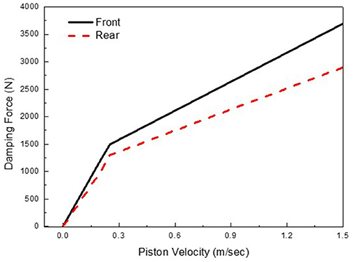
Figure 1. Required damping force characteristics of passenger vehicle.
The originality of this study lies in demonstrating the superior ride quality achieved by using two different types of MR dampers as opposed to one. To achieve this aim, two MR dampers, applicable to middle-sized passenger cars, are considered based on a mathematical model. Prior to investigating the ride comfort, the field-dependent damping force characteristics of two MR dampers were evaluated via simulation, and a full car mathematical model was derived. A sliding mode controller was then designed. Vibration control performance and ride quality were then investigated and evaluated under two different road profiles: bumps, and random road excitations. The reductions in both body displacements and body accelerations in the ride comfort of a vehicle equipped with two different types of MR dampers is significantly improved compared to with one using the same type of MR dampers.
MR Damper
MR Damper Without Orifice Holes
Figure 2 shows the configuration of a cylindrical-type MR damper. The MR damper can be divided into upper and lower chambers, and it is filled with MR fluid. The MR fluid flows from one chamber to the other through the orifice. The gas chamber acts as an accumulator for absorbing sudden pressure variations in the lower chamber of the MR damper induced by the fast motion of the piston. By neglecting frictional forces, the damping force of the MR damper can be written as follows:
where xp and ẋp are the piston displacement and velocity, respectively.
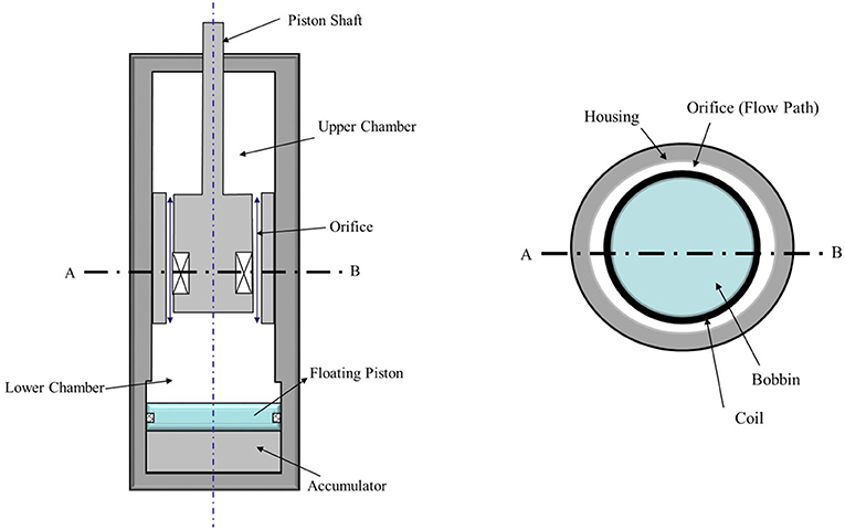
Figure 2. Schematic configuration of conventional MR damper.
The first term in Equation (1) represents the spring force from the gas compliance, and the spring constant of the air chamber can be expressed as follows (Choi and Han, 2012):
where Ar is the piston-rod area; P0 and V0 are the initial volume and pressure of the gas chamber, respectively; Cg is the gas compliance in the gas chamber;κ is the specific heat ratio.
The second term in Equation (1) represents the damping force due to the viscosity of the MR fluid. The viscous damping force of the damper is as follows:
where Ap and Ar are the cross-sectional areas of the piston and piston head, respectively; ΔP is the pressure difference between the upper and lower chambers; hf is the head loss induced by the viscous friction force. As mentioned earlier, the MR fluid flows through the gap and the orifice holes. Therefore, the head loss for the annular duct and orifice holes should be derived. Initially, the annular duct flow is assumed as the flow of a duct between two parallel plates (Choi and Han, 2012). This assumption is valid because the radius of the duct is greater than the radius of the gap. From this assumption, the head loss for the annular duct is as follows:
where fduct, Dduct, and Lduct are the friction coefficient, the diameter, and the length of the duct, respectively; Vduct is the flow velocity through the duct; η is the viscosity constant of the MR fluid. As the total flow rate is identical to the flow rate at the orifice, the velocity of the duct and the viscous damping force can be obtained as follows:
The third term in Equation (1) is deduced from the yield stress of the MR fluid, which can be controlled by the magnitude of the magnetic field. This phenomenon is due to the polarization induced in the particles by applying a magnetic field. The induced dipoles cause the particles to form columnar structures parallel to the applied magnetic field. This phenomenon increases the restriction in the flow direction. To describe the rheological behaviors of MR fluids, the Bingham model is adopted as follows:
where τy(B) is the yield shear stress and is a function of the magnetic flux density, B. This function can be expressed by the polynomial function of magnetic intensity, H. It is known that [a0, a1, a2, a3, a4, a5, a6] = [−155.548 328630593 −277283388 119373779 −27459273 3198253 −146313.95]. In this study, the commercial MR fluid (RMS Corp., MRF 500CP) was used. Based on the Bingham model, the controllable damping force induced from the yield stress of the MR fluid can be represented as follows:
where Lm is the length of the magnetic pole; hm is the gap between the magnetic poles; c is the coefficient dependent on the flow velocity profile and has a value of 2.0–3.0.
MR Damper With Orifice Holes
The schematic configuration of the proposed MR damper utilizing an orifice hole is shown in Figure 3. The piston head comprises a bobbin, orifice holes, and a coil. The MR fluid flows through the orifice hole and the gap between the bobbin and the outer housing of the piston head. As the orifice hole is closer to the center of the non-magnetic hollow cylinder than the coil, the magnetic flux induced from the coil is mainly applied to gap. Since the magnetic field has little effect on orifice hole, the viscous damping force model of OMRD is different with that of MRD. More information related to magnetic analysis can be found in our previous study (Sohn et al., 2015; Park et al., 2016). Since the MR fluid of the OMRD flows through the annular duct and orifice holes, the head loss for the orifice hole is represented as follows:
where fby, Dby, and Lby are the friction coefficient, the diameter, and the length of the orifice hole, respectively. Particularly, the other components of damping force model are identical to Equation (1). As the inlet and outlet for the annular duct and orifice hole are identical, the velocities of the annular duct (Vduct) and the orifice hole (Vby) are obtained as follows:
By substituting Equations (8, 9) into Equation (3), the damping force induced by the viscous friction force is represented as follows:
From the obtained viscous damping force model in Equations (5, 10), it is observed that the obtained viscous damping force of the OMRD is smaller than that of the MRD. In addition, when magnetic input is applied to the coil, and the damper is moved at a low piston velocity, it is difficult for the MR fluid to flow in the annular duct. The viscous damping force in the orifice hole is expressed as follows:
The orifice holes are located close to the center of the bobbin to avoid the MR fluid effect on the flow motion through the orifice hole. When magnetic input is applied to the MR damper, fluid friction induced from yield stress makes the MR fluid flow via only the orifice hole. However, at high piston velocity, the viscous damping force in the orifice hole is larger than the viscous and the controllable damping force in the orifice, as shown in Figure 4. Therefore, the total damping force of the (OMRD) is expressed as follows:
where min() means the minimum value between two damping forces. More information regarding this can be found in our previous study (Sohn et al., 2015; Park et al., 2016).
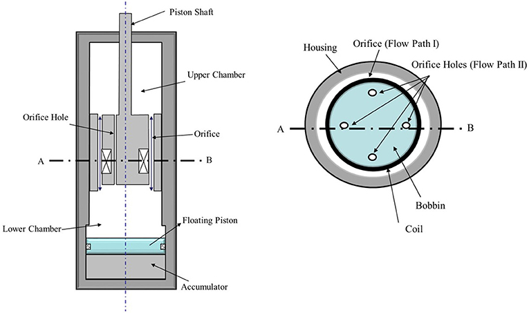
Figure 3. Schematic configuration of MR damper with orifice hole.
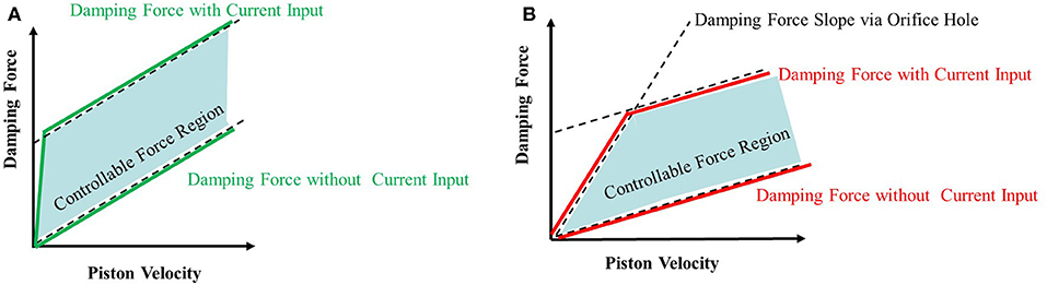
Figure 4. Damping force characteristics of MR damper (A) conventional MR damper (B) MR damper with orifice hole.
Characteristics of Damping Force
From the damping force models in Equations (1, 12), analytical calculations were implemented on a personal computer for MRD and OMRD. Appropriate design parameters were obtained to generate a maximum damping force of 4,000 N, which is the required damping force for a middle-sized passenger car. Design parameters were selected based on an input current of 3 A. The properties of the MR fluid and the design specifications of MR dampers are presented in Table 1. To reasonably compare the ride comfort of the vehicle under the different conditions, all design parameters of the two dampers were identical, except for the orifice holes. The number of orifice hole is 4, and the diameter of the orifice hole is 2.5 mm.
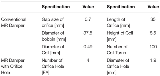
Table 1. Design parameters of MR dampers.
Figures 5A–C shows the calculated damping force curves. Firstly, under the same input current, the maximum damping force of the OMRD is lower than that of the MRD. The maximum damping forces of each damper are 4,238 N, 3,890 N, and 3,657 N, respectively. Additionally, the damping force gradients at 0 A are 1,534 N·s/m, 1,303.5 N·s/m, and 1,148 N·s/m, respectively. This is the result of the additional flow rate via the orifice holes, which are not affected by the input current, reducing the damping force. It can be inferred from these results that the orifice hole limits the maximum damping force. However, this does not imply that the damping force can be controlled by orifice holes. Secondly, parameter study of MR damper with orifice hole had been conducted and the results can be found in our previous study (Sohn et al., 2015). From previous study results, the number of orifice holes is considered as dominant factor among many design parameters. From Figure 5, it is known that the damping force of OMRD is smaller than that of MRD. Also, the low damping characteristic is generally known as essential for superior ride quality (Els et al., 2007). So, it can be expected that MR damper with many orifice hole ensure good ride quality. Although the main objective of this work is to evaluate the ride quality of MRD and OMRD, optimal design of MR damper related to damping capability also very important for commercialization so it will be conducted as a future study. Thirdly, Figures 5B,C show that the orifice holes reduce the occurrence of sudden increases in the field-dependent damping force at low piston velocities. In other words, the damping force with 4 orifice holes is smaller than that with 2 orifice holes. The maximum difference in damping force is 1831.5 N at low velocity (approximately 0.05 m/sec) at 3 A. This difference in the trend of damping force controllability by the magnitude of the current will result in different ride qualities for the vehicles. Accordingly, in order to compare the performance in ride quality, MRD and OMRD with 4 orifice holes will be considered at next chapter.
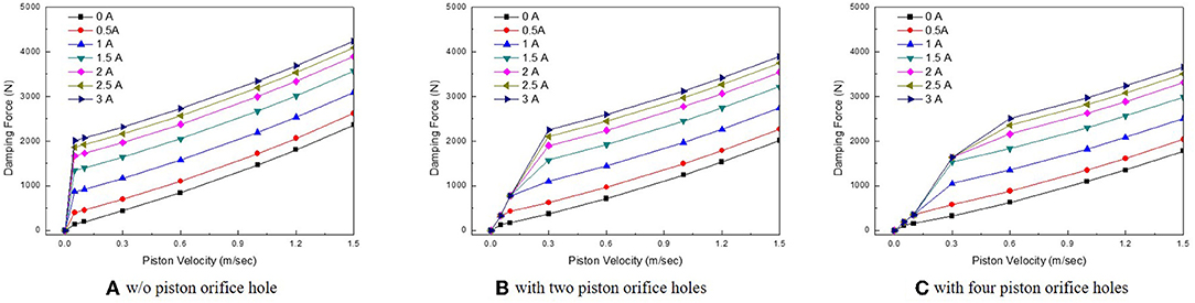
Figure 5. Simulated field-dependent damping force (A) w/o piston orifice hoel (B) with two piston orifice holes (C) with four piston orifice holes.
Performance Evaluation of Ride Comfort
As discussed earlier, as the front and rear wheels experience different static loads because of weight distribution, different values are applied. Therefore, it is anticipated that the required damping force characteristics of the front or rear suspension are in agreement with those of the MRD or OMRD. To investigate this, different vehicle case studies were conducted:
Vehicle I: Four identical MRDs are installed for the front and rear suspension.
Vehicle II: Two MRDs (or two OMRDs) are installed for the front (or rear) suspension.
In addition, a robust sliding mode controller was designed and applied identically to all vehicles. By comparing the control performance, we aim to demonstrate the effectiveness of the proposed method.
Vehicle Suspension System
The mathematical model of the full car system with four MR shock absorbers is constructed as shown in Figure 6. The vehicle body (sprung mass) is assumed to be rigid and has three degrees of freedom (vertical, pitch, and roll directions). The sprung mass is connected to four unsprung masses that have a vertical degree of freedom. The full car model includes body bounce (zg), body roll (φ), body pitch (θ), wheel hop (z1, z2, z3, and z4), and independent road excitations (r1, r2, r3, and r4). The ride comfort of a passenger could be significantly affected because of the vibrations in the bounce, pitch, and roll directions. Therefore, in this study, the design configuration of the proposed MR damper and controllers was simulated to consider these multiple vibration modes. From Figure 6, the governing equations of motion are derived as follows (Jazar, 2017):
where M is the sprung mass; mf and mr are the front and rear unsprung masses, respectively; Ix and Iy are the longitudinal and lateral mass moments of inertia, respectively; kf and kr are the front and rear suspension stiffness constant, respectively; kt is the tire stiffness; cf and cr are the front and rear suspension damping coefficients, respectively; and a1, a2, b1, and b2 are the distances from the center of gravity to each sprung mass and shock absorber.
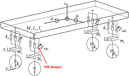
Figure 6. Mechanical model of a full passenger vehicle system with MR dampers.
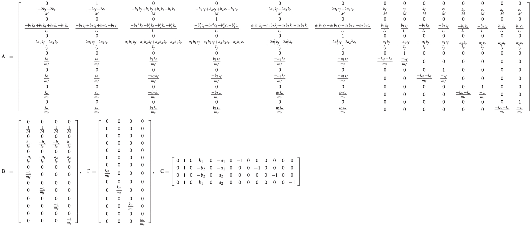
By defining the state vector of the vehicle dynamic system as X = , the state space model for the vehicle dynamic system can be rewritten as follows:
Where A, B, Γ, C, U, and Dare defined in Appendix 1. Yis the piston velocity matrix of each damper. Table 2 presents the mechanical properties of the vehicle system, and in it the spring and damping properties of the front and rear suspensions are different.
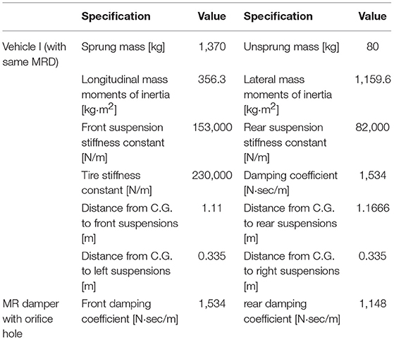
Table 2. Parameters of passenger vehicle system.
Controller Design
To evaluate the control performance, a sliding mode controller (SMC), which has an inherent robustness against system uncertainties and disturbances (Edwards and Spurgeon, 1998; Utkin et al., 1999), was designed. Before designing the SMC, multiple inputs of the vehicle system in Equation (13) are transformed as follows:
To regulate the generalized inputs, the sliding surfaces are designed as follows:
A control law must be selected to drive the system state to the sliding surface s = 0, in which the following reachability condition is satisfied:
where η is a strictly positive constant. To satisfy the reachability condition in Equation (17), the control input is determined as follows:
where sgn(·) is a signum function andki is the discontinuous gain which is designed to overcome the uncertainty of the passenger vehicle system. The left side of Equation (16) is expressed as follows:
Therefore, to ensure that the condition (17) holds, the discontinuous control gain in Equation (18) is chosen as follows:
Moreover, the signum function is switched with a saturation function to avoid the problem of chattering:
where ε is the boundary layer width of the saturation function. Finally, the control input voltage is determined as follows:
Then the generalized inputs are transformed to original inputs of the vehicle system via the inverse matrix of T.
The block diagram of the control strategy is shown in Figure 7, from which the minimum and maximum damping forces are calculated based on the damping force model and piston velocity. When the desired damping force is obtained from the sliding mode controller in Equation (22), the final damping force is determined by comparing the minimum and maximum values.
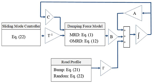
Figure 7. Block diagram of semi-active vehicle system.
Results and Discussions
The MR suspension system should be installed on an actual vehicle and its effectiveness for ride comfort should be evaluated under various road conditions. However, it is expensive to manufacture a full vehicle system from scratch with hardware. Therefore, the ride quality performance and MR dampers are evaluated by computer simulation. A number of previous studies have reported that simulation results are in relatively good agreement with field test results (Seong et al., 2011, 2012; Park et al., 2016).
In this study, suspension control performance was evaluated under two types of road conditions. The first excitation, which is typically used to reveal the transient response characteristics, is a bump described by:
where zb is half of the bump height (0.035 m), and D is the width of the bump (0.8 m). In the bump excitation, the vehicle crosses the bump at a constant vehicle velocity of 40 km/h (11.12 m/s). The second type of road excitation is a stationary random process with zero mean, described by White (1994):
where Wn is the white noise with intensity ; ρr is the road roughness parameter, 0.45 m−1; σ2 is the covariance of white noise, 300 mm2. For random excitations, the road irregularity values were chosen by supposing that the vehicle drives on a paved road at a constant velocity of 72 km/h (20 m/s).
Figures 8, 9 show road bump responses under road bump excitation. It is typically accepted that the acceleration of the sprung mass is used to evaluate ride comfort. As seen in Figure 8, unwanted vibrations induced from the bump excitations have been significantly reduced by adopting the different damper combinations. It was also observed from the vertical displacement of the sprung mass, vertical acceleration of the sprung mass, pitch angle, and roll angle that the ride comfort of Vehicle II is superior to that of Vehicle I.
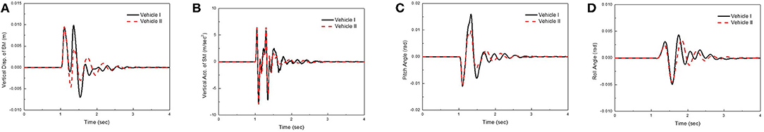
Figure 8. Bump road responses at 40 km/h (A) vertical displacement (B) vertical acceleration (C) pitch angle (D) roll angle.
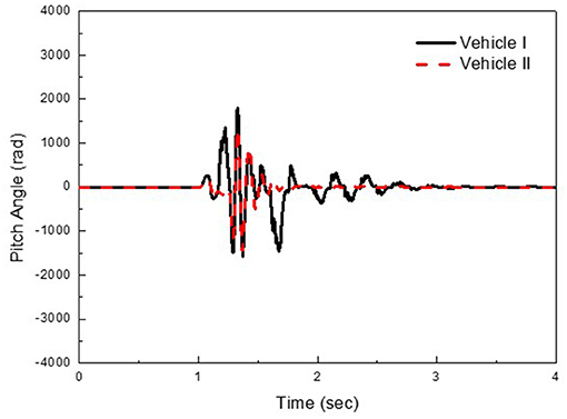
Figure 9. Applied total damping force of rear right damper for bump road responses.
Figure 10 shows random road responses at a constant vehicle velocity of 72 km/h (20 m/s). The power spectral density (PSD) of the vertical acceleration is plotted against frequency. As anticipated, the PSDs for the vertical acceleration of Vehicle II are significantly decreased compared to those of Vehicle I, from 2.62 to 0.1364 (m/s2)2/Hz at 3.1 Hz. The suspension control performances shown in Figures 8–10 indicates that the ride comfort of the vehicle can be simultaneously improved by employing two front MRDs and two rear OMRDs.
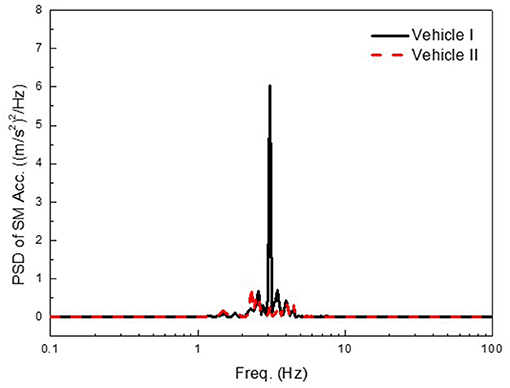
Figure 10. Random road responses at 72 km/h.
Conclusion
In this study, the ride comfort of passenger vehicles equipped with different combinations of front/rear suspension systems featuring two different types of MR dampers, with and without orifice holes, were compared. To achieve this aim, the damping force model of the two different MR dampers were analyzed. It was observed that the OMRD exhibited a smaller damping force than the MRD. To evaluate the ride quality, a robust sliding mode controller was designed. It was demonstrated that displacement, acceleration of the vehicle body, and pitch angle could be significantly reduced by activating the MR dampers under two road conditions: bumps, and random roads. In particular, it was shown that the ride quality performance of the vehicle with different damper combinations was superior to that of a vehicle with the same type of MR dampers. This was because of the small damping force in the low piston velocity range. In other words, by eliminating sudden increases in the field-dependent damping force, smooth and comfortable vehicle motions are obtained. In the second phase of this study, two semi-active MR dampers will be manufactured, and the ride comfort of both will be tested under various road conditions.
Author Contributions
All authors listed have made a substantial, direct and intellectual contribution to the work, and approved it for publication.
Conflict of Interest Statement
The authors declare that the research was conducted in the absence of any commercial or financial relationships that could be construed as a potential conflict of interest.
Acknowledgments
This work was supported by the Technology Innovation Program (Intelligent landing gear with variable damping force for 1500lb class) (10073291) funded by the Ministry of Trade, Industry & Energy (MOTIE, Korea).
References
Ahmadian, M., and Pare, C. A. (2000). A quarter-car experimental analysis of alternative semiactive control methods. J. Intell. Matreial Syst. Struct. 11, 604–612. doi: 10.1106/MR3W-5D8W-0LPL-WGUQ
Albinsson, A., and Routledge, C. (2019). The Damper Levels Influence on Vehicle Roll, Pitch, Bounce and Cornering Behaviour of Passenger Vehicles. Master's thesis in automotive engineering, Department of Applied Mechanics, Division of Vehicle Engineering and Autonomous Systems, Chalmers University of Technology, Sweden.
Bai, X., Hu, W., and Wereley, N. M. (2013). Magnetorheological damper utilizing an inner bypass for ground vehicle suspensions. IEEE Trans. Magnetics 49, 3422–3425. doi: 10.1109/TMAG.2013.2241402
Brigley, M., Choi, Y. T., and Wereley, N. M. (2008). Experimental and theoretical development of multiple fluid mode magnetorheological isolators. J. Guidance Control Dyn. 31, 449–459. doi: 10.2514/1.32969
Carlson, J. D., Cantanzarite, D. M., and St. Clair, K. A. (1996). Commercial magneto-rheological fluid devices. Int. J. Modern Phys. B. 10, 2857–2865. doi: 10.1142/S0217979296001306
Choi, S. B., and Han, Y. M. (2012). Magnetorheological Fluid Technology Applications in Vehicle Systems. Padstow: CRC Press Taylor and Francis Group.
Choi, S. B., Lee, H. K, and Chang, E. G. (2001). Field test results of a semi-active ER suspension systems associated with skyhook controller. Mechatronics 11, 345–353. doi: 10.1016/S0957-4158(00)00022-2
Choi, S. B., Seong, M. S., and Ha, S. H. (2009). Vibration control of an MR vehicle suspension system considering both hysteretic behavior and parameter variation. Smart Mater. Struct. 18:125010. doi: 10.1088/0964-1726/18/12/125010
Choi, S. B., and Sung, K. G. (2008). Vibration control of magnetorheological damper system subjected to parameter variations. Int. J. Vehicle Design 45, 94–110. doi: 10.1504/IJVD.2008.017071
Dyke, S. J., Spencer, B. F., Sain, M. K. S., and Carlson, J. D. (1996). “A new semi-active control device for seismic response reduction,”in Proceeding of 11th ASCE Engrg. Mech. Spec. Conf. ASCE (Fort Lauderdale, UL), 886–889.
Els, P. S., Theron, N. J., Uys, P. E., and Thoresson, M. J. (2007). The ride comfort vs. handling compromise for off-road vehicles. J. Terramech. 44, 303–317. doi: 10.1016/j.jterra.2007.05.001
Georgiou, G., and Natsiavas, S. (2009). Optimal selection of suspension parameters in large scale vehicle models. Vehicle Syst. Dyn. 47, 1147–1166. doi: 10.1080/00423110802531075
Hong, S. R., Wang, G., Hu, W., Wereley, N. M., and Choi, S. B. (2007). “Hydro-mechanical Analysis of a Magnetorheological Bypass Damper,” Proceedings of the 10th International Conference on Electrorheological Fluids and Magnetorheological Suspensions. (Singapore, World Scientific Publishing Company). 438–444.
Park, J. H., Kim, W. H., Shin, C. S., and Choi, S. B. (2016). A comparative work on vibration control of a quarter car suspension system with two different magneto-rheological dampers. Smart Mater. Struct. 26:015009. doi: 10.1088/1361-665X/26/1/015009
Poussot-Vassal, C., Sename, O., Dugard, L., Ramirez-Mendoza, R., and Flores, L. (2006). Optimal skyhook control for semiactive suspensions. IFAC Proc. 39, 608–613. doi: 10.3182/20060912-3-DE-2911.00106
Seong, M. S., Choi, S. B., and Kim, C. H. (2011). Design and performance evaluation of MR damper for integrated isolation mount. J. Intell. Mater. Syst. Struct. 22, 1729–1738. doi: 10.1177/1045389X11421820
Seong, M. S., Choi, S. B., and Lee, Y. S. (2012). Vibration control of quarter vehicle magnetorheological suspension using preisach hysteretic compensator. Adv. Sci. Lett. 13, 540–546. doi: 10.1166/asl.2012.3883
Sohn, J. W., Oh, J. S., and Choi, S. B. (2015). Design and novel type of a magnetorheological damper featuring piston bypass hole. Smart Mater. Struct. 24:035013. doi: 10.1088/0964-1726/24/3/035013
Sung, K. G., and Choi, S. B. (2012). Magnetorheological fluid shock absorber for electronic control suspension of a passenger vehicle. Adv. Sci. Lett. 14, 495–498. doi: 10.1166/asl.2012.3982
Sung, K. G., Seong, M. S., and Choi, S. B. (2013). Performance evaluation of electronic control suspension featuring vehicle ER dampers. Meccanica 48, 121–134. doi: 10.1007/s11012-012-9588-4
Sunwoo, M. H., Cheok, K. C., and Huang, N. J. (1991). Model reference adaptive control for vehicle active suspension system. IEEE Trans. Industr. Electr. 38, 217–222. doi: 10.1109/41.87590
Utkin, V., Guldner, J., and Shi, J. (1999). Sliding Mode Control in Electromechanical Systems. London; Boca Raton, FL: CRC Press.
Yao, G. Z., Yap, F., Chen, G., Li, W. H., and Yeo, S. H. (2002). MR damper and its application for semi-active control vehicle suspension system Mechatronics 12, 963–973. doi: 10.1016/S0957-4158(01)00032-0
Appendix I
Keywords: magnetorheological fluid, MR damper with orifice hole (OMRD), ride quality, damping force, sliding mode controller, passenger vehicle
Citation: Oh J-S and Choi S-B (2019) Ride Quality Control of a Full Vehicle Suspension System Featuring Magnetorheological Dampers With Multiple Orifice Holes. Front. Mater. 6:8. doi: 10.3389/fmats.2019.00008
Received: 30 November 2018; Accepted: 15 January 2019;
Published: 04 February 2019.
Edited by:
Ilkwon Oh, Korea Advanced Institute of Science & Technology (KAIST), South KoreaReviewed by:
Hargsoon Yoon, Norfolk State University, United StatesYoungjae Chun, University of Pittsburgh, United States
Taihong Cheng, Wenzhou University, China
Copyright © 2019 Oh and Choi. This is an open-access article distributed under the terms of the Creative Commons Attribution License (CC BY). The use, distribution or reproduction in other forums is permitted, provided the original author(s) and the copyright owner(s) are credited and that the original publication in this journal is cited, in accordance with accepted academic practice. No use, distribution or reproduction is permitted which does not comply with these terms.
*Correspondence: Jong-Seok Oh, am9uZ3Nlb2tAa29uZ2p1LmFjLmty
Seung-Bok Choi, c2V1bmdib2tAaW5oYS5hYy5rcg==