 Do Xuan Phu
 Seung-Bok Choi
- 1MediRobotics Laboratory, Department of Mechatronics and Sensor Systems Technology, Vietnamese-German University, Ho Chi Minh City, Vietnam
- 2Smart Structures and Systems Laboratory, Department of Mechanical Engineering, Inha University, Incheon, South Korea
This paper presents a mini-review of magnetorheological (MRF) fluid-based devices (MRF devices in short) including the brake, clutch, damper, and the mount reported from 2013 to 2018. MRF devices are usually designed based on three operating modes of MRF: flow mode, shear mode and squeeze mode. Each mode has its own characteristics for the high performance of application systems. Therefore, numerous design configurations of MRF devices have been proposed by many researchers. In this article, among many different MRF devices such as MRF brake, clutch, damper and MRF mount proposed over the last 6 years are examined in the sense of their structural configuration and operating principles. Certain advantages and demerits of each MRF device are also discussed. In addition, some useful design guidelines of MRF devices, which are absolutely different from developed MRF devices so far, are provided to enhance design simplicity and control performance.
Introduction
Magnetorheological fluid (MRF) is known as an attractive smart material which can be widely utilized to develop devices in various industries including automotive engineering, aerospace engineering, the manufacturing industry and medical fields. Specific application devices are the damper (or shock absorber), brake, clutch, mount, the prosthetic leg, and lower-limb exoskeleton. The first device which was commercialized is the shock absorber for a vehicle suspension system which can adaptively control unwanted vibrations induced by road conditions. There are several reasons why MRF devices are attractive to many different researchers. Those include reversible property between liquid phase and solid phase, low power consumption (around 2–5 Watt for the vehicle damper), fast response time (< 10 ms) and design simplicity with the magnetic core only. In terms of the rheological characteristics, the magnitude of the storage and loss modulus are controlled by the intensity of the magnetic field to be applied to the fluid domain. In addition, one unique merit of an MRF device, which does not exist in conventional devices such as servomotor and hydraulic devices, is the fail-safe function. In other words, MRF devices can provide passive device performance, even when it fails during control action. This is possible since an MRF device has a carrier liquid which is equivalent to the viscous oil frequently used in passive devices. This unique feature is attractive for numerous application and systems utilizing MRF devices.
Among numerous MRF device-based mechanisms, in this review article MRF brake, clutch, damper, and MRF mount are examined in terms of their design configurations and operating principles. These MRF devices are chosen since they can apply to many different systems such as the vibration control of an automobile, vibration control of seismic, and several different rehabilitation prosthetics. An MRF brake and clutch can be applied to vehicles, automatic conveyer tables, vibration control cables, prosthetic legs, and rotation mechanisms such as a robot joint. An MRF damper can be applied to an automotive suspension system, the vibration control of seismic, the vibration control of a washing machine, the vibration control of flexible structures and the vibration control of mechanisms of the civil engineering field such as a vibration absorber of a very tall building or a long bridge. An MRF mount is very useful to control unwanted vibrations which occur in most dynamic systems in which an MRF damper cannot be installed due to the lack of space. For example, a mount for a vehicle engine, a wheel loader, a precision stage and a mount for a compact disk rom.
In this review article, newly developed MRF devices, in their third stage of practical application is examined by focusing on the design configuration and showing principal components. Some advantages and disadvantages of each MRF device are discussed in terms of design and control. Moreover, some drawbacks of sedimentation, leakage and durability of MRF filled in the devices are also reviewed. Prior to concluding the article, some advanced MRF devices, which can avoid existing impediments, are suggested by drawing a conceptual design configuration. This article will be very helpful to understand the specific design methods of major MRF devices and provide very useful guidelines for MRF devices which can be practically realized in the field.
MRF Brake and MRF Clutch
Design of an MRF brake/clutch uses two modes of MRF: flow mode and shear mode. If the core is rotated and the housing is fixed, the design is called an MRF brake, and inversely its name is n MRF clutch. The torque level of the brake and clutch is controlled by controlling the input current (or magnetic field intensity). Therefore, very accurate torque transmission and stopping can be achieved by a simple, but very effective MRF device. The MRF brake and clutch, developed during 2013–2018, is summarized in Table 1. In 2013, most design types of the MRF brake and clutch were classified by four configurations: multi-disc, multi-plate, multi-gap and multi-coil (pole). Basically, these design methods are easy to fabricate because it only includes the disc or the coil. In 2014, a different design for the MRF brake was presented (Nguyen et al., 2014) in which the housing structure was modified to optimize the magnetic line. This design methodology was breakthrough in the design of MRF devices in the sense of the minimization of housing material. In this design method, the torque level is similar to the conventional one, but the manufacturing cost is reduced substantially. In 2015, a new model of the MRF brake was proposed based on the changeable structure of the electric or/and magnetic coil (Nguyen et al., 2015). This was made possible by placing the electric coil at the outside of the housing. In 2016, a new combination of permanent magnetic and MRF for MRF brake design has been reported in Yu et al. (2017). It has been shown that the torque control performance of this design method is good, but the practical realization is difficult due to the large size of the permanent magnet and the housing. Moreover, the assembly and maintenance of each components is not easy. In 2017, a new design method for the MRF clutch was reported (Rizzo, 2017). In this design method, the permanent magnet was used to control the magnetic field of the clutch. The magnitude of torque varied following the position of the magnet. In the off-state, the position of the magnet does not contact the MRF area using the spring. In the on-state, the position of the magnet is moved to the MRF area by the expansion of the spring. It is therefore efficient to control the rotational motion of the connected MRF devices. One unique feature of this design method is the increase of the torque level with the same magnetic field and also the prevention of the block-up phenomenon, in which the flow motion of the MRF does not occur. In 2018, no new design configuration of the MR brake and clutch has been proposed. However, the research work on the reduction of the saturation problem of the magnetic materials was actively undertaken.
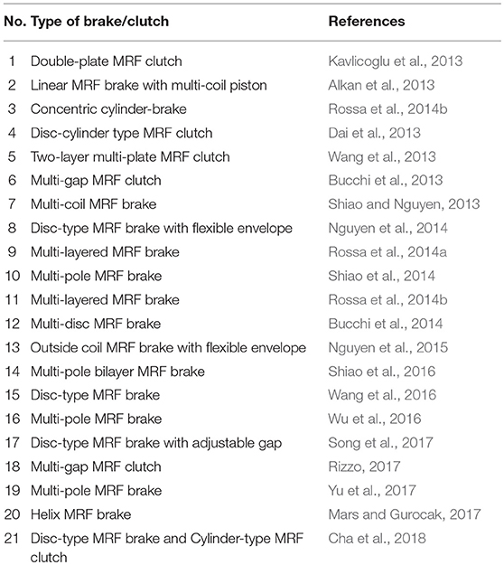
Table 1. Studies of MRF brake and MRF clutch in 2013–2018.
In this review article, two specific design configurations of the MRF brake device are examined in more detail. Figure 1 shows the design schematic of the MRF brake with multi-coils (Shiao and Nguyen, 2013). In this design, the multi-coil housing is used and the design concept was inspired from the configuration of the electric motor. The magnetic field in the coils control the state of the MRF from the liquid phase to solid phase, or vice versa, which is arranged in the central rod of the brake. In this brake design, the housing with the coils is always fixed. The advantages of the multi-coil brake include the increase of efficiency of the magnetic line and the separated control of every coil. However, this design may increase the manufacturing costs associated with its relatively large size. Moreover, the collision of magnetic lines among electrical coils may occur and making the torque level similar to the conventional disc type of the brake. Figure 2 shows a type of MRF brake called a helix cylinder (Mars and Gurocak, 2017). The unique feature of this design is to shape the core of the MRF brake to the helix cylinder. By doing this, the volume of the MRF can be reduced, while also maintaining the high levels of the braking torque in the presence of a magnetic field. In fact, in this design method, the core plays an important role in the MRF brake. The air is used as an accumulator which prevents the shock vibration and supports the damping coefficient of the MRF device. This design configuration has a simple structure, but several problems need to be resolved. The first disadvantage of this design is the need for accurate manufacturing of the core part which subsequently increases the cost. Another demerit is that the flow motion of the MRF is not smooth, due to the shape of the helix gap. Moreover, high performance devices are required to maintain air pressure.
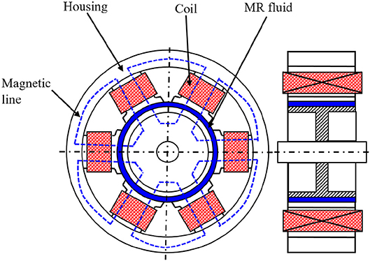
Figure 1. Design of multi-coil MRF brake (Shiao and Nguyen, 2013).
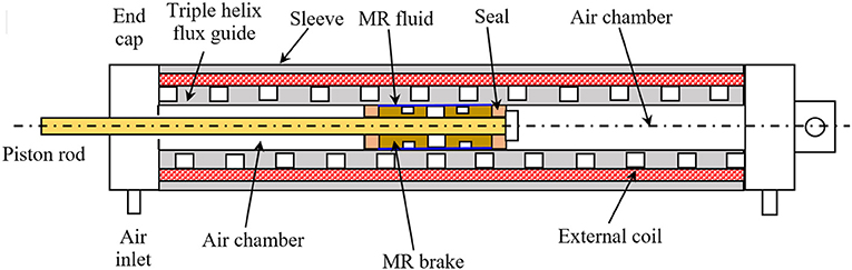
Figure 2. MRF brake with helix housing design (Mars and Gurocak, 2017).
MRF Damper
When designing a damper, three modes of MRF is used such as flow, shear and squeeze modes. The specific design configurations of the MRF damper are summarized in Table 2. It can be seen from the table that the piston-type MRF damper has a structural design, in which the flow mode predominantly occurs to generate the field-dependent damping force. It can be noted here that the damping force subjected to the shear mode is smaller than that operated with the flow mode under the same design constraints. However, the MRF damper operated with the squeeze mode, can provide a larger damping force than when operated with the flow mode, due to the small stroke. The multi-coil type damper is also very effective in terms of the magnitude of the field-dependent damping force, since the magnetic coils can easily be optimized to have maximum magnetic field distribution. In 2014, three different features of the MRF damper were introduced. The first design configuration was proposed in McLaughlin et al. (2014) where the MRF valve, associated with the spiral core, to manage the flow of MRF was used. One of the merits of this structural configuration is to have a smooth flow motion of MRF in the gap since there is no obstruction in the flow path. The second type of MRF damper was fabricated on the basis of the squeeze mode (Yazid et al., 2014). One salient property of this type, is to have a high damping force compared with the type of the flow mode. However, the squeeze mode MRF damper type cannot be applied to dynamic systems, which have a large moving stroke due to the difficulty of the sealing. The third type of MRF damper was devised considering both the permanent magnetic and electrical coil (Sapinski, 2014). This type is a special device for energy harvesting purposes instead of vibration control. One drawback of this type is the design complexity, due to many parts of both the housing and the core. In 2015, a new damper using metal foams embedded MRF was introduced to save the volume of MRF (Liu et al., 2015). The design configuration is unique, but its performance is poor, due to the high friction between the core and the foam. In 2016, a new MRF damper consisting of a mechanical spring, in combination with the damper was proposed, to support the required static force in vibration control (Powell et al., 2016). The main function of the spring is to act as a door to open or close the valve embedded in the center of the core piston. In 2017, a new MRF damper, activated by the permanent magnets instead of the magnetic coils was introduced (Kim et al., 2017). In this damper, the capability of the field-dependent damping force control is achieved through a special arrangement of the permanent magnets. In other words, the damping force can be controlled by moving the position of the permanent magnets, to magnetize different areas. It should be noted that the MRF damper, activated by the permanent magnets, can be manufactured with a cheaper cost compared with the magnetic coil operated MRF damper, but the damping force induced from the magnetic field is lower than the conventional MRF damper. Therefore, optimizing the shape of the permanent magnets needs to be researched in order to increase the field-dependent damping force.
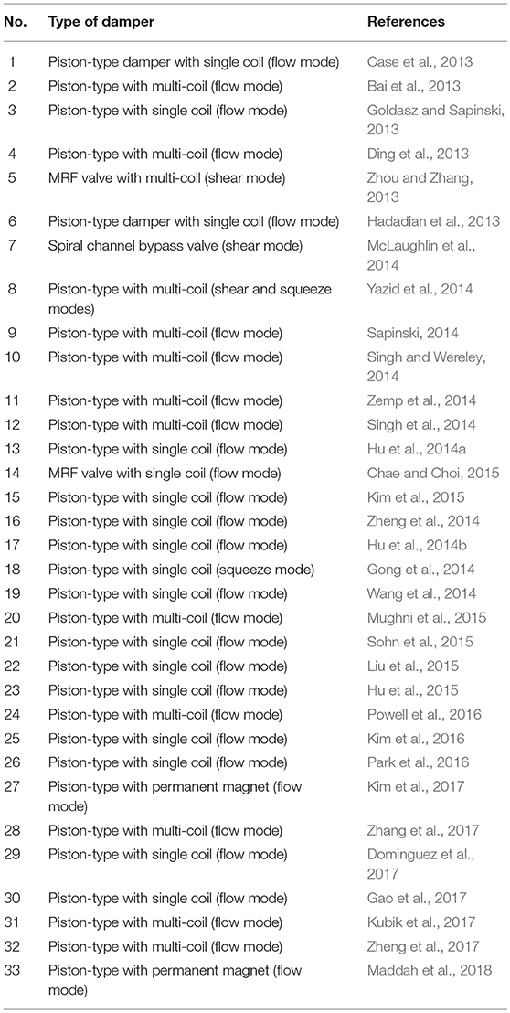
Table 2. Studies of MRF damper in 2013-2018.
In this review article, two different types of MRF dampers are specifically examined with regards to their design structures. Figure 3 presents a hybrid damper (Powell et al., 2016). This design uses a combination of a valve and a multi-coil core. The difference of upper pressure and lower pressure of the damper is adjusted by the valve with the mechanical spring. The flow of MRF is not blocked, which is an advantage of the design. When the core damper is moved up, the valve will be closed. In this case, the pressure of the upper chamber is larger than the lower chamber. The damping force is also increased to control vibration. After that, the core of the damper is moved down, the valve is opened, and the pressure of both chambers is balanced. The force in this time is smaller than the former. Figure 4 shows the MRF damper, in which the magnetic distribution can be adjusted by making an inclined gap (Zheng et al., 2017). When the core is moved, the damping force is also changed. When the core is moved to the left, the damping force obtains the maximum value to control vibration. The pressure of the left chamber is larger than the right chamber. Inversely, the force is smaller than the above movement. It has been shown that the block up phenomenon can be prevented by the inclined gap of the core damper. However, the general force for both designs, (Powell et al., 2016) and (Zheng et al., 2017), is not larger than the conventional design. In addition, the size of the proposed structure is also bigger than the conventional device.
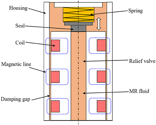
Figure 3. MRF damper with valve and multi-coils (Powell et al., 2016).
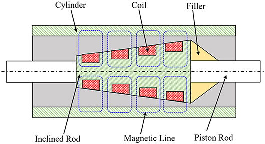
Figure 4. MRF damper with inclined gap and multi-coils (Zheng et al., 2017).
MRF Mount
It is known that the MRF mount is very effective in attenuating a small magnitude and a high frequency of vibrations in many dynamic systems such engine excitation. The flow motion of the MRF mount is the same as that of the MRF damper: flow mode, shear mode and squeeze mode. For the past 6 years, many research works on the MRF mount have been undertaken and some studies are summarized in Table 3. Most design configurations of the MRF mount reported during 2013–2017 feature valve types with more than one operating mode. The main structure used in these years were designed to have the MRF valve type in which the H-gap is the most significant design parameter. The pressure difference between the upper and lower chambers, which is directly related to the field-dependent damping force, is determined by the H-gap. However, these types of MRF mounts have a bottle neck when the H-gap is designed with a very narrow scale. More specifically, the flow motion is stopped in the narrow gap and hence the controllability of the damping force is no longer possible. This is called the block-up phenomenon. In 2014, a breakthrough design of the MRF mount was proposed to avoid the block-up phenomenon (Do et al., 2014) as shown in Figure 5. It is seen from the schematic configuration that a flexible plate is positioned between the upper and lower plates which can change the glow gap depending upon the vibration or excitation magnitudes. In other words, the gap size can be enlarged when the vibration magnitude is large while it can be smaller when the vibration magnitude is very small. By activating this principle, the block-up phenomenon, which appeared in almost all conventional MRF mounts, can effectively be avoided. In addition, a simple design with a low manufacturing cost is possible to meet a certain requirement in many different applications such as an engine mount, bridge mount and an electronic appliance mount. In 2016, a squeeze mount shown in Figure 6 was proposed in (Li et al., 2016). The core component of this type of MRF mount is the chamber containing MRF, in which the squeeze motion (or up and down motions) occurs to produce the field-dependent damping force. In order to achieve an appropriate damping force, the height (or gap) of the chamber needs to be optimized. In general, the gap size of the squeeze mode MRF mount is around 1–2 mm for the application to vehicle engine mount. One drawback of this type is the difficulty in vibration control, with relatively large magnitudes, due to the sealing issue preventing leakage in its practical use, which becomes more serious. Therefore, this type of MRF mount is effective in controlling small excitations with relatively high frequency components. Recently, a new design structure, to avoid the block-up behavior, was proposed (Sakai and Stramigioli Visuali, 2018). In this design, the cores have been modified to balance the pressure of both the upper and lower chamber. In addition, two pistons connected to the vibration plate was used to balance the pressure between the two pistons. Therefore, the block-up behavior can be avoided by properly controlling the pressure difference (or the field-dependent actuating force) through the servo valve system. It is remarked here that recently, a new kind of high-loaded mount using MR elastomer was introduced in Yarra et al. (2018). The mount based on the MR elastomer does not require any fluid reservoir, but the response time is relatively slow.
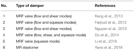
Table 3. Studies of MRF mount in 2013–2018.
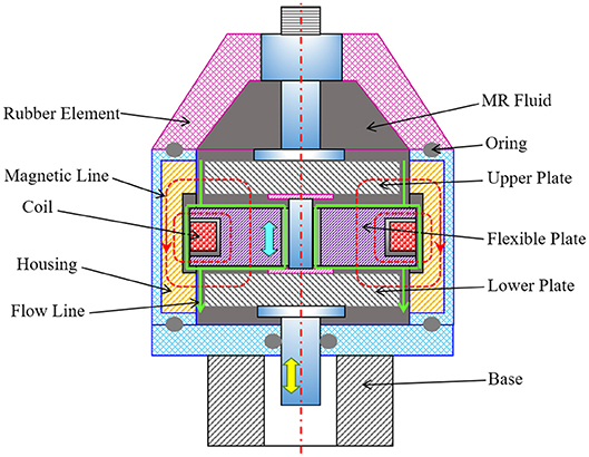
Figure 5. MRF mount with the flexible plate for changeable gap (Do et al., 2014).

Figure 6. MRF mount with the squeeze mode (Li et al., 2016).
Conclusion with Suggestions
In this review article, MR devices reported over the last 6 years (2013–2018) were examined in terms of their design configuration. It was identified that many different structural configurations for the brake, clutch, damper and mount can be devised, when considering the principal operating models: flow, shear and squeeze. Several problems that need to be resolved, for successful practical use, despite some MRF dampers that are commercially available now, still remain. Among these many problems, two of the most significant issues that need to be resolved, for the practical application in many fields, are the avoidance or minimization of the block-up phenomenon and the maximization of the field-dependent actuating force with certain design constraints.
Figure 7 presents a possible design of an MRF device which can produce a high damping force without any block-up phenomenon. In this design structure, the main component is an opened block-chain of the MRF valve. The elastic housing is deformed and then the non-valve elastic joint becomes infinitely stiff in order to absorb the vibrations. Thus, the stiffness of the elastic material will be optimized to control vibrations without causing block-up behavior, by implementing an appropriate controller. Another effective design configuration for the MRF device is to place the magnetic coils on the outside of the housing as shown in Figure 8. Advantages of this design include the independent control of each magnetic line, the adaptiveness to the change of the vibration (or excitation) and the possibility of several segments of different actuating forces to meet the corresponding external disturbances such as unwanted vibrations or noise. It is noted here that successful development of this MRF device type requires both the reliable hardware and accurate software associated with an appropriate controller.
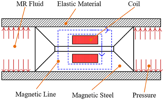
Figure 7. MRF block-chain valve.
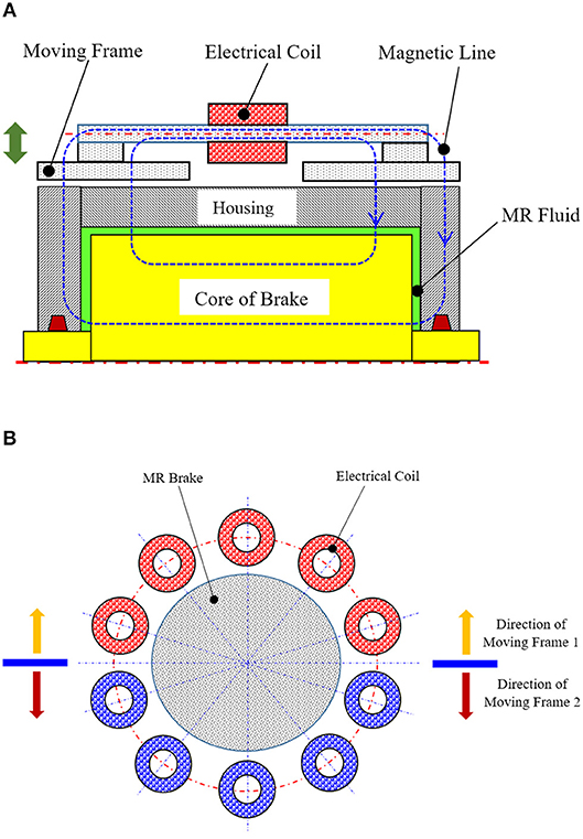
Figure 8. MRF damper with multi-outside coils, (A) general view, (B) view of multi-coils.
Author Contributions
DP conceived and wrote the paper. S-BC analyzed the references and wrote the future directions of the research.
Conflict of Interest Statement
The authors declare that the research was conducted in the absence of any commercial or financial relationships that could be construed as a potential conflict of interest.
Acknowledgments
This research was funded by the Vietnam National Foundation for Science and Technology Development (NAFOSTED) under grant number 107.01-2017.28. This financial support is gratefully acknowledged.
References
Alkan, M. S., Gurocak, H., and Gonen, B. (2013). Linear magnetorheological brake with serpentine flux path as a high force and low off-state friction actuator for haptics. J. Intell. Mater. Syst. Struct. 24, 1699–1713. doi: 10.1177/1045389X13484098
Bai, X. X., Hu, W., and Wereley, N. M. (2013). Magnetorheological damper utilizing an inner bypass for ground vehicle suspensions. IEEE Trans. Magn. 49, 3422–3425. doi: 10.1109/TMAG.2013.2241402
Bucchi, F., Forte, P., Franceschini, A., and Frendo, F. (2013). Analysis of differently sized prototypes of an MR clutch by performance indices. Smart Mater. Struct. 22:105009. doi: 10.1088/0964-1726/22/10/105009
Bucchi, F., Forte, P., Frendo, F., Musolino, A., and Rizzo, R. (2014). A fail-safe magnetorheological clutch excited by permanent magnets for the disengagement of automotive auxiliaries. J. Intell. Mater. Syst. Struct. 25, 2102–2114. doi: 10.1177/1045389X13517313
Case, D., Taheri, B., and Richer, E. (2013). Design and characterization of a small-scale magnetorheological damper for tremor suppression. IEEE/ASME Trans. Mechatron. 18, 96–103. doi: 10.1109/TMECH.2011.2151204
Cha, S. W., Kang, S. R., Hwang, Y. H., Choi, S. B., Lee, Y. S., and Han, M. S. (2018). Design and control of a parallel mechanism haptic master for robot surgery using magneto-rheological clutches and brakes. J. Intell. Mater. Syst. Struct. 29, 3829–3844. doi: 10.1177/1045389X18799477
Chae, H. D., and Choi, S. B. (2015). A new vibration isolation bed stage with magnetorheological dampers for ambulance vehicles. Smart Mater. Struct. 24:017001. doi: 10.1088/0964-1726/24/1/017001
Dai, S. Q., Du, C. B., and Yu, G. J. (2013). Design, testing and analysis of a novel composite magnetorheological fluid clutch. J. Intell. Mater. Syst. Struct. 24, 1675–1682. doi: 10.1177/1045389X13483026
Ding, Y., Zhang, L., Zhu, H. T., and Li, Z. X. (2013). A new magnetorheological damper for seismic control. Smart Mater. Struct. 22:115003. doi: 10.1088/0964-1726/22/11/115003
Do, X. P., Shah, K., and Choi, S. B. (2014). A new magnetorheological mount featured by changeable damping gaps using a moved-plate valve structure. Smart Mater. Struct. 23:125022. doi: 10.1088/0964-1726/23/12/125022
Dominguez, G. A., Kamezaki, M., and Sugano, S. (2017). Proposal and preliminary feasibility study of a novel toroidal magnetorheological piston. IEEE/ASME Trans. Mechatron. 22, 657–668. doi: 10.1109/TMECH.2016.2622287
Farjoud, A., Taylor, R., Schumann, E., and Schlangen, T. (2013). Advanced semi-active engine and transmission mounts: tools for modelling, analysis, design, and tuning. Vehicle Syst. Dyn. 52, 218–243. doi: 10.1080/00423114.2013.870345
Gao, F., Liu, Y. N., and Liao, W. H. (2017). Optimal design of a magnetorheological damper used in smart prosthetic knees. Smart Mater. Struct. 26:035034. doi: 10.1088/1361-665X/aa5494
Goldasz, J., and Sapinski, B. (2013). Verification of magnetorheological shock absorber models with various piston configurations. J. Intell. Mater. Syst. Struct. 24, 1846–1864. doi: 10.1177/1045389X13479684
Gong, X. L., Ruan, X. H., Xuan, S. H., Yan, Q. F., and Deng, H. X. (2014). Magnetorheological damper working in squeeze mode. Adv. Mech. Eng. 2014:410158. doi: 10.1155/2014/410158
Hadadian, A., Sedaghati, R., and Esmailzadeh, E. (2013). Design optimization of magnetorheological fluid valves using response surface method. J. Intell. Mater. Syst. Struct. 25, 1352–1371. doi: 10.1177/1045389X13504478
Hu, G. L., Long, M., Huang, M., and Li, W. H. (2014a). Design, analysis, prototyping, and experimental evaluation of an efficient double coil magnetorheological valve. Adv. Mech. Eng. 2014:403410. doi: 10.1155/2014/403410
Hu, G. L., Long, M., Yu, L., and Li, W. H. (2014b). Design and performance evaluation of a novel magnetorheological valve with a tunable resistance gap. Smart Mater. Struct. 23:127001. doi: 10.1088/0964-1726/23/12/127001
Hu, G. L., Ru, Y., and Li, W. H. (2015). Design and development of a novel displacement differential self-induced magnetorheological damper. J. Intell. Mater. Syst. Struct. 26, 527–540. doi: 10.1177/1045389X14533429
Kang, O. H., Kim, W. H., Joo, W. H., and Park, J. H. (2013). “Design of the magnetorheological mount with high damping force for medium speed diesel generators,” in Active and Passive Smart Structures and Integrated Systems Proc. of SPIE 8688:86881E (San Diego, CA). doi: 10.1117/12.2012831
Kavlicoglu, B. M., Gordaninejad, F., and Wang, X. (2013). Study of a magnetorheological grease clutch. Smart Mater. Struct. 22:125030. doi: 10.1088/0964-1726/22/12/125030
Kim, H. C., Oh, J. S., and Choi, S. B. (2015). The field-dependent shock profiles of a magnetorheological damper due to high impact: an experimental investigation. Smart Mater. Struct. 24:025008. doi: 10.1088/0964-1726/24/2/025008
Kim, K. S., Chen, Z. B., Yu, D., and Rim, C. H. (2016). Design and experiments of a novel magnetorheological damper featuring bifold flow mode. Smart Mater. Struct. 25:075004. doi: 10.1088/0964-1726/25/7/075004
Kim, W. H., Park, J. H., Kaluvan, S., Lee, Y. S., and Choi, S. B. (2017). A novel type of tunable magnetorheological dampers operated by permanent magnets. Sens. Actu. A Phys. 255, 104–117. doi: 10.1016/j.sna.2017.01.012
Kubik, M., Machacek, O., Strecker, Z., Roupec, J., and Mazurek, I. (2017). Design and testing of magnetorheological valve with fast force response time and great dynamic force range. Smart Mater. Struct. 26:047002. doi: 10.1088/1361-665X/aa6066
Li, Z. H., Zhang, X. J., Guo, K. H., and Ahmadian, M. (2016). A novel squeeze mode based magnetorheological valve: design, test and evaluation. Smart Mater. Struct. 25:127003. doi: 10.1088/0964-1726/25/12/127003
Liu, X. H., Gao, X. L., Li, F., Yu, H., and Ye, D. (2015). Shear performance of a metal foam magnetorheological fluid damper. IEEE Trans. Magn. 51:4600107. doi: 10.1109/TMAG.2014.2343938
Maddah, A. A., Hojjat, Y., Karafi, M. R., and Ashory, M. R. (2018). Reduction of magnetorheological dampers stiffness by incorporating of an eddy current damper. J. Sound Vib. 396, 51–68. doi: 10.1016/j.jsv.2017.02.011
Mars, M. C., and Gurocak, H. (2017). Pneumatic cylinder with magnetorheological brake using serpentine and helix flux guide as a linear hybrid actuator for haptics. J. Intell. Mater. Syst. Struct. 28, 1303–1321. doi: 10.1177/1045389X16667562
McLaughlin, G., Hu, W., and Wereley, N. M. (2014). Advanced magnetorheological damper with a spiral channel bypass valve. J. Appl. Phys. 115:17B532. doi: 10.1063/1.4869278
Mughni, M. J., Zeinali, M., Mazlan, S. A., Zamzuri, H., and Rahman, M. A. A. (2015). Experiments and modeling of a new magnetorheological cell under combination of flow and shear-flow modes. J. Nonnewton. Fluid Mech. 215, 70–79. doi: 10.1016/j.jnnfm.2014.11.005
Nguyen, Q. H., Do, X. P., Park, J. H., Choi, S. B., and Kang, O. H. (2013). Development of high damping magneto-rheological mount for ship engines. Appl. Mech. Mater. 336–338, 953–959. doi: 10.4028/www.scientific.net/AMM.336-338.953
Nguyen, Q. H., Lang, V. T., Nguyen, N. D., and Choi, S. B. (2014). Geometric optimal design of a magnetorheological brake considering different shapes for the brake envelope. Smart Mater. Struct. 23:015020. doi: 10.1088/0964-1726/23/1/015020
Nguyen, Q. H., Nguyen, N. D., and Choi, S. B. (2015). Design and evaluation of a novel magnetorheological brake with coils placed on the side housings. Smart Mater. Struct. 24:047001. doi: 10.1088/0964-1726/24/4/047001
Park, J. H., Yoon, G. H., Kang, J. W., and Choi, S. B. (2016). Design and control of a prosthetic leg for above-knee amputees operated in semiactive and active modes. Smart Mater. Struct. 25:085009. doi: 10.1088/0964-1726/25/8/085009
Powell, L. A. A., Choi, Y. T., Hu, W., and Wereley, N. M. (2016). Nonlinear modeling of adaptive magnetorheological landing gear dampers under impact conditions. Smart Mater. Struct. 25:115011. doi: 10.1088/0964-1726/25/11/115011
Rizzo, R. (2017). An innovative multi-gap clutch based on magneto-rheological fluids and electrodynamic effects: magnetic design and experimental characterization. Smart Mater. Struct. 26:015007. doi: 10.1088/0964-1726/26/1/015007
Rossa, C., Jaegy, A., Lozada, J., and Micaelli, A. (2014a). Design considerations for magnetorheological brakes. IEEE/ASME Trans. Mechatron. 19, 1669–1680. doi: 10.1109/TMECH.2013.2291966
Rossa, C., Jaegy, A., Micaelli, A., and Lozada, J. (2014b). Development of a multilayered wideranged torque magnetorheological brake. Smart Mater. Struct. 23:025028. doi: 10.1088/0964-1726/23/2/025028
Sakai, S., and Stramigioli Visuali, S. (2018). Visualization of hydraulic cylinder dynamics by a structure preserving nondimensionalization. IEEE/ASME Trans. Mechatron. 23, 2196–2206. doi: 10.1109/TMECH.2018.2854751
Sapinski, B. (2014). Energy-harvesting linear MR damper: prototyping and testing. Smart Mater. Struct. 23:035021. doi: 10.1088/0964-1726/23/3/035021
Shiao, Y. J., Nguyen, A. N., and Lai, C. H. (2016). Optimal design of a new multipole bilayer magnetorheological brake. Smart Mater. Struct. 25:115015. doi: 10.1088/0964-1726/25/11/115015
Shiao, Y. J., and Nguyen, Q. A. (2013). Development of a multi-pole magnetorheological brake. Smart Mater. Struct. 22:065008. doi: 10.1088/0964-1726/22/6/065008
Shiao, Y. J., Nguyen, Q. A., and Lin, J. W. (2014). A study of novel hybrid antilock braking system employing magnetorheological brake. Adv. Mech. Eng. 2014:617584. doi: 10.1155/2014/617584
Singh, H. J., Hu, W., Wereley, N. M., and Glass, W. (2014). Experimental validation of a magnetorheological energy absorber design optimized for shock and impact loads. Smart Mater. Struct. 23:125033. doi: 10.1088/0964-1726/23/12/125033
Singh, H. J., and Wereley, N. M. (2014). Optimal control of gun recoil in direct fire using magnetorheological absorbers. Smart Mater. Struct. 23:055009. doi: 10.1088/0964-1726/23/5/055009
Sohn, J. W., Oh, J. S., and Choi, S. B. (2015). Design and novel type of a magnetorheological damper featuring piston bypass hole. Smart Mater. Struct. 24:035013. doi: 10.1088/0964-1726/24/3/035013
Song, W. L., Li, D. H., Tao, Y., Wang, N., and Xiu, S. C. (2017). Simulation and experimentation of a magnetorheological brake with adjustable gap. J. Intell. Mater. Syst. Struct. 28, 1614–1626. doi: 10.1177/1045389X16679022
Wang, D. M., Tian, Z. Z., Meng, Q. R., and Hou, Y. F. (2013). Development of a novel two-layer multiplate magnetorheological clutch for high-power applications. Smart Mater. Struct. 22:085018. doi: 10.1088/0964-1726/22/8/085018
Wang, N., Song, W. L., Xiu, S. C., and Meng, X. Z. (2016). Effect of surface texture and working gap on the braking performance of the magnetorheological fluid brake. Smart Mater. Struct. 25:105026. doi: 10.1088/0964-1726/25/10/105026
Wang, Q., Ahmadian, M., and Chen, Z. B. (2014). A novel double-piston magnetorheological damper for space truss structures vibration suppression. Shock Vibrat. 2014:864765. doi: 10.1155/2014/864765
Wu, J., Jiang, X. Z., Yao, J., Li, H., and Li, Z. C. (2016). Design and modeling of a multi-pole and dual-gap magnetorheological brake with individual currents. Adv. Mech. Eng. 8, 1–15. doi: 10.1177/1687814016659182
Yarra, S., Gordaninejad, F., Behrooz, M., Pekcan, G., Itani, A. M., and Publicover, N. (2018). Performance of a large-scale magnetorheological elastomer-based vibration isolator for highway bridges. J. Intell. Mater. Syst. Struct. 29, 3890–3901. doi: 10.1177/1045389X18799493
Yazid, I. I. M., Mazlan, S. A., Kikuchi, T., Zamzuri, H., and Imaduddin, F. (2014). Design of magnetorheological damper with a combination of shear and squeeze modes. Mater. Design 54, 87–95. doi: 10.1016/j.matdes.2013.07.090
Yu, L. Y., Ma, L. X., and Song, J. A. (2017). Design, testing and analysis of a novel automotive magnetorheological braking system. Proc. Inst. Mech. Eng. D 231, 1402–1413. doi: 10.1177/0954407016674394
Zemp, R., Llera, J. C., and Weber, F. (2014). Experimental analysis of large capacity MR dampers with short- and long-stroke. Smart Mater. Struct. 23:125028. doi: 10.1088/0964-1726/23/12/125028
Zhang, X. J., Li, Z. H., Guo, K. H., and Wang, Z. (2017). A novel pumping magnetorheological damper: design, optimization, and evaluation. J. Intell. Mater. Syst. Struct. 28, 2339–2348. doi: 10.1177/1045389X17689937
Zheng, J., Li, Z. C., Koo, J. H., and Wang, J. (2014). Magnetic circuit design and multiphysics analysis of a novel MR damper for applications under high velocity. Adv. Mech. Eng. 2014:402501. doi: 10.1155/2014/402501
Zheng, J. J., Li, Y. C., and Wang, J. (2017). Design and multi-physics optimization of a novel magnetorheological damper with a variable resistance gap. Proc IMechE Part C: J Mech. Eng. Sci. 231, 3152–3168. doi: 10.1177/0954406216643109
Keywords: magnetorheological fluid (MRF), MRF devices, design configuration, MRF mount, MRF brake, MRF clutch, MRF damper
Citation: Phu DX and Choi S-B (2019) Magnetorheological Fluid Based Devices Reported in 2013–2018: Mini-Review and Comment on Structural Configurations. Front. Mater. 6:19. doi: 10.3389/fmats.2019.00019
Received: 23 October 2018; Accepted: 30 January 2019;
Published: 19 February 2019.
Edited by:
Heung Soo Kim, Dongguk University Seoul, South KoreaReviewed by:
Xianzhou Zhang, G.H. Varley Pty Ltd, AustraliaYancheng Li, University of Technology Sydney, Australia
Seunghwa Yang, Chung-Ang University, South Korea
Copyright © 2019 Phu and Choi. This is an open-access article distributed under the terms of the Creative Commons Attribution License (CC BY). The use, distribution or reproduction in other forums is permitted, provided the original author(s) and the copyright owner(s) are credited and that the original publication in this journal is cited, in accordance with accepted academic practice. No use, distribution or reproduction is permitted which does not comply with these terms.
*Correspondence: Do Xuan Phu, cGh1LmR4QHZndS5lZHUudm4=
Seung-Bok Choi, c2V1bmdib2tAaW5oYS5hYy5rcg==