 Bingsan Chen
 Dicheng Huang
 Chunyu Li1,3
- 1Department of Mechanical and Automotive Engineering, Fujian University of Technology, China
- 2Fujian Province Machine Tool Industry Technology Innovation Public Service Platform, China
- 3Digital Fujian Industrial Manufacturing IoT Lab, China
A two-dimensional magnetorheological damper is developed for the engineering two-dimensional damping need. The velocity and pressure distribution model of the two-dimensional plate-type damper, and the damping force calculation model are established based on the Navier-Stokes equation. Several structural and physical parameters, including the working gap δ, the length a, and the width a of the middle slide plate, are analyzed theoretically. The damping performance of the two-dimensional plate-type magnetorheological damper was evaluated using a two-dimensional vibration test-bed, with the effect of the excitation current analyzed. The experimental results suggest a significant influence of Coulomb damping force on the damping force of magnetorheological damper when using appropriate magnetorheological fluid. As the excitation current increases, the damping force of magnetorheological damper becomes larger while the system amplitude decreases gradually in both directions, a maximum reduction of 2.5956 times. It's confirmed that the design of the two-dimensional plate-type magnetorheological damper is reasonable.
Introduction
Magneterorheological Fluids (MRFs) are one kind of smart materials, which have good rheological property, and unique rheological effects. When the MRFs are placed under a magnetic field, the apparent viscosity of the MRFs can be adjusted by changing the magnetic field intensity, even to the solid state. When the magnetic field is absent, MRFs will return from the solid state to their original liquid state, i.e., non-Newtonian fluid. This “liquid-solid” conversion is continuously and reversibly controllable. It is also safe and reliable with low energy consumption and stable temperature (Liao et al., 2002). The unique rheological properties of MRF have attracted wide research interests in various applications, such as in the automotive industry (Edward et al., 2008; Shiao and Nguyen, 2014; Hema et al., 2017), precision polishing (Jang et al., 2010; Anwesa and Manas, 2018; Luo et al., 2018) and buildings (Luu et al., 2014; Ha et al., 2018; Christie et al., 2019). One of the most popular applications is the MR damper which replaced the hydraulic oil with the MRFs in the cylinder of the conventional damper. Compared to conventional hydraulic damper, the damping stiffness of MR damper can be changed using an embedded control system, which can produce a controllable magnetic field intensity by the coil placed on the piston. The MR damper was widely used in many fields, such as vehicle suspension systems (Nguyen et al., 2014; Yu et al., 2017; Anwesa and Manas, 2018), clutches (Hema et al., 2017; Topcu et al., 2018), bridges and buildings (Mohammad and Amir, 2018) and the control systems for MR damper have been researched (Kang et al., 2018; Pang et al., 2018), by using control system, the damper can be easily controlled.
Many scholars are devoted to the structural development and mechanical modeling of dampers. Shaju designed a MR damper with a two-cylinder structure, conducted experiments, and test analysis (Shaju et al., 2008); Yang et al. proposed a large-scale MR damper with 200 KN damping force for vibration mitigation and seismic protection of the buildings, and established the phenomenological mechanical model on the symmetrical structure. Simultaneously, some academia used genetic algorithm to find the optimal placement positions and the control effect for MR dampers in the 9-story seismic frame structure (Yang et al., 2002; Cha et al., 2014). David designed a small-scale MR damper for a tremor attenuation orthosis, and applied a finite-element approach to resolve the inherent static and dynamic modeling problems (David et al., 2014). Wang et al. developed a blade type and slit-opened type MR damper, established the damping torque calculation model and analyzed the influencing factors of the adjustable coefficients, with experimental verification (Wang, 2010; Zhang et al., 2013). Zheng presented a double-loop structure MR damper applied to the traction of the elevator, to overcome the shortcomings of mechanical brakes with large impact and large noise (Zheng et al., 2016). Chen et al designed a MR rubber-coupled damper, and analyzed the non-linearity of the damping system using fractional order theory and damping characteristics Chen and Huang, 2009).
Based on the rheological effect of MRFs, this paper attempts to develop a planar plate type of MR damper with two controllable magnetic fields to realize two-dimensional (2D) vibration reduction in engineering. For example, a vibratory roller needs to use vibration energy to compact the road surface while it is working, and at the same time, it is necessary to suppress the impact of the vibration rebound on the frame. And the dampers used on the vibratory roller need to reduce vibration in two dimensions.
Design for 2D Plate Type MR Damper
Structural Design for 2D Plate Type MR Damper
The three-dimensional model of planar MR damper with bipolar coil is shown in Figure 1 and the main sizes of the MR damper are listed in Table 1. The damper is comprised of two parts: inner frame and outer frame. The outer frame can move in any direction relative to the inner frame in the plane. The inner frame and the outer frame are dynamically connected through eight guide pillars. The MRFs and the slide plate are placed in a cavity of the inner frame. The slide plate can move relatively to the inner frame because of the gap and return back by the disc type spring set up outside the guide pillars. The guide pillars are located in two directions, longitudinal, and horizontal. The force and displacement due to relative motion between outer and inner frame can be decomposed into two components and realized by the two subgroups of guide pillars. The slide plate drives the MRFs to shear movement and pressure-gradient flow. The force of MRFs act on the slide plate is the controllable damping force of the MR damper.
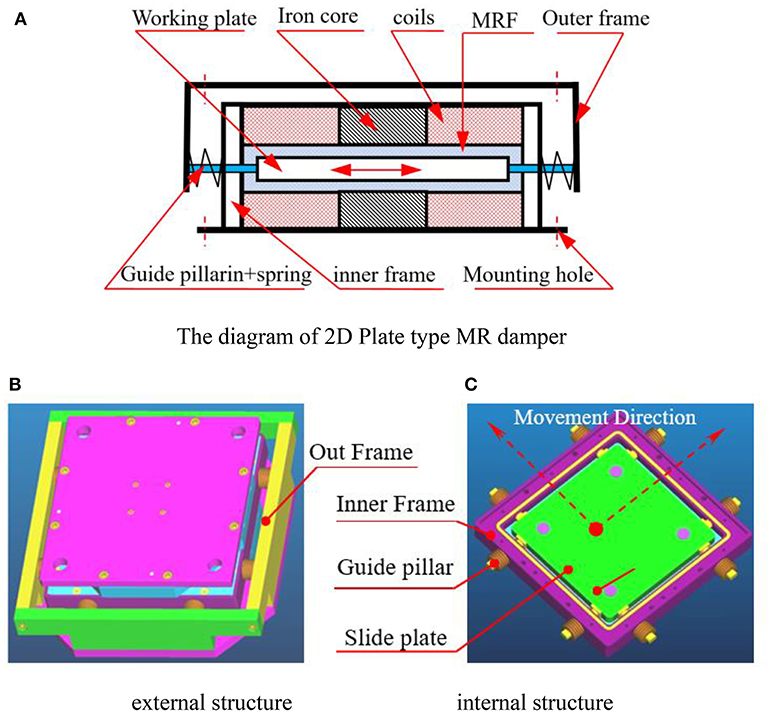
Figure 1. Structure of bipolar coil 2-D plate-type MRD. (A) The diagram of 2D Plate type MR damper. (B) External structure. (C) Internal structure.
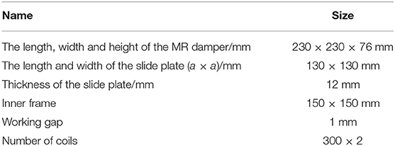
Table 1. The main size of the damper.
The relative motion among the components of the 2D plate type MR damper is complicated. When the outer frame drives the guide pillars, the outer frame slides perpendicular to the axis, relatively to pillars at the same time. In the same way, the pillars drive the slider to move, and the slider slides relatively to the pillars. The wide of interval between the slider and the surface of the cavity depends on the height of the copper pillar embedded in the slider.
Structural Design for Magnetic Circuit
The structure of the magnetic circuit of the 2D plate MR damper is shown in Figure 2. The magnetic circuit is composed of two coils with iron cores in the center. By means of controlling the winding direction of the coil, the superimposed magnetic field can be obtained at the working gap of the damper. The dash line in the picture is the magnetic field lines produced by the magnetic flux pass through the iron core.
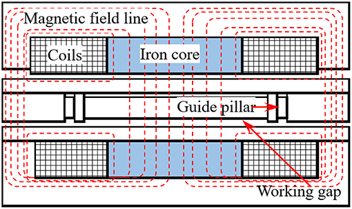
Figure 2. Diagram of bipolar magnetic circuit structure.
Modeling for MR Damper
Equation of Motion
The MR effect of MRFs is a typical characteristic for the MR damper and it appears when the MRFs are exposed to an external magnetic field. Since the carbonyl iron particles inside the MRFs form chains and clusters along the direction of the external magnetic field, the relative direction of the flow and the external magnetic field would affect the MR effect largely (Gong et al., 2014). Therefore, the rheological characteristics of the MRFs depended on the direction of the flow relative to the external magnetic field. The behavior of the MRFs can be divided into three categories according to the relative direction of the flow and the external magnetic field: flow mode, shear mode, extrusion mode (Liao et al., 2002), and any combination of these three basic modes. Based on the structural characteristics of the damper in this paper, the work mode of the MRFs is the composite mode of flow and shear mode. The flow model coordinates are established as shown in Figure 3. The MRFs are regarded as generalized Newtonian fluids. The symbol u is the motion velocity of slide plate, the symbol δ is the working unilateral clearance of the plate, and ηα is the apparent viscosity of MRF. According to the Navier-Stokes equation, the equation of motion of MRF can be obtained, i.e.,
In Equation (1), ρ, , p and mean density, mass force, pressure, and velocity of MR fluids, respectively, and then .
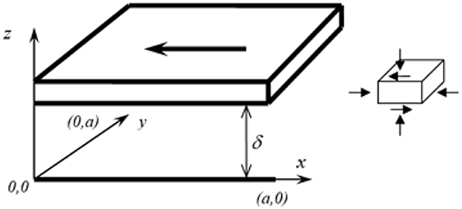
Figure 3. Coordinate model of the flowing MRF between a gap.
The following assumptions are made: The flow of MR fluids is laminar and non-slip between plates, that is, the velocity of the fluid is the same as that on the plate. Mass forces, such as gravity, are negligible and MRFs are incompressible. That is: ρ = const. The pressure is constant along the z direction, namely, .
The motion is stable, namely, .
According to the rheological effect of MRFs, the relationship between shear stress τ and shear rate is a power law, and the apparent viscosity ηα (m2s−1) is only related to the magnetic field strength H and (Wang et al., 2016), i.e., and ).
Based on the structure of 2D MR plate type damper, the thickness value of slide plate (z direction) is much smaller than that of slide length (x direction) and width (y direction), so uz can be neglected, and then:
The movement of intermediate slide plate is active, according to the knowledge of fluid mechanics, and the boundary conditions of MRFs can be established for two-dimensional motion.
where ux0 and uy0 are the initial velocities in x and y directions. The two-dimensional components of velocity can then be obtained.
Pressure Components Under Two-Dimensional Vibration
Because the motion equation is linear, the pressure p (x, y) can be regarded as a linear combination in two directions:
When vibration is produced in the x and y directions, the following boundary conditions are discussed:
In Equation (5), the dimensionless quantity kp represents the upstream pressure ratio of y direction and x direction. Boundary conditions for two components of pressure can be written as follows:
where a is the length of the intermediate slide plate. Combining the method of separation of variables and the fluid continuity equation, the two-component equation of pressure can be obtained as follows:
Therefore, the pressure distribution model under two-dimensional vibration can be expressed as:
The MRF pressure distribution of the vibration in two directions is simulated and shown in Figure 4. It can be found that when kp = 1, the value of p (x, y) is coordinate symmetric, and obtains the largest at the initial position, while the distribution of p (x, y) shows inhomogeneity when kp = 0.5.
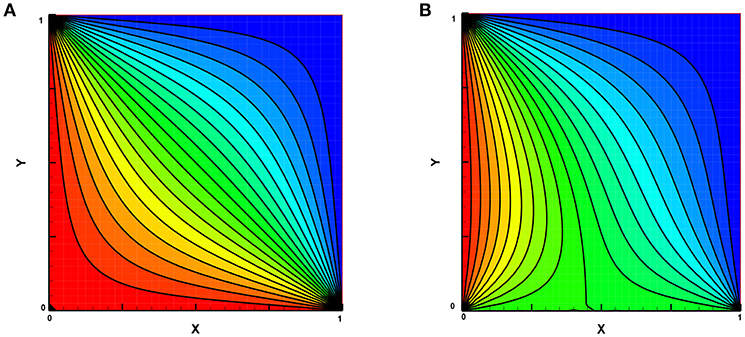
Figure 4. MRF pressure distribution in two directions. (A) Pressure distribution line(kp = 1). (B) Pressure distribution line (kp = 0.5).
Velocity and Flow Distribution
Combined with the structural characteristics of the damper, the two-dimensional velocity component Equation (3), and the damper pressure distribution Equation (9), we can establish the velocity distribution model of the absorber in the x, y directions:
Due to the symmetry of the working clearance of the MR fluids of 2D plate type damper, only one side flow calculation model is established to calculate the flow rate. Under two dimensional vibrations, the flow rate can be expressed as the flow rate Qs1_x and Qs2_y at one side clearance at x0 and y0. The fluid motion equation can be obtained as follows:
According to the continuity principle of hydrodynamics, the squeezed flow generated by plate movement ux0·a·hb should be equal to that of MRF flow from two pairs of parallel plates. And then:
From Equation (12), we can obtain:
Thus, according Equation (13), kp can be calculated by the following formula:
By substituting Equation (12) into (10), p can be obtained.
Damping Force Calculation
According to the structural characteristics of shock absorber, the working mode of MR fluids is mixing mode of shear and flow. Therefore, in mechanical modeling, only shear force and damping force formed by differential pressure flow are considered in this paper. The shear damping force Fxs, Fys in the direction of x, y can be obtained by combining Equations (10), (11), and (12). That is:
The damping force produced by the pressure difference in the direction of x, y can be approximately expressed as:
Therefore, the damping force Fx, Fy produced by shear and pressure can be calculated as follows:
The kp and p in Equations (15) ~ (17) are determined by Equation (14) and Equation (12). Regardless of the direction, we can see from Equation (17) that the damping force is correlated with the apparent viscosity ηα of MRFs, the vibration velocity ux0 and the area of the working surface of the 2-D plate type MR damper. The damping force increases with a decrease of the clearance δ of the damper, and/or increase in the intermediate plate's thickness hb.
The theoretical analysis indicates that the apparent viscosity ηa is a function of zero field dynamic viscosity η0, the applied magnetic field strength H and shear strain. It is generally considered that the apparent viscosity consists of zero field viscosity and magnetic viscosity. The value of magnetic viscosity is several to dozens of times bigger than that of zero field viscosity under the effect of hysteresis. Therefore, two damping characteristics are presented in the damping force of MR damper i.e., viscous damping and Coulomb damping. Viscous damping is determined by the zero magnetic field dynamic viscosity of the MRFs and the structure size of MR damper, independent of the external magnetic field. However, the Coulomb damping is dependent on the external magnetic field, the material properties of MRFs, the relative motion velocity and the structure size. In general, the value of Coulomb damping force is much bigger than that of the large viscous damping force. For 2-D plate type damper, the main geometric factors affecting the damping force are the thickness hb of the intermediate slide, the length a of the intermediate slide, and the clearance δ between the two parallel plates.
Test Bench and Experiment Principle
The basic structure of the MR vibration test system is shown in Figure 5. The main function of the base is to support and fix the part of the support frame. And the inner part of the frame, mainly composed of converter motor and eccentric mechanisms, is an exciting part to start or stimulate the vibration. The MR dampers are used to connect the exciting part and the support frame. Through adjusting the meshing position of the gears, the mass centers of two eccentric wheels form a certain angle with respect to their axes, as shown in Figure 6. When the angle is 90°, the amplitudes in both longitudinal and transverse directions are the maximum. In this paper, we only discuss the damping effect of the MR damper under the two-dimensional excited vibrations.
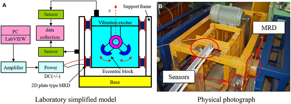
Figure 5. The experimental instrument. (A) Laboratory simplified model. (B) Physical photograph.
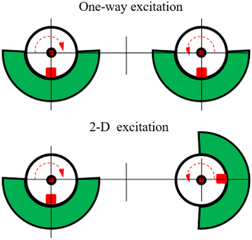
Figure 6. Eccentric block position in 2-D coupled vibration.
A photo of 2-D plate type MR damper is shown in Figure 7. The experiment process, as illustrated in Figure 5A is described as follows: the vibration bench displacement signal and acceleration signal, after denoising, are collected into the computer through the data acquisition card. It is analyzed, processed and displayed on the platform based on LabVIEW virtual instrument control, and the vibration velocity and displacement amplitude are obtained. The vibration absorption performance is further analyzed and studied by sampling data.
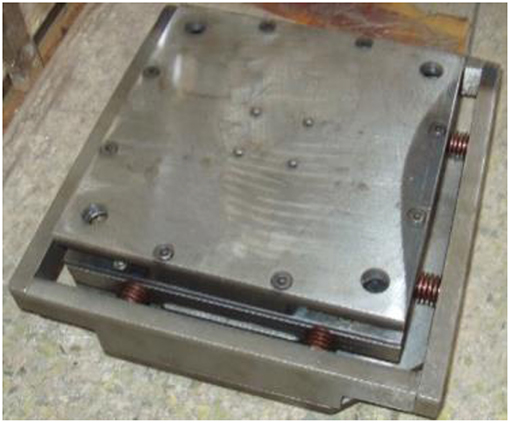
Figure 7. Photo of the 2-D plate-type MRD.
In the experiments, the eddy current displacement sensor, combined with the high-speed data acquisition card PCI-MIO-16E-1, is used for the data acquisition. Signals gathered are sent to dynamic signal analyzer NI-4552 for processing. The whole data acquisition system is under the management of programs developed by the software platform LabVIEW. The A/D converter has 12 bits. It is written by G language given by software LabVIEW and executed with a data sampling frequency of 1,000 Hz and reading frequency of 500 Hz according to the Nyquist sampling theorem.
Experimental Analysis of 2-D Plate Type MRD
The type of MRF we chose in the experiment is MRF2035 shown in Figure 8. The MRF is mainly composed of non-magnetic liquid-dimethicone and fine soft magnetic particles with high magnetic permeability and low hysteresis uniformly dispersed therein. The high yield strength of the MRF can reach 55 kPa.
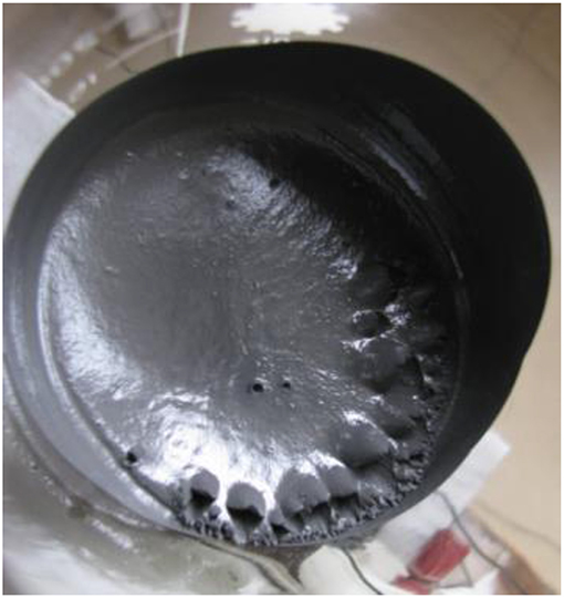
Figure 8. The MRF.
A variety of testing conditions are realized by adjusting the frequency converter for different motor rotations. The range of the exciting frequency f is 8 ~ 32 Hz, and the control current applied on the excitation coils of the MR damper are 0, 0.5, 1.0, 1.5, and 2.0 A. The amplitude responses of longitudinal and transverse vibrations of MR damper are obtained, as shown in Figure 9.
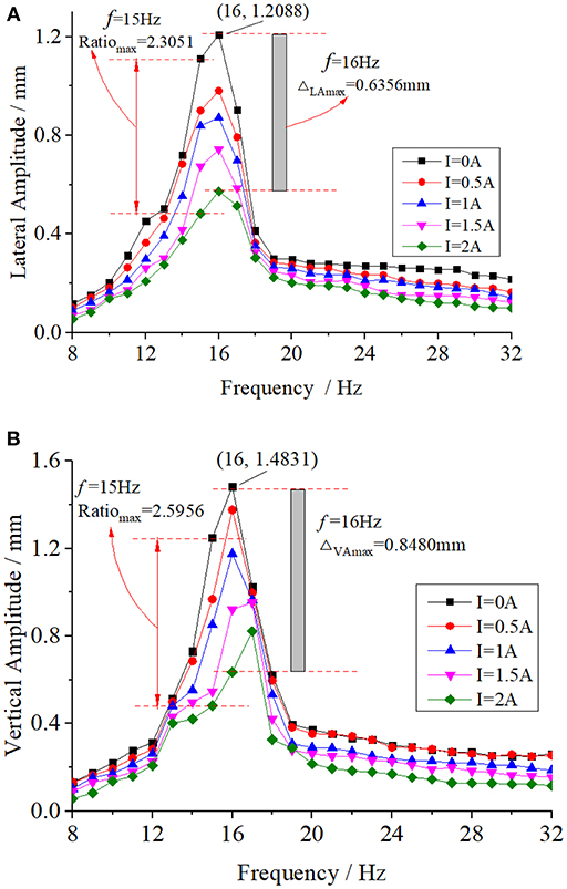
Figure 9. Lateral and vertical amplitude at different excitation frequencies. (A) Transverse amplitude. (B) Longitudinal amplitude.
From Figure 9, it can be seen that when the input current I on the excitation coil is 0 A, i.e., the zero sum of the viscous damping force of the damper and the restoring force of the spring, the amplitude of the vibration system is the largest at each frequency. When the input current I of the excitation coil gradually increases to 2 A, the amplitude of the system decreases gradually. For example, when f = 14 Hz, the transverse amplitudes of the system are 0.7218, 0.6839, 0.5537, 0.168, and 0.3755mm at the excitation current I of 0, 0.5, 1, 1.5, and 2 A, respectively. The longitudinal amplitudes were 0.7305, 0.6856, 0.5532, 0.4974, and 0.4208 mm. When f = 16 Hz, the transverse and longitudinal amplitudes of the excitation system reached their maximum values, 1.2088 and 1.4831 mm, respectively. When the frequency was higher than 16 Hz, the amplitude decreased gradually. In addition, it is found that the transverse amplitude is slightly smaller than the longitudinal, which is related to the inherent characteristics of the simulator. The resonance frequency of the system is 16 Hz, when the amplitude obtains the largest. The amplitude decreases gradually as the frequency increases with unit time. The excitation component has its own gravity, and the longitudinal amplitude is slightly larger when combined with the eccentric wheel.
In the experimental frequency range, with an increase of the current I in the excitation coil, the amplitude decreases, indicating that the damping force increases with increase of the current. When I = 2 A, the maximum decrease in amplitude is observed at f = 16 Hz. The decrease of transverse amplitude is 0.6356, and 0.8480 mm for the longitudinal. After calculation, the results show that the shear rate of shock absorber reaches the maximum when f = 16 Hz, suggesting that the output of damping force is greatly influenced by large shear rate.
Table 2 shows the ratios of amplitudes (transverse ratio RatioLA and longitudinal ratio RatioVA) at different excitation frequencies f between I = 0 A and I = 2 A. Combined with Figure 9, it is found that the ratio of amplitude is >1 between I = 0 A and I = 2 A, meaning that the damping force plays an important role in suppressing the vibration when the excitation current is applied, and in the case of f = 15 Hz not at f = 16 Hz, the transverse and longitudinal amplitude ratio showed the maximum values of: 2.5956 and 2.3051, respectively. This is due to the smaller ratio of exciting force of exciter at f = 15 Hz and little difference of shear rate between two frequencies.
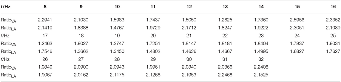
Table 2. Different excitation frequency f, lateral amplitude (LA) ratio and vertical amplitude (VA) ratio (I = 0 A's amplitude, I = 2 A's amplitude).
Conclusion
In this work, the structure of 2D plate type MR damper is designed. The velocity distribution, pressure distribution, flow model, and damping force have been established based on MRFs under bidirectional vibration conditions. The vibration absorption effect of dampers is tested on a two-dimensional exciting test bench. Based on the results, the following conclusions can be drawn:
(1) The damping force of 2D plate type MR damper is related to the clearance between parallel plates, the length and thickness of the intermediate slider, the zero magnetic field dynamic viscosity of MR fluid, and the working magnetic field intensity.
(2) The proposed 2-D plate type MR damper has good damping performance. The damping force increases with an increase of the control current. The larger the shear rate, the more obvious the damping effect. The maximum damping ratio of amplitude can reach up to 2.5956.
Author Contributions
BC desiged the plate-type MRD, and DH and CL did the experiments. CC helped with the writing of the article.
Conflict of Interest Statement
The authors declare that the research was conducted in the absence of any commercial or financial relationships that could be construed as a potential conflict of interest.
Acknowledgments
This work was supported by National Natural Science Foundation of China (No. 51305079), Natural Science Foundation of Fujian Province (No. 2015J01180), and outstanding young talent support program of Fujian Provincial Education Department (No. JA14208, JA14216). These financial supports are gratefully acknowledged.
References
Anwesa, B., and Manas, D. (2018). Nano-finishing of bio-titanium alloy to generate different surface morphologies by changing magnetorheological polishing fluid compositions. Prec. Eng. 51, 145–152. doi: 10.1016/j.precisioneng.2017.08.003
Cha, Y. J., Agrawal, A. K., Phillips, B. M., and Spencer, B. F. Jr. (2014). Direct performance-based design with 200 kN MR dampers using multi-objective cost effective optimization for steel MRFs. Eng. Struct. 71, 60–72. doi: 10.1016/j.engstruct.2014.04.023
Chen, B. S., and Huang, Y. J. (2009). Analysis of non-linear characteristics of a magnetorheological damping system. China Mech. Eng. 20, 2795–2799.
Christie, M. D., Sun, S., Deng, L., Ning, D. H., Du, H., Zhang, S. W., et al. (2019). A variable resonance magnetorheological-fluid-based pendulum tuned mass damper for seismic vibration suppression. Mech. Syst. Signal Process. 116, 530–544. doi: 10.1016/j.ymssp.2018.07.007
David, A. C., Behzad, T., and Edmond, R. (2014). Dynamical modeling and experimental study of a small-scale magnetorheological damper. IEEE/ASME Trans. Mechatr. 19, 1015–1024. doi: 10.1109/TMECH.2013.2265701
Edward, J. P., Falcãoda, L., and Afzal, S. (2008). Multidisciplinary design optimization of an automotive magnetorheological brake design. Comput. Struct. 86, 207–216. doi: 10.1016/j.compstruc.2007.01.035
Gong, X. L., Ruan, X. H., Xuan, S. H., Yan, H., Deng, H., et al. (2014). Magnetorheological damper working in squeeze mode. Adv. Mech. Eng. 2014, 1–10. doi: 10.1155/2014/410158
Ha, Q., Royel, S., and Balaguer, C. (2018). Low-energy structures embedded with smart dampers. Energy Build. 177, 375–384. doi: 10.1016/j.enbuild.2018.08.016
Hema, L. K., Sri, U. P., and Seetharamaiah, N. (2017). Design and manufacturing aspects of magneto-rheological fluid (MRF) clutch. Mater. Today 4, 1525–1534. doi: 10.1016/j.matpr.2017.01.175
Jang, K. I., Jongwon, S., Min, B. K., and Lee, S. J. (2010). An electrochemomechanical polishing process using magnetorheological fluid. Int. J. Machine Tools Manufact. 50, 869–881. doi: 10.1016/j.ijmachtools.2010.06.004
Kang, S.-R., Cha, S.-W., Hwang, Y.-H., Lee, Y. S., Choi, S. B., et al. (2018). Controllable magnetorheological fluid based actuators for 6-degree-of-freedom haptic master applicable to robot-assisted surgery. Sensors Actuators A 279, 649–662. doi: 10.1016/j.sna.2018.06.057
Liao, C. R., Yu, M., Chen, W. M., Liang, X. C., and Huang, S. L. (2002). Issues in design rules of a magnetorheological fluid shock absorber for automobile. China Mech. Eng. 13, 723–726.
Luo, H., Guo, M. J., Yin, S. H., Chen, F., Huang, S., Lu, A., et al. (2018). An atomic-scale and high efficiency finishing method of zirconia ceramics by using magnetorheological finishing. Appl. Surf. Sci. 444, 569–577. doi: 10.1016/j.apsusc.2018.03.091
Luu, M., Martinez-Rodrigo, M. D., Zabel, V., and Könke, C. (2014). Semi-active magnetorheological dampers for reducing response of high-speed railway bridges. Control Eng. Pract. 32, 147–160. doi: 10.1016/j.conengprac.2014.08.006
Mohammad, M. Z., and Amir, M. H. (2018). Supervisory adaptive non-linear control for seismic alleviation of inelastic asymmetric buildings equipped with MR dampers. Eng. Struct. 176, 849–858. doi: 10.1016/j.engstruct.2018.09.045
Nguyen, P.-B., Do, X.-P., Choi, S. B., Jeon, J., Liu, Y. D., and Choi, H. J. (2014). Brake performance of core–shell structured carbonyl iron/silica based magnetorheological suspension. J. Magn. Magn. Mater. 367, 69–74. doi: 10.1016/j.jmmm.2014.04.061
Pang, H., Liu, F., and Xu, Z. R. (2018). Variable universe fuzzy control for vehicle semi-active suspension system with MR damper combining fuzzy neural network and particle swarm optimization. Neurocomputing 306, 130–140. doi: 10.1016/j.neucom.2018.04.055
Shaju, J., Anirban, C., and Norman, M. W. (2008). A magnetorheological actuation system: test and model. Smart Mater. Struct. 17:025023. doi: 10.1088/0964-1726/17/2/025023/meta
Shiao, Y. J., and Nguyen, Q. A. (2014). Torque enhancement for a new magnetorheological brake. Proced. Eng. 76, 12–23. doi: 10.1016/j.proeng.2013.10.001
Topcu, O., Yigit, T., and Konukseven, E. I. (2018). Design and multi-physics optimization of rotary MRF brakes. Results Phys. 8, 805–818. doi: 10.1016/j.rinp.2018.01.007
Wang, H. T. (2010). Model and analysis of damping for twin-tube magneto-rheological fluid damper based on disc type orifice. J. Mech. Eng. 46, 139–144.
Wang, S. Q., Li, D. C., and Ju, B. X. (2016). Preparation and properties of a magnetorheological fluid with oleic acid-coated magnetic particles. Function Mater.7, 7153–7156. doi: 10.3969/j.issn.1001-9731.2016.07.029
Yang, G., Spencer, B. F., Jung, H. J., and Carlson, J. D. (2002). Phenomenological model of large-scale MR damper systems. Adv. Build. Technol. 1, 545–552. doi: 10.1016/B978-008044100-9/50070-X
Yu, J. Q., Dong, X. M., and Zhang, Z. L. (2017). Design and control of automobile novel magnetorheological shock absorber with asymmetric mechchenics properties. China Mech. Eng. 28, 372–377. doi: 10.3969/j.issn.1004-132X.2017.03.020
Zhang, J. Q., Peng, Z. Z., Zhang, J., and Jie, Y. (2013). Dynamic analysis on vibration absorber of PVDF grain detecting sensor. J. Vib. Measurement Diagn. 33, 132–137. doi: 10.16450/j.cnki.issn.1004-6801.2013.01.013
Keywords: magnetorheological fluids, two-dimensional plate-type magnetorheological damper, mechanical modeling, damping experiments, plate-type
Citation: Chen B, Huang D, Li C and Chen C (2019) Design and Modeling for 2D Plate Type MR Damper. Front. Mater. 6:28. doi: 10.3389/fmats.2019.00028
Received: 03 December 2018; Accepted: 11 February 2019;
Published: 05 March 2019.
Edited by:
Seung-Bok Choi, Inha University, South KoreaReviewed by:
Taihong Cheng, Wenzhou University, ChinaJung Woo Sohn, Kumoh National Institute of Technology, South Korea
Copyright © 2019 Chen, Huang, Li and Chen. This is an open-access article distributed under the terms of the Creative Commons Attribution License (CC BY). The use, distribution or reproduction in other forums is permitted, provided the original author(s) and the copyright owner(s) are credited and that the original publication in this journal is cited, in accordance with accepted academic practice. No use, distribution or reproduction is permitted which does not comply with these terms.
*Correspondence: Bingsan Chen, YnNjaGVuMTI2QDE2My5jb20=