 Artur Olszak1
 Karol Osowski2Przemysław Motyl2Grzegorz Mędrek2Jan Zwolak3Andrzej Kęsy2Zbigniew Kęsy2
 Seung-Bok Choi4*
- 1Technical Department, New Chemical Syntheses Institute, Puławy, Poland
- 2Faculty of Mechanical Engineering, Institute of Applied Mechanics and Energetics, Kazimierz Pulaski University of Technology and Humanities, Radom, Poland
- 3Department of Mechanics and Mechanical Engineering, University of Rzeszów, Rzeszów, Poland
- 4Inha University, Incheon, South Korea
This article presents considerations regarding materials used to fabricate a hydraulic clutch with an ER fluid operating in non-standard working conditions. The hydraulic clutch was a subassembly of the device used for exerting a controlled force on the stationary object. This clutch was driven by an electric motor. The force was controlled by changing the shear stresses in the ER fluid. Shear stresses were changed in two ways: by changing the angular velocity of the electric motor and by changing the high voltage applied to the electrodes located on the driving part and the driven part of the clutch. The increase in these stresses caused an increase in the torque transmitted and an increase in the pressure force. In order to construct the clutch, mathematical models based on the Bingham model were developed, which took into account the influence of temperature and humidity on the shear stress in the ER fluid, allowing calculation of the clutch performance. In addition, numerical calculations of the temperature distribution inside the clutch were carried out using the ANSYS program because of the intense heat generation during the clutch operation. The developed mathematical models were used to optimize the clutch. The aim of the optimization was to obtain a high transmitted torque with small dimensions of the clutch, taking into account the thermal capacity of the clutch. Based on the optimization results, a prototype of a hydraulic clutch with an ER fluid was designed and made, assuming that for metal materials their anti-corrosion properties are the most important, since the presence of conductive metal oxides causes electrical breakdowns. The plastics used in the clutch prototype were mainly evaluated for insulating properties and high temperature resistance. When choosing the ER fluid, its sensitivity to temperature and humidity as well as durability were taken into account. The clutch prototype has been tested on a specially built test rig. The test results confirmed the proper selection of both construction materials and ER fluids. Based on the results of these tests, guidelines for the construction of clutches with ER fluids were formulated.
Introduction
The most important factors that have recently contributed to mechanical devices' better results and which have increased the devices' reliability are the implementation of new materials and integration with digital electronics. In viscous clutches and brakes, both of these factors are combined by using new construction materials and hydraulic working fluids of a new type, i.e., smart fluids which react to a physical field by altering their rheological properties.
Two types of smart fluids are in use: electrorheological fluids (ER) and magnetorheological fluids (MR), activated, respectively with an electrical or magnetic field. ER and MR fluids are divided into two groups, according to their composition: monophasic and biphasic. Monophasic fluids are homogeneous while biphasic fluids consist of two phases: solid and liquid.
Viscous clutches consist of the driving part connected to input shaft and the driven part connected to the output shaft. Immobilizing the driven part causes the clutch to become a brake. In these clutches the torque is transmitted as a result of friction caused by shear stress in the working fluid between the driving part and the driven part. Two main types of viscous clutches can be distinguished, according to the shape of driving and driven part: cylindrical and disc clutches.
Due to the necessity to create an electric or magnetic field in the gap containing working fluid, building clutches and brakes with smart fluids proves much more complex than building clutches and brakes with typical working fluids. In viscous clutches with ER fluids, the electric field is usually created between two electrodes, one of which is situated in the driving part and the other in the driven part of the clutch. In such clutches, in order to convey the voltage to electrodes connected with the movable part of the clutches, additional electrical wires and sliding rings are used. However, in the viscous clutches with MR fluid, electromagnet cores and coils must be installed in addition to electrical wires and sliding rings. Due to these reasons, viscous clutches with MR fluids weigh more, and there is consequently more inertia of the rotating parts, which is unfavorable for the control of the clutches. The complicated structure of the clutches and brakes with smart fluids makes it necessary to select materials with proper properties as well as to choose design methods based on mathematical modeling and numerical calculations.
So far, to control the torque, a vital feature of viscous clutches and brakes was used: the dependence of torque on angular velocity of the input shaft. Altering the angular velocity enables the control of the transmitted torque. The torque can also be controlled by changing temperature, pressure or volume of the working fluid within the clutch. For viscous clutches and brakes built with new materials such as smart fluids, the control is achieved by causing changes in shear stress, influencing the ER or MR fluid with an appropriate field with regulated voltage. The change in electric or magnetic field is achieved by changing voltage or current with electronically controlled electric power supplies. Increase in shear stress within the working fluid causes increase in the torque transmitted by viscous clutches or brakes.
The paper presents the results of design optimization and experimental research of a viscous disc clutch with an ER fluid, working in unusual thermal conditions. The aim of the design optimization was to achieve a large torque of the clutch, with a small size of the clutch, and at the same time a small area of heat dissipation. However, the working fluid temperature of the clutch was kept close to the temperature of the surroundings. The multi-objective optimization was carried out based on mathematical models of the ER fluids and a disc viscous clutch. The multi-objective optimization of the viscous clutch with the ER fluid including the quality of materials had not been conducted in this way before. Subsequently, a prototype of a viscous clutch with the ER fluid was made and tested on a specially built test rig. The obtained results allowed the compilation of principles for constructing viscous clutches with ER fluid, including choice of materials.
Literature Study
In the practically used biphasic ER and MR fluids, the solid phase is comprised of particles of polymer or iron, respectively, of diameter ranging from 5 to 10 μm, and the liquid phase—silicon oil (Fertman, 1990; Conrad, 1993; Weiss, 1993; Mikkelsen et al., 2017). The biphasic fluids also contain additives (up to 3%) that prevent sedimentation and aggregation of the solid phase and increase the electrorheological or magnetorheological effect. A percentage of contents of the solid phase in biphasic ER and MR fluids is, according to weight, 60–80% and according to volume, 20–30%. One limitation in the use of the ER fluid is its sensitivity to temperature changes and air humidity. MR fluid use is limited by the magnetic saturation phenomenon.
ER and MR fluids are used or predicted to use mainly as materials with controlled rheological properties in a variety of devices, such as haptic devices (Liu et al., 2006), energy absorbers (Milecki et al., 2005; Choi and Wereley, 2015), dampers (Sapiński et al., 2016), cantilever beams (Lara-Prieto et al., 2010), hydrodynamic clutches (Madeja et al., 2011; Olszak et al., 2018), discharge machines (Kim et al., 2002), or even robots (Saito and Ikeda, 2007; Jing et al., 2018) and seismic isolators (Li et al., 2013).
The most frequent uses of ER and MR fluids are in devices such as clutches and brakes (Olszak et al., 2016a; Raju et al., 2016; Gao et al., 2017). To achieve the assumed characteristics of clutches and brakes with ER and MR fluids, their architectures are taken into consideration by analyzing the shape and position of working space (Avraam et al., 2010), the way of producing the electric or magnetic field (Takesue et al., 2003; Böse et al., 2013; Sohn et al., 2018) as well as thermal working conditions (Chen et al., 2015; Song et al., 2018). Additionally taken into consideration are the smart fluids used for construction of clutches and brakes with ER and MR, mainly their composition (Sarkar and Hirani, 2013; Kumbhar et al., 2015; Mangal et al., 2016) and durability (Olszak et al., 2016b; Kim et al., 2017; Ziabska et al., 2017). Examples of design solutions for clutches and brakes with smart fluids can be found in publications (Papadopoulos, 1998; Kavlicoglu et al., 2002; Smith et al., 2007; Fernández and Chang, 2016).
The next vital step on the way to improving the construction of clutches and brakes with smart fluids is using the optimization methods. In the publications concerning this subject, the geometric dimensions are optimized while the authors assume different objective functions and different optimization methods.
The optimization objects are usually devices with the MR fluid, used in vehicles. In previous works (Park et al., 2006, 2008) the construction process involved multidisciplinary design optimization; the objective function takes into consideration brake weight as well-braking torque and uses scalar weighting factors. In these works the assumption was that in a car, the brake weight is more important than braking torque. To decrease calculation time, three optimization methods were used, the first two being less effective: built-in capabilities of ANSYS and then a random-search method, which gave the lowest objective function values. During the optimization, CFD analysis was also conducted and magnetic field intensity distribution along with steady-state temperature distribution were evaluated. Nguyen and Choi (2010), in the process of a car brake optimization and while defining the objective function, took into consideration the following aspects: required braking torque, temperature due to zero-field friction of MR fluid, mass of the brake system and geometric dimensions. The optimization method used there was based on finite element analysis. In the work (Assadsangabi et al., 2011), the objective function was assumed in a way which allowed the largest possible braking torque with the smallest possible weight of the car brake. The optimization was conducted with the use of finite element analysis and Genetic Algorithm. The aim of the work (Sohn et al., 2015) was the optimization of a motorcycle brake. In the objective function, factors taken into consideration were braking torque, weight and temperature. In the optimization process a tool based on finite element analysis was used. In research (Nguyen and Choi, 2010) concerning a passenger vehicle magnetorheological damper, the objective function included damping force, dynamic range and inductive time constant of the damper. In the optimization method based on finite element analysis, a golden-section analysis algorithm and a local quadratic fitting technique were used.
Dimension optimization of the clutches with MR fluid can be found in two previous articles (Horvath and Torőcsik, 2011; Bucchi et al., 2017). In both, the optimization was aimed to achieve the largest possible transmitted torque of the clutch, while in Bucchi et al. (2017) emphasis was put on the magnetorheological fluid gap shape, and the optimization was conducted while using the finite element method. However, in Horvath and Torőcsik (2011) the inner radius was emphasized, while the optimization was based on the simple analytical method and a simulation procedure. The article (Gao et al., 2017) depicts the optimization of a MR damper designed for smart prosthetic knees. In the objective function, factors taken into consideration were total energy consumption during one gait cycle and weight of the MR damper. The optimization was conducted based on the particle swarm optimization algorithm. The original optimization method called the Taguchi Method was used to optimize the magnetorheological brake actuator (Erol and Gurocak, 2011). In the objective function, torque-to-volume ratio was taken into consideration.
Mathematical Model
While defining the mathematical model of the ER fluid, it was assumed that rheological properties of the fluid can be described by the Bingham model:
while for U = 0, , and the electric properties of the ER fluid can be described with the equation:
where μp is plastic viscosity, τ0 is electric field-dependent yield stress of ER fluid, μ0 is the ratio of dynamic viscosity of fluid without an electric field, and ig is the density of current leakage.
The relation of τ0, μ0, ig to electric field E was described by formulas, in which temperature T, relative air humidity w and shear rate were taken into consideration:
where a0, b0, c0, a2, b2 are numerical coefficients; a1, b1, c1 are coefficients depending linearly on temperature T; a3, c2 is coefficients depending linearly on relative air humidity w; and c3 is coefficients depending linearly on shear rate .
It was assumed that radiuses r in the mathematical model of the viscous clutch with ER fluid are described by a proportional enlargement of the model clutch whose geometry was determined based on the analysis of already existing clutches and brakes with smart fluid (Papadopoulos, 1998; Kavlicoglu et al., 2002; Smith et al., 2007; Nguyen and Choi, 2010; Erol and Gurocak, 2011) using the magnification factor sk. The width of the model clutch is calculated depending on the number of discs n with a constant width of the gap h between discs. Figure 1 shows a construction scheme of a model viscous clutch with ER fluid, and Table 1 shows juxtaposed dimensions of the clutch, dependent on magnification factor sk and number of working gaps n.
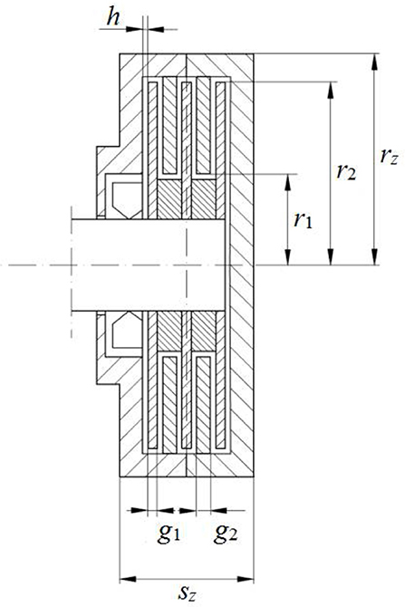
Figure 1. Construction scheme of a model viscous clutch with ER fluid with 5 discs.
Table 1. Dimensions of the clutch with ER fluid assumed for optimization.
During the optimization process of the clutch, the following calculations were made: torque transmitted through the clutch M, the clutch's power P, the clutch's volume O, temperature of the ER fluid in clutch TZ, and centripetal acceleration ad. Calculations were made based on the following formulas:
where T is the temperature of the surroundings and is the surface of the electrode's side.
The torque M transmitted through the viscous clutch with the ER fluid was calculated by integration of unit force occurring on the radius r, with the simplifying assumption that the shear stress τ does not change—neither along the disc radius nor along the gap height. The result was the following equation:
where, subsequently, the formula (1) (Park et al., 2008; Erol and Gurocak, 2011) was taken into consideration.
The temperature TZ was calculated from an equation describing heat Θ released into the surroundings in the moment Δt assuming that the clutch works with a constant power P in set conditions:
where α -is the heat transfer coefficient and T is the temperature of the surroundings.
The quantities described by formulas (4) are construction indicators of the viscous clutch with ER fluids, depicting its characteristic features, such as performance (P, M), dimensions (O) and working conditions (T, TZ, ad).
Optimization of the Viscous Clutch With ER Fluid
The Way of Conducting the Optimization Calculations
The main goal of the optimization was to receive a viscous clutch with ER fluid with the smallest possible dimensions, transmitting the largest possible torque, but at the same time the amount of dissipated heat, dependent on the side surface of the clutch, ensured a possibly low temperature of the ER fluid during the constant work of the clutch.
Two objective functions were created, containing relations M/O and TZ/T. Relation M/O should be as large as possible to receive the largest possible torque M from a construction with the smallest possible volume O. However, the relation TZ/T should generate possibly small values to reduce temperature change, and consequently the temperature's influence on the ER fluid's attributes. The assumed limitations were the values of power P, centripetal acceleration ad and current ic.
The objective functions were as follows:
where: wi (i = 1, 2) is a weighting factor for the i th objective function.
Equation (8) was formulated based on the weighted sum method which is the most widely used method for multi-objective optimization. In this study it was assumed that and 0 ≤ wi ≤ 1. The coefficients w1 and w2 have no physical meanings.
The minimal values of these objective functions were needed:
- for allowed values from the scopes: l ≤ sk ≤ 8; 30 ≤ ω ≤ 250 rad/s; 5 ≤ n ≤ 13;
- with the constraints: P ≤ 1000 W; ad < 300 rad/s2; ic < 100 mA.
For optimization calculations, an individual computer program was used, written in Delphi programming language. The calculations were conducted as follows:
- a random number generator was used, allowed values were drawn from the assumed ranges of allowed values;
- a check was conducted to ensure that constraints were met;
- if the drawn values of the allowed values met the constraints' conditions, objective functions were calculated; if not, the allowed values were drawn again;
- the calculated objective function was memorized and calculations were repeated;
- the objective functions' values from the former and current calculations step were compared;
- the smaller value was selected, and simultaneously the values calculated for the smaller value of the objective function were saved.
Based on several sets of geometric dimensions of viscous clutches with ER fluids (the sets that were deemed best), virtual solid models of the clutches were built. These models were subsequently used to calculate the distribution of temperature in the clutch with the aid of the ANSYS Fluent program. While calculating the heat created in working gaps of the clutch, the power emitted during electric current flow P1 = U · ic was taken into consideration, as well as power P2 emitted as a result of shear stress τ occurrences. Due to different dimensions of the clutches obtained during the optimization process, power P = P1+P2 was referred to the volume V of the ER fluids within the working gaps.
The relation of the power turned into heat to a unit of the fluid's volume P2/V was calculated assuming that the power dP emitted in the fluid ring of dr thickness can be written as:
After complying with dV = 2πr dr h and the result is:
and after integrating both sides of the equation and transforming:
In order to render the ratio P2/V dependent on the radius r it is taken into consideration that and which gives the result:
Data for Optimization
It was assumed that in a viscous clutch with ER fluid, the ERF#6 fluid would be used. It consists of sulphonated styrene-divinylbenzene resin with sodium cation and silicon oil; its data is presented in Table 2 (Płocharski et al., 1997; Bocińska et al., 2002) according to the producer's information. The ERF#6 fluid was selected mainly for its durability.
Table 2. Basic information on ERF#6 fluid.
Coefficients a, b, and c of the ERF#6 fluid's mathematical model, described with formulas (3), were determined based on tests conducted by a measuring device. The device was built similarly to a cylindrical rheometer, but the cylinders' diameters were much larger. The basic element of the device was a viscous clutch built with mutually isolated cylinders, connected to electric poles of a high voltage power supply. One of the cylinders, with an inner radius of 122 mm, was set directly on a shaft of a vertically installed asynchronous motor controlled with a frequency converter which enabled a fluent regulation of angular velocity ω. However, the second cylinder, with an outer diameter of 120 mm and a height of 29 mm, was connected to a lever of length l = 140 mm, which pressed the strain gauge force sensor F. The gap between the cylinders was h = 1 mm. The temperature of the fluid T was measured with a resistive sensor placed on the wall of the non-rotating cylinder. The influence of relative air humidity on the rheological characteristics of the ERF#6 fluid was tested by placing a measuring device in a plastic tent in which a constantly increased humidity which kept increasing in accordance with the placement of vessels with steaming water. The building scheme of the measuring viscous clutch is presented in Figure 2.
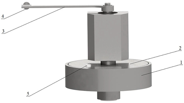
Figure 2. Scheme of the viscous clutch of the measurement device: 1, cylinder set on the motor's shaft; 2, cylinder connected to a lever; 3, lever; 4, force sensor; 5, temperature sensor output.
During the research, a computer measuring system registered the value of force F depending on the angular velocity ω and leakage current I for various values of electric voltage U applied to the cylinders. Next, the value of the force F was calculated into shear stress τ, and the angular velocity ω into shear rate according to the following equation:
where r2 is the radius of the cylinder connected to the lever, h is the size of the gap, M is torque, S = 2πr2b is shear area, l is the length of the force arm, and b is the height of the cylinder connected to the lever.
However, the electric field intensity was calculated basing on the formula:
The values of coefficients a, b, c of the ERF#6 fluid are juxtaposed in Table 3.
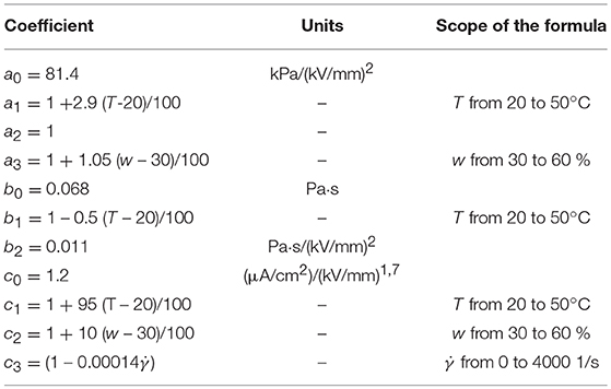
Table 3. Coefficients a, b, c appearing in mathematical model of ERF#6 fluid.
Value of the coefficient α, present in formulas (4) can be assumed from the scope 100 ÷ 150 W/(m2 K) (Nakamura et al., 2003). In the optimization calculations it was assumed that α = 120 W/(m2 K). The maximal value of the centripetal acceleration which can influence the ER fluid without causing degradation due to centrifugal force was assumed to equal 300 rad/s2 based on a previous publication (Carlson, 1997).
Optimization Results
Table 4 shows juxtaposed results of optimizing calculations of geometric dimensions of the viscous clutch with ER fluid. The results were obtained from minimization of the objective function described by the equation (7) for predefined chosen values of angular velocity ω.
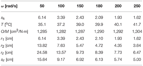
Table 4. Calculation results for T = 20°C, U = 2 kV, n = 12, w = 30%.
Table 5 shows the results of optimization calculations for the objective function described by equation (8) for different weighting factors w1, w2 chosen so that the magnification factor sk was close to 2. Referential values Tr = 37 oC, (O/M)r = 1290 cm3/Nm were assumed arbitrarily based on the results shown in Table 4.
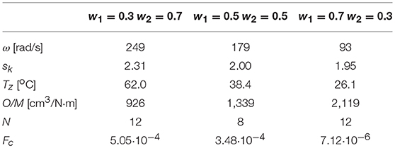
Table 5. Calculation results for U = 2 kV, 30 ≤ ω ≤ 250 rad/s, 5 ≤ n ≤ 13, w = 30%.
Figure 3 depicts the results of calculations for objective function described by formula (8) for different weighting factors, received as a result of 2,500 draws.
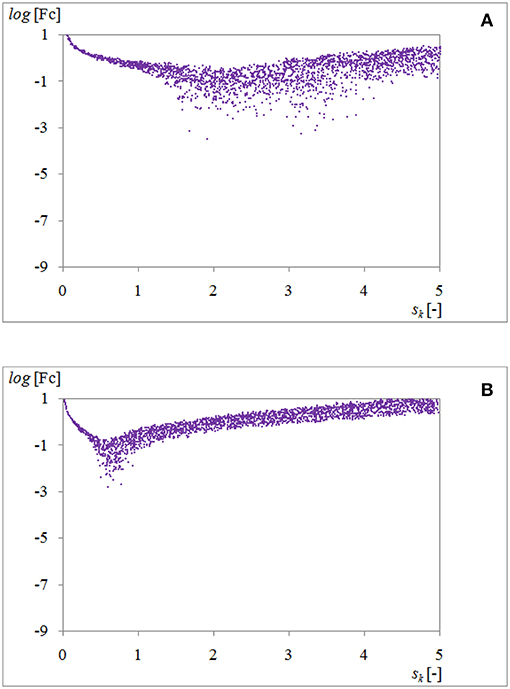
Figure 3. A set of values of the objective function described by the formula (8) for U = 2 kV, 30 ≤ ω ≤ 250 rad/s, 5 ≤ n ≤ 13, w = 30% and for: (A) w1 = 0.3, w2 = 0.7; (B) w1 = 0.7, w2 = 0.3.
Examples of diagrams showing dependence of P/V from radius r for angular velocity ω = 100 rad/s is shown in Figure 4.
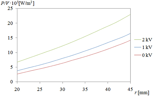
Figure 4. Dependence of P/V from radius r for ω = 100 rad/s and ERF#6 fluid.
Figure 5 shows the geometry of the clutch with ER fluid for sk = 2, while Figure 6. shows the calculated temperature distribution.
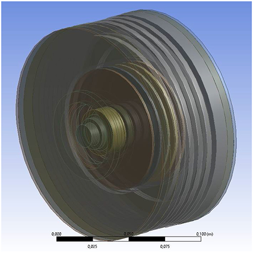
Figure 5. View of the clutch's geometry for sk = 2: brown color, discs; gray color, casing.
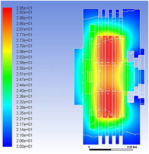
Figure 6. Temperature distribution in °C in the cross-section of the clutch for sk = 2, ω = 100 rad/s, U = 2 kV.
Discussion of the Results
As follows from the data in Table 4, for the objective function described with equation (7), for similar values of M/O ratio the increase of angular velocity ω of the driven part of the viscous clutch with ER fluid causes a decrease in the magnification factor sk and an increase in mass temperature T of the clutch. A clutch working at higher angular velocity ω transfers more power P, as shown in the equations (4). On the other hand, the lower value of the magnification factor sk means that the clutch has smaller dimensions and thus has smaller surfaces to dissipate heat, as can be seen from Table 1. Thus, the reason for the increase of the mass temperature T of the clutch with the increase of the angular velocity ω is the operation of the clutch at a higher power and a smaller area of heat dissipation.
By contrast, as follows from the data in Table 5, for similar values of the magnification factor sk (close to 2.0) the clutch works with the larger angular velocity ω, with the smaller weighting factor w1 determining the share of the temperature ratio TZ/Tr in the objective function described with equation (8), so wherein the smaller weighting factor w1 is, the higher the temperature TZ.
As shown in Figure 3, depicting the dependence of the objective function described by the equation (8) on the magnification factor sk, increasing the weighting factor w1 from 0.3 to 0.7 causes minimal values of objective function, and therefore optimal solutions exist for smaller values of magnification factor sk, that is for smaller dimensions of the clutch with ER fluid.
It results from the conducted research that the most important parameter while optimizing the clutch with ER fluid is power P emitted in the viscous clutch with ER fluid, which is dependent on two values: U and ω. The range of changes in the high voltage U for all clutches with ER fluids is similar and in practice does not exceed values from 0 kV to 3 kV, mainly due to the possible occurrences of electric breakdowns between electrodes which generate electric field. Thus, selection of optimal dimensions of a viscous clutch with ER fluids should be preceded by selecting the value of angular velocity ω.
It was assumed that the clutch with ER fluid in a constructed device which serves to exert controlled force will usually be working in the velocity ω range from 100 rad/s to 180 rad/s. For such a range ω based on the results from the conducted calculations, mainly the results presented in Tables 4, 5, and Figure 3, sk = 2 was assumed.
In order to verify the optimization calculations for sk = 2 for the following data: 100 rad/s ≤ ω ≤ 180 rad/s and T = 20°C, U = 2 kV, n = 12, w = 30%, calculations were made for the temperature of working fluid ER in a clutch based on both objective functions. For the objective function described by the equation (7), the received temperature was T = 28.3°C, and for the objective function described by the equation (8) and for w1 = 0.5, w2 = 0.5 the received temperature was TZ = 32.1°C. The temperatures T and TZ differ from the ER fluid's temperature of 29.5°C shown in Figure 6 by no more than 6%, which indicates that the assumptions were correct.
Choice of Materials and Construction of a Prototype of a Viscous Clutch With ER Fluid
Constructional Solution of the Clutch
After determining the dimension of the viscous clutch with ER fluid for sk = 2, based on Table 1, a prototype was built. It was assumed that the clutch would work vertically, and the bearings would be placed on one side of the clutch, as presented in Figure 7.
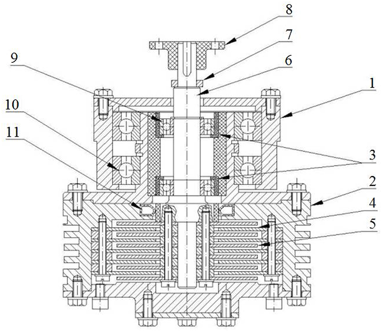
Figure 7. Design solution of a prototype of the clutch: 1, bearings casing; 2, clutch casing; 3, insulating sleeves for shaft bearings; 4, discs fixed to the casing; 5, discs placed on the shaft; 6, shaft; 7, sliding ring; 8, flexible coupling; 9, shaft's bearing; 10, clutch's bearing; 11, sealing ring.
Such a constructional solution is beneficial because of the sealing. Between the discs, spacer rings were used, and exchanging them enables changes in the width of the working gap. The “+” pole of the high voltage power supply was connected to the clutch's shaft by a brush and sliding ring, while the pole “–” was connected to the clutch's casing. In order to isolate the driving part from the driven part, the outer ring of the bearings fixed on the shaft were placed in the sleeves made of a material which is an excellent electrical insulator. To decrease the costs of producing the clutch, the discs were fixed with screws instead of typically used splines. In order to increase the thermal capacity and to facilitate dissipating the heat from the clutch's working gaps, the casing walls were made to be much thicker than would be necessary to ensure sufficient mechanical strength and rigidity.
Materials Used
Due to good electrical and thermal conductivity, most of the parts of the clutch's prototype were built with metal. Clutch discs were made of austenitic stainless steel with designation 304 according to the ASTM/AISI standard. The 304 stainless steel has approximately 19% chromium and 10% nickel as its major alloying additions and is resistant to corrosion while maintaining its strength at high temperatures. The starting material for the production of the clutch's discs was a cold-rolled sheet with a smooth surface. The discs were cut out of the sheet using abrasive water jet machining. Then, the discs were polished. Grinding of this material is not advised due to the fact that it is too soft for this process. The casing and shaft of the clutch were made by machining from steel designed as 403 by ASTM/AISI standards. The 403 stainless steel has 11% chromium and 1% manganese. A higher carbon content means that the 403 stainless steel has higher strength and higher wear resistance compared to the 304 stainless steel.
Isolating sleeves of the bearings and flexible coupling of the clutch's shaft with the motor shaft were made with a material called Poliamid (PA6). The sealing ring was 3D-printed with a material called ABS (Akrylonitrylo-Butadieno-Styren) (Kotlinski et al., 2013).
Tests on the Clutch With ER Fluid
Building the Test Rig
The test rig used for the purpose of testing the prototypical clutch consisted of a controlled electric motor on whose shaft a driving part of the clutch with ER fluid was installed. The driven part was connected to the lever pressing on the force sensor. The accuracy of the force sensor position relative to the lever was 0.1 mm, which resulted in an error of < 0.1%.
The value of electric voltage was applied from the high voltage power supply, whose poles were connected interchangeably with discs of the prototypical clutch. The power supply also enabled the measurement of leakage current. In the casing of the viscous clutch with ER fluid, a thermometer was installed to enable measurements of ER fluid's temperature. Measurement of the relative air humidity was realized with a humidity transducer set in close proximity of the clutch. Angular velocity was read with the aid of an encoder of the electric motor. Accuracies of measuring devices used in the test rig are listed in Table 6. All measured values were recorded over time based on a computer measurement system. The scheme of the test rig is presented in Figure 8.
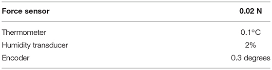
Table 6. Accuracy of measuring devices.
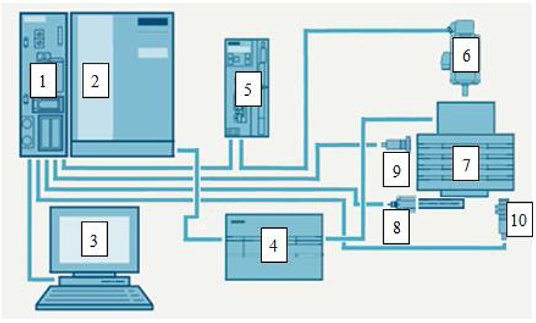
Figure 8. Scheme of the test rig: 1, PLC; 2, input/output cards; 3, computer set with software; 4, high voltage power supply; 5, servo drive controller; 6, servo drive; 7, tested clutch with ER fluid; 8, force sensor; 9, humidity sensor; 10, temperature sensor.
Workplace Tests
The characteristics of the viscous clutch with the ER fluid as were determined based on formulas (13) and (14) for the read values of force F depending on the angular velocity ω for chosen constant values of electric voltage U, Figure 9. The measurements were performed in a constant temperature of the fluid and constant relative humidity w. In comparison, Figure 9. shows additionally characteristics made with a measurement device whose scheme can be seen in Figure 2.
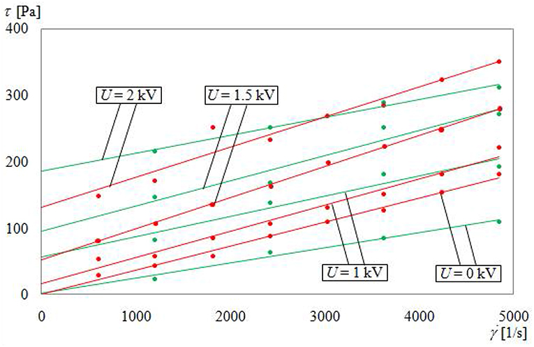
Figure 9. Dependence of τ from for T = 20 °C and w = 30%: green color, measurement devices; red color, viscous clutch with ER fluid.
As can be seen from the charts presented in Figure 9, differences between lines concerning measurement device and lines concerning the clutch with ER fluid are not large, even if there are substantial differences in dimensions and shape of working gaps. The average relative error was 12%. It is also essential to notice that the range of changes in shear stress τ caused by changing the voltage U from 0 to 2.5 kV is 30% larger than the range of changes in shear stress τ caused by changes in angular velocity ω.
Durability tests of the prototype clutch with ER fluid have shown that insulating material needs to be carefully selected, and so do materials for sliding ring and brush. Initially the insulating material was Tekstolit (TcF-1), characterized by a large electrical resistance and good machinability. To simplify the clutch's construction, a copper brush cooperating directly with the shaft was also used. However, during the tests it turned out that due to moisture deposited on the sleeve, exposed to high voltages, the material was partially charred on the surface, and the conductive paths created this way largely decreased the insulating properties. After replacing Tekstolit (TcF-1) with Poliamid (PA6) material, there was no decrease in insulating properties. The tests have also shown that using the copper brush in cooperation directly with the shaft is the cause of electrical breakdowns occurring under a relatively low voltage, around 1.5 kV, due to the fact that the products of wear were getting inside the clutch with the ER fluid. To prevent this, the sliding ring was made of bronze and the brush was made of graphite, due to its good lubricating properties. After this change there were no occurrences of electrical breakdowns caused by products of wear.
Recommendations for the Selection of Materials
While choosing an ER fluid to use in a controlled clutch, one needs to select a fluid whose shear stress τ insignificantly depends on the shear rate . As was shown in previous research (Nakamura et al., 2002, 2004), the larger the dependence, the more problematic the control of the device using the ER fluid is. The requirement is best met by heterogeneous ER fluids whose solid phase is chemically clean starch. The disadvantage of this type of fluid is a large sensitivity to humidity and low durability. While choosing the ER fluid to control viscous clutch, a factor that needs to be taken into consideration is also the fact that the torque M, transmitted by the clutch, is the sum of two components, the first of which depends on μp·ω with the second depending on τ0, being the function of voltage U. If the clutch is to be controlled by shifting the voltage U, the fluid that is chosen needs to have the largest τ0/μ0 ratio, while for a clutch controlled by changes in angular velocity ω needs to have the smallest possible τ0/μ0 ratio.
While choosing the materials for insulating elements for the viscous clutch with ER fluid, attention must be paid to their insulating strength, low thermal expansion ensuring shape stability when exposed to high temperature, good chemical resistance to oils, large mechanical durability and good machinability. It needs to be taken into consideration that plastics are good electrical insulators as well as thermal insulators. Using insulating materials hinders dissipation of the heat generated as a result of mutual friction of the particles, the friction between the particles and walls of the working gap, and electrical current in the ER fluid. When determining the thickness of the walls of the insulating elements, one needs to take into consideration the fact that the thicker the wall, the lesser the possibility of electrical breakdowns. However, this renders the heat dissipation conditions worse. Currently, a great facilitation is the possibility to create insulating elements of complicated shapes with 3D printing methods due to the fact that most plastics used in this technology have good insulating properties.
Using metal materials is connected to the possibility of corrosion of the metal parts of the clutch, especially the ones working in an increased temperature, whose products conducting electricity after getting into the ER fluids can cause an increase in leakage current and occurrences of electrical breakdowns. It is expedient to use metals and alloys resistant to corrosion. In the case of occurrences of frictional contacts of the clutch's elements, it is important to take notice of the fact that the wear products can hinder correct operation of the clutch.
Conclusions
Controlling force F by means of the clutch with the ER fluid can be realized by altering the angular velocity of the motor and by changing the high voltage of the electric current applied to the discs, because both the increase in the angular velocity and the increase in the electrical voltage cause an increase in shear stress in the ER fluids and an increase in the torque transmission to the lever. However, controlling by changes in voltage is faster and enables a control range that is 30% larger. The introduced way of controlling the force can be practically used, as it allows a fluent change of the force from zero to maximal value.
The designed mathematical models, although simple, are precise enough to be used for optimization of the construction of the clutch with ER fluid. Differences between the test results of the clutch with ER fluids and measurement device reach 12% on average, but they can be rendered acceptable due to significant differences in the dimensions and shapes of working gaps. It can be acknowledged that the test results gained with the aid of measurement devices can be used for designing clutches with ER fluid.
The assumed optimization methods for the dimensions of viscous clutch with ER fluids, consisting of a random proportional enlargement of the model clutch turned out to be useful for designing the viscous clutch with ER fluid. It is important to emphasize that the optimization conducted this way, by using two different objective functions, provided very similar results.
Due to the complex construction of the viscous clutch with ER fluids, it is vital to use construction materials with conducting properties as well as materials with insulating properties. However, not all materials with these abilities can be used in clutches with ER fluid. The introduced guidelines can be useful while choosing materials for construction of a viscous clutch with ER fluids. As shown by the conducted works, in practice it is vital to support the choice of materials by durability tests of the prototypical clutches.
Based on the results of the conducted tests it can be presumed that further works aiming to expand usage of viscous clutches with ER fluids in machines and devices need to focus especially not only on the optimal shape of the clutches with ER fluids, but also on proper choice of ER fluids as well as other construction materials.
Author Contributions
AK and ZK contributed conception and design of the study. GM and JZ conducted optimization analysis. PM performed ANSYS calculations. AK, ZK, KO, and AO carried out tests. ZK, AO, and KO wrote the first draft of the manuscript. S-BC contributed to manuscript revision, read and approved the submitted version.
Funding
This research had received funding from the Polish-Taiwanese/Taiwanese-Polish Joint Research Project no. PBWLA/2016/019.
Conflict of Interest Statement
The authors declare that the research was conducted in the absence of any commercial or financial relationships that could be construed as a potential conflict of interest.
References
Assadsangabi, B., Daneshmand, F., Vahdati, N., Eghtesad, M., and Bazargan-Lari, Y. (2011). Optimization and design of disk-type MR brakes. Int. J. Auto. Tech-Kor. 12, 921–932. doi: 10.1007/s12239-011-0105-x
Avraam, M., Horodinca, M., Romanescu, I., and Preumont, A. (2010). Computer controlled rotational MR-brake for wrist rehabilitation device. J. Intel. Mat. Syst. Struct. 21, 1543–1557. doi: 10.1177/1045389X10362274
Bocińska, M., Wyciślik, H., Osuchowski, M., and Płocharski, J. (2002). Influence of surfactans on properties of electrorheological fluids containing polyaniline. Int. J. Mod. Phys. B. 16, 2461–2467. doi: 10.1142/S0217979202012517
Böse, H., Gerlach, T., and Ehrlich, J. (2013). Magnetorheological torque transmission devices with permanent magnets. J. Phys. Conf. Ser. 412:012050. doi: 10.1088/1742-6596/412/1/012050
Bucchi, M. F., Forte, P., and Frendo, F. (2017). Geometry optimization of a magnetorheological clutch operated by coils. P. I. Mech. Eng. LJ Mat. 231, 100–112. doi: 10.1177/1464420716665650
Carlson, J. D. (1997). “Magnetorheological fluid actuators” in Adaptronics and Smart Structures, ed H. Janocha (Berlin; Heidelberg: Springer Verlag, 184–204.
Chen, S., Huang, J., Jian, K., and Ding, J. (2015). Analysis of influence of temperature on magnetorheological fluid and transmission performance. Adv. Mater. Sci. Eng. 2015, 1–7. doi: 10.1155/2015/583076
Choi, Y. T., and Wereley, N. M. (2015). Drop-induced shock mitigation using adaptive magnetorheological energy absorbers in corporating a time lag. J. Vib. Acoust. 137:7. doi: 10.1115/1.4028747
Conrad, H. (1993). Electrorheological fluids: characteristics, structure and mechanisms. ASME Fluids Eng. Div. Electrorheol. Flows 164, 99–113.
Erol, O., and Gurocak, H. (2011). Interactive design optimization of magnetorheological brake actuators using the Taguchi method. Smart Mater. Struct. 20:105027. doi: 10.1088/0964-1726/20/10/105027
Fernández, M. A., and Chang, J. Y. (2016). “Development of magnetorheological fluid clutch for robotic arm applications,” in IEEE 14th International Workshop on Advanced Motion Control.
Fertman, V. E. (1990). Magnetic Fluids Guidebook: Properties and Applications. New York, NY; Washington, DC; Philadelphia, PA; London: Taylor and Francis Inc.
Gao, F., Liu, Y. N., and Liao, W. H. (2017). Optimal design of a magnetorheological damper used in smart prosthetic knees. Smart Mater. Struct. 26:035034. doi: 10.1088/1361-665X/aa5494
Horvath, P., and Torőcsik, D. (2011). Optimization of a disc-type magneto-rheological clutch. Sci. Proc. Faculty Mech. Eng. STU Bratislava 19, 106–111. doi: 10.2478/v10228-011-0018-8
Jing, Z., Sun, S., Ouyang, Y., Zhang, S., Li, W., and Zheng, J. (2018). Design and modeling analysis of a changeable stiffness robotic leg working with magnetorheological technology. J. Intel. Mat. Syst. Struct. 29, 3725–3736. doi: 10.1177/1045389X18798958
Kavlicoglu, B., Gordaninejad, F., Evrensel, C. A., Cobanogulu, N., Xin, M., Fuchs, A., et al. (2002). A high-torque magneto-rheological fluid clutch. Proc. SPIE Conference Smart Mater. Struct. 4697:472674. doi: 10.1117/12.472674
Kim, K. S., Choi, S. B., and Cho, M. S. (2002). Vibration control of a vire cut discharge machine using ER brake acuator. J. Intel. Mat. Syst. Struct. 13, 316–322. doi: 10.1177/1045389X02013010002
Kim, W. H., Park, J. H., Kim, G. W., Shin, C. S., and Choi, S. B. (2017). Durability investigation on torque control of a magnetorheological brake: experimental work. Smart Mater. Struct. 26:037001. doi: 10.1088/1361-665X/aa59d8
Kotlinski, J., Migus, M., Kesy, Z., Kesy, A., Hugo, P., Deez, B., et al. (2013). Fabrication of hydrodynamic torque converter impellers by using the selective laser sintering method. Rapid Prototyping J. 19, 430–436. doi: 10.1108/RPJ-04-2011-0043
Kumbhar, B. K., Patil, S. R., and Sawant, S. M. (2015). Synthesis and characterization of magneto-rheological (MR) fluids for MR brake application. Eng. Sci. Technol. Int J. 18, 432–438. doi: 10.1016/j.jestch.2015.03.002
Lara-Prieto, V., Parkin, R., Jackson, M., Silberschmidt, V., and Kȩsy, Z. (2010). Experimental study of adaptive MR cantilever sandwich beams for vibration control applications. Smart Mater. Struct. 19:015005. doi: 10.1088/0964-1726/19/1/015005
Li, Y., Li, J., Li, W., and Samali, B. (2013). Development and characterization of a magnetorheological elastomer based adaptive seismic isolator. Smart Mater. Struct. 22:035005. doi: 10.1088/0964-1726/22/3/035005
Liu, B., Li, W. H., Kosasih, P. B., and Zhang, X. Z. (2006). Development of an MR-brake-based haptic device. Smart Mater. Struct. 15:1960. doi: 10.1088/0964-1726/15/6/052
Madeja, J., Kesy, Z., and Kesy, A. (2011). Application of electrorheological fluid in a hydrodynamic clutch. Smart Mater. Struct. 20:105005. doi: 10.1088/0964-1726/20/10/105005
Mangal, S. K., Munjal, K., and Sharma, V. (2016). On-state torque optimization for synthesized MR fluid. Int. J. Eng. Res. Appl. 6, 9–14(Pt 5). Available online at: www.ijera.com
Mikkelsen, A., Wojciechowski, J., Rajnak, M., Juraj Kurimsky, J., Khobaib, K., Kertmen, A., et al. (2017). Electric field-driven assembly of sulfonated polystyrene microspheres. Materials 10, 1–17. doi: 10.3390/ma10040329
Milecki, A., Sedziak, D., and Ortmann, J. (2005). Controllability of MR shock absorber for vehicles. Int. J. Vehicle Des. 38, 222–233. doi: 10.1504/IJVD.2005.007294
Nakamura, T., Saga, N., and Nakazawa, M. (2002). Impedance control of a single shaft-type clutch using homogeneous electrorheological fluid. J. Intel. Mat. Syst. Struct. 13, 465–469. doi: 10.1106/104538902029068
Nakamura, T., Saga, N., and Nakazawa, M. (2003). Thermal effects of a homogeneus ER fluid device. J. Intel. Mat. Syst. Struct. 14, 87–91. doi: 10.1142/9789812777546_0037
Nakamura, T., Saga, N., and Nakazawa, M. (2004). Variable viscous control of a homogeneous ER fluid device considering its dynamic characteristics. Mechatronics 14, 55–68. doi: 10.1016/S0957-4158(02)00095-8
Nguyen, Q. H., and Choi, S. B. (2010). Optimal design of an automotive magnetorheological brake considering geometric dimensions and zero-field friction heat. Smart Mater. Struct. 19:115024. doi: 10.1088/0964-1726/19/11/115024
Olszak, A., Osowski, K., Kȩsy, A., and Kȩsy, Z. (2016a). Experimental researches of hydraulic clutches with smart fluids. Int. Rev. Mech. Eng. 10, 364–372. doi: 10.15866/ireme.v10i6.8421
Olszak, A., Osowski, K., Kesy, Z., and Kesy, A. (2018). Investigation of hydrodynamic clutch with MR fluid. J. Intel. Mat. Syst. Struct. 30, 155–168. doi: 10.1177/1045389X18803463
Olszak, A., Ziabska, E., Osowski, K., Kȩsy, A., and Kȩsy, Z. (2016b). Durability of hydraulic clutches filled with electrorheological fluids. Tech. Trans. Mech. 113, 87–101. doi: 10.4467/2353737XCT.16.288.6120
Park, E. J., Falcao Da Luz, L., and Suleman, A. (2008). Multidisciplinary design optimization of an automotive magnetorheological brake design. Comput. Struct. 86, 207–216. doi: 10.1016/j.compstruc.2007.01.035
Park, E. J., Stoikov, D., Falcao da Luz, L., and Suleman, A. (2006). A performance evaluation of an automotive magnetorheological brake design with a sliding mode controller. Mechatronics 16, 405–416. doi: 10.1016/j.mechatronics.2006.03.004
Płocharski, J., Drabik, H., Wyciślik, H., and Ciach, T. (1997). Electrorheological properties of polyphenylene suspensions. Synthet. Metals 88, 139–145.
Raju, A., Md Meftahul, F., and Yancheng, L. (2016). Advancement in energy harvesting magneto-rheological fluid damper: a review. Korea-Australia Rheol. J. 28, 355–379. doi: 10.1007/s13367-016-0035-2
Saito, T., and Ikeda, H. (2007). Development of normally closed type of magnetorheological clutch and its application to safe torque control system of human-collaborative robot. J. Intel. Mat. Syst. Struct. 18, 1181–1185. doi: 10.1177/1045389X07084755
Sapiński, B., Rosół, M., and Wȩgrzynowski, M. (2016). Evaluation of an energy harvesting mr damper-based vibration reduction system. J. Theor. App. Mech-Pol. 54, 333–344. doi: 10.15632/jtam-pl.54.2.333
Sarkar, C., and Hirani, H. (2013). Synthesis and characterization of antifriction magnetorheological fluids for brake. Defence Sci. J. 63, 408–412. doi: 10.14429/dsj.63.2633
Smith, A. L., Ulicny, J. C., and Kennedy, L. C. (2007). Magnetorheological fluid fan drive for trucks. J. Intel. Mat. Syst. Struct. 18, 1131–1136. doi: 10.1177/1045389X07083136
Sohn, J. W., Gang, H. G., and Choi, S. B. (2018). An experimental study on torque characteristics of magnetorheological brake with modified magnetic core shape. Adv. Mech. Eng. 10, 1–8. doi: 10.1177/1687814017752222
Sohn, J. W., Jeon, J., Nguyen, Q. H., and Choi, S. B. (2015). Optimal design of disc-type magnetorheological brake for mid-sized motorcycle: experimental evaluation. Smart Mater. Struct. 24:085009. doi: 10.1088/0964-1726/24/8/085009
Song, W., Wang, S., Choi, S. B., Wang, N., and Xiu, S. (2018). Thermal and tribological characteristics of a disc-type magnetorheological brake operated by the shear mode. J. Intel. Mat. Syst. Struct. 30, 722–733. doi: 10.1177/1045389X18770740
Takesue, N., Furushoa, J., and Inoue, A. (2003). Influence of electrode configuration and liquid crystalline polymer type on electrorheological effect. J. App. Phys. 94, 5367–5373. doi: 10.1063/1.1605811
Weiss, D. (1993). “High strength magneto and electro-rheological fluids,” in SAE Technical Paper, International Off-Highway & Powerplant Congress & Exposition (Milwaukee, WI), 932451. doi: 10.4271/932451
Keywords: viscous clutch, smart fluids, ER fluids, optimization, numerical calculations
Citation: Olszak A, Osowski K, Motyl P, Mędrek G, Zwolak J, Kęsy A, Kęsy Z and Choi S-B (2019) Selection of Materials Used in Viscous Clutch With ER Fluid Working in Special Conditions. Front. Mater. 6:139. doi: 10.3389/fmats.2019.00139
Received: 30 October 2018; Accepted: 29 May 2019;
Published: 20 June 2019.
Edited by:
Marcelo J. Dapino, The Ohio State University, United StatesReviewed by:
Yu Tian, Tsinghua University, ChinaRongjia Tao, Temple University, United States
Jianbo Yin, Northwestern Polytechnical University, China
Copyright © 2019 Olszak, Osowski, Motyl, Mędrek, Zwolak, Kęsy, Kęsy and Choi. This is an open-access article distributed under the terms of the Creative Commons Attribution License (CC BY). The use, distribution or reproduction in other forums is permitted, provided the original author(s) and the copyright owner(s) are credited and that the original publication in this journal is cited, in accordance with accepted academic practice. No use, distribution or reproduction is permitted which does not comply with these terms.
*Correspondence: Seung-Bok Choi, c2V1bmdib2tAaW5oYS5hYy5rcg==