 Weiguo Zhang
 Guodong Zhu2
- 1School of Optoelectronic Engineering, Chongqing University, Chongqing, China
- 2Chongqing Institute of Green and Intelligent Technology, Chinese Academy of Sciences, Chongqing, China
Spiral-structure metamaterial (SSM) is of great importance, however, there are fewer methods to fabricate SSM due to limitations of material particularity and working accuracy. In this paper, a systematic scheme for fabricating SSM is proposed by employing the metal mold making with diamond-based ultra-precision turning technique and then molding replication method. By studying the path planning algorithm of the turning, molding error law, and a technique of how to compensate for the error, a solution for SSM is consequently formed. Our experimental results show a satisfying SSM with a surface roughness under 5 nm and a surface shape error under 0.63% of the designed wavelength (30 um). Moreover, this SMM element is processed within 10 min, with low cost materials and processes. Based on these advantages, our SSM processing scheme shows a remarkable potential in precise fabricating phase plates and industrialized application of terahertz metamaterial in the future.
Introduction
Spiral-structure metamaterial (SSM) can modulate the beam of an electromagnetic plane wave into a spiral wave by controlling the spiral state of the electromagnetic wave. In this paper, we propose a method to fabricate the SSM in a wavelength range in 30 um ~1 mm, which has an important application in many fields, such as quantum optics, communication, and sensing detection [1–4]. The relevant characteristic parameters require the fabrication between micro-machining and traditional machining. It is therefore difficult to use an existing fabrication technique to make the SSM with high precision and efficiency.
It was expected that the fabrication of SSM would need to involve the microlithography method and ultra-precision machining technique. For the microlithography technique, the available materials in the terahertz region mainly include quartz and silicon [5–9]. This technique has high machining precision with a quartz-based etching depth under 10 um and a silicon-based etching depth under 50 um. However, at such etching depths, the application requirement of the terahertz waveband is difficult to meet. Additionally, there are some other shortcomings when using the etching technique, such as tedious processing steps, long processing period, and a high cost. As for the ultra-precision machining technique, by employing the diamond cutter equipment which can be controlled with nanometer precision, both the processing area and adjustable precision will be greatly improved [10–13]. In fact, the diamond cutter is not suitable for terahertz materials such as polymethylpentene, polyethylene (PE), polypropylene, and polytetrafluoroethylene, while this cutter shows an excellent machinability in some other materials, for instance, metals and crystals [14, 15]. The high-polymer-based terahertz material may cause obvious wear to the diamond cutter and may, consequently, influence the forming quality of SMM.
Combining the ultra-precision machining technique with the thermoplasticity of high-polymer -based materials, we present an ultra-precision replication method for fabricating the SSM. By applying the single-point diamond turning mold and using the error compensation technique, the error between device and design parameters can be reduced, and the SSM can be fabricated with high efficiency, high precision, and at a low cost.
Principle of the Ultra-Precision Replication Technology for SSM
The Principle of the ultra-precision replication technology is shown in Figure 1. The whole fabrication process contains the fabrication of a diamond turning mold, replication of a high polymer device, demolding, and shape modification. Herein, the metal mold for turning was 7,075 aluminum material. The turning process is composed of substrate leveling, rough turning, and fine turning. It is therefore possible to improve the process efficiency of the mold and to reduce the wear of the cutter, while the homogeneity, surface form precision, and surface roughness of the mold are well controlled. Molding replication is accomplished through the tooling design, preheating, molding, heat preservation, and annealing. To realize the precise printing of the polymer material surface graphics, it is necessary to clarify the rule of distortion between the printing device and mold, which can provide a basis for mold error compensation technology.
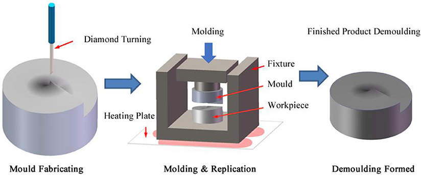
Figure 1. Principle diagram of the SSM processing technique.
Diamond Ultra-Precision Turning Technology for The SSM Mold
In the fabrication of the SSM mold, some parameters, such as surface roughness, surface shape precision, and machining efficiency, will have an influence. The key factor is the planning algorithm of the cutting tool path. In this paper, we propose two processing methods, i.e., the radial feeding method and the angular feeding method. A comparative analysis of the characteristics of these two methods is conducted.
Radial Feeding Method
For the radial feeding method, with every machining process of the cutter, the sample position remains unchanged, and the depth is equal in the same radius direction. With every cutting, the sample is rotated with a fixed angle by C axis, as shown in Figure 2. The relationship between the depth and angle is given by Equation (1):
Where hθ is the depth corresponding to a rotation angle θ, which starts from the highest point, λ is the terahertz wavelength, and n is refractive index of the high polymer material with respect to terahertz wave.
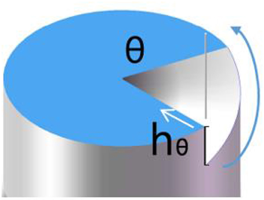
Figure 2. Diagram of the radial feeding process. White arrows represent the cutting direction of the cutter, while the blue curved arrows represent the marching direction of the work piece. The work piece is rotated by a tiny angle increment dθ after cutting with a radius length by the planning cutter.
Angular Feeding Method
The principle of the angular feeding method is shown in Figure 3. During the machining process of the cutter, the work piece always remains rotational. By using the slow tool servo mode, the cuter is then processed with a fixed length in the direction from the external diameter to the center of the SSM over a period of a 360° rotation. After rotating the sample by an angle θm, the relation between the cutting depth of the cutter and rotational angle is shown as in Equation (2):
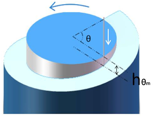
Figure 3. Diagram of the angular feeding process. Blue curved arrows represent the cutting direction of the cutter, while the white arrows represent the motion track of the cutter along the cutting-in direction. Here the feed direction of sample is determined as the radial direction. After a rotation period, the sample is moved by a tiny distance ds along a plane perpendicular to the cutter away from the original point.
Here hθm is the depth corresponding to a rotation angle θm, which starts from the highest point (zero), λ is the terahertz wavelength, n is the refractive index of the high polymer material with respect to the terahertz wave, and m is the number of turns of the work piece.
Comparison of the Cutting Methods
In the SSM process, some key parameters are presented, such as low surface roughness, tiny surface profile error, and high processing efficiency. As for the surface profile error, both the radial feeding method and angular feeding method are restricted by the positioning precision of the equipment and the radius of curvature of the tool's nose. In the context of using similar equipment and a fixed cutter, there is a negligible difference between them. And for the surface roughness of the mold, it mainly relies on the radius of curvature of the cutter nose, the linear velocity in cutting, and the feeding velocity of the cutter.
For the radial feeding method, the linear velocity of the cutter is equal to the planning velocity of Y axis in a diamond lathe. Moreover, the liner velocity in cutting at a point is equal to each other. The feeding velocity of the cutter is the arc length from the center to edge of the work piece for each rotation. The feeding velocity in each point is proportional to a distance from the point to the center. In other words, with the increase of feeding velocity of the work piece, the roughness in processing is also increased.
For the axial spiral cutting method, the cutter is used for discrete cutting. Once the phase plate is rotated, the orthogonal coordinates are then transformed into the polar coordinates. The system obtains discrete points in terms of radian and traces the processing depth at each point. After finishing a period of processing, the cutter is propelled with some distance from the edge to the center of the work piece. When using discrete cutting, the influence of the linear velocity to surface roughness of the work piece can be considered with little focus due to the fast-tracking velocity. In contrast, the feeding velocity acts as the key factor influencing surface roughness, containing two velocity components in the axial and radial directions. The feeding velocity in the axial direction mainly relies on the revolving speed of the work piece and the point density. With the decrease in revolving speed and the increase of point density, the velocity is then decreased, resulting in low surface roughness on the work piece. Here the point density is related to the distance between a point and the center of a circle, and to the density in dividing angles. A large point density is obtained by reducing this distance and increasing the angle density. As for the feeding velocity in the radial direction, it mainly relies on the marching velocity of the cutter in radial direction. In principle, a large velocity leads to large surface roughness.
In the case of reaching the precision limit of the equipment and process, it is possible to fabricate the SSM with low surface roughness and form error via the radial feeding method or the angular feeding method. However, from the point of processing efficiency, there is an obvious difference between the two methods. To attain similar surface roughness, the discrete precision in two methods was chosen as the rotational resolution of 1 arc s. For the angular feeding method, the processing time is calculated as:
Here r is the radius of spiral phase plate, and v is the linear velocity of Y axis that is ≤ 1,000 mm/min in general, which satisfies T1 ≥ 14.4πr. When working on the same samples, it is possible to form a same surface roughness through the angular feeding method. Based on this technology, the radial feeding is calculated at the edge for a period of a rotation. Hence, the radial feeding process time is given by:
Where f is the servo tracking frequency of the cutter that is <1,000 Hz in general, therefore T2 ≥ 108/π. If T1 ≤ T2 (i.e., 14.4πr ≤ 108/π), which corresponds to a conversion result r ≤ 7.5/π, so it is more efficient to use the radial feeding method. In contrast, if r ≥ 7.5/π2, it is more suitable to use the angular feeding method.
Compression Molding of Polyethylene SSM
Polyethylene (PE) is kind of material with a good chemical and physical property in the terahertz region, such as high transmission, good dielectric properties, corrosion resistance, and radiation resistance. The refractive index is 1.54 in a broad spectral range. In this paper, PE material is utilized to illustrate how to fabricate the terahertz SSM. In order to achieve the SSM fabrication in batches, we have used the SSM mold to replicate a PE terahertz element.
Temperature Control Processing
The molding process diagram is shown in Figure 4. We first designed and made a work fixture and assembled the metal spiral phase plate and the PE substrate, as shown in Figure 4, followed by a heating and pressure treatment in the molding apparatus. Hence, a conformal deformation on the PE substrate is induced in terms of the surface morphology of the metal mold. Ultimately, the spiral structure on the surface of the PE substrate is cooled and solidified after the pressure treatment. We consequently disassembled the fixture and took out the PE SSM.
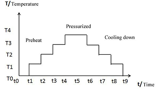
Figure 4. Molding process diagram.
The main factors affecting the terahertz molding precision includes heating speed, temperature, heat preservation time, pressure size, and cooling speed, etc.
Fixture Design
When molding the SSM, we needed to keep the mold and PE substrate fixed, to avoid the relative displacement. Because the displacement will cause SSM deformation, a special fixture needed to be designed. The requirements for the fixture include the following: (1) The material of the mold should be resistant to high temperature; (2) the substrate and the mold need to be fixed, so that there is no lateral sliding between them when the pressure is forced, and (3) an exhaust mechanism is needed in the fixture. The pressure process gas will not be closed in the micro-structure of the sample, which will affect the die pressure accuracy of the micro-structure. (4) The pressure of the die press device can be transmitted vertically to the mold and substrate, to maintain the uniformity of the force.
In accordance with the above requirements, the fixture scheme that was designed is shown in Figure 5. The fixture consists of a substrate fixed plate, a mold fixed plate, and a limited-position sleeve. Both the PE substrate and the mold have a base plate fixed slot. The depth of the slot is slightly less than the thickness of the substrate and the mold. The height of the sleeve limits the final sample processing height, and the diameter of the limiting sleeve controls the slip between the substrate and the mold. In order to make an exhaust mechanism, a vent hole on the limiting sleeve should be opened.
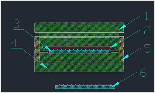
Figure 5. Diagram of the fixture, 1 is the mold fixed plate, 2 is the mold, 3 is the PE substrate, 4 is the substrate fixed plate, 5 is the limited-position sleeve, and 6 is the fabricated SSM.
Demolding of the SSM
In order to ensure that there is no adhesion between the mold and the substrate surface during the demolding process, we needed to make an anti-adhesion layer on the mold surface. Because some Fluorinated polymer materials have excellent characters such as high temperature tolerance and no adhesion with other material, we coated the polymer which contains fluorine element to make an anti-adhesion layer on the aluminum mold. The anti-adhesion layer should be as thin as possible, so that the polymer layer does not affect the structure on the mold. We used the steam plating coating method to make the thin layer.
In order to reduce the mechanical damage of molds and SSM components while demolding, we first make the PE substrate structure, the fixture and the mold are cooled to room temperature, thus all the elements are stable. Second, we used the mechanical devices to ensure that the demolding force direction was perpendicular to the surface of the PE substrate and mold, and the mold and the SSM were separated vertically, which can reduce the mechanical damage caused by the lateral sliding in the demolding process.
Processing Experiment of SSM
In order to present a systematic processing method, the following parameters were used: the topological charge number is 1, the diameter is 50 mm, and the depth difference between two sides of the total step is approximated as 55.56 um, which corresponds to a wavelength of 30 um.
Experiment of the Cutting Tool Wear in Metal and PE Cutting
The cutting properties of metals and PE materials were studied through an experiment. The cutting speed was set as 10 mm/s, the cutting depth is 50 um, the cutting length is 50 mm per round, and the diamond tools with curvature radius is 0.4 mm. After a total of 10 rounds of cutting, the tool wear was observed under a microscope, as shown in Figure 6. Figure 6a is the picture of the tool after the aluminum has been cut, the results show that the tool has little wear. Figure 6b shows the tool after the PE has been cut, and the tool wears significantly and a gap phenomenon appears, which shows that the diamond turning methods cannot be used in PE materials processing. Therefore, the molding method is necessary in PE SMM fabrication.
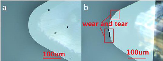
Figure 6. (a) Is the picture of tool's wear after cutting aluminum; (b) is the picture of tool's wear after cutting PE material.
Experiment of the Radial Feed Method and Angular Feed Method
Taking the SSM with 50 mm diameter and 55.56 um total depth as an example, this paper adopted the 7,075 Aluminum Material as the substrate and carried out the diamond ultra-precision cutting of the mold. We employed the diamond lathe from Moore company in US (Nanotech350FG) and made the mold turning experiment. After processing, the surface profile data of SSM were measured by the white-light interferometer, and then the obtained data were processed and analyzed by MATLAB software. Due to the limitation of the FOV of measurement equipment and data volume of the analysis, we measured the area of 5 × 4 mm in the middle of the SSM. In theory, the pattern distribution outside 5 mm is the same as that along radial direction. The periodicity error caused by tool marks is proportional to the radius. The results of the processing are shown in Figure 7. Figure 7A is a three-dimensional profile produced by the angular feeding method. The scheme of one-step roughing, one-step semi-finishing, and one-step finishing were adopted. The cutting depth was 40, 10, and 5 um, respectively, and the feed speed was 10, 5, and 2 mm/min, and the turning speed of the lathe was 20 rpm. The overall mold processing time was 20 min, and the precision of the pattern surface error PV value was 700 nm, as shown in Figure 7B, and the surface roughness Ra value was about 4.1 nm, as shown in Figure 7C. Figure 7D is a three-dimensional contour map produced by the radial feeding method. The scheme of one-step roughing, one-step semi-finishing, and one-step finishing was adopted. Each cutting depth was 40, 10, and 5 um, respectively, and each step was 0.5, 0.2, and 0.1°. The cutting speed was 600 mm/min. After each line had been cut, the tool must return to the center before the next line can be cut, and the total processing time was 15 h. The three-dimensional profile of SMM is shown in Figure 7D, and the surface accuracy error PV value was about 4.78 um, which is shown in Figure 7E. Finally, the surface roughness Ra value was about 27.5 nm, as shown in Figure 7F. The experimental results are in good agreement with the theoretical results in Chapter 2. In the process of making SMM, the machining method of rotating around the axis had obvious advantages in machining efficiency and accuracy.
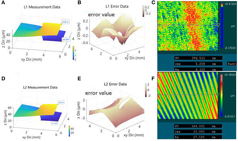
Figure 7. Graph (A) is the measurement data of SSM which is processed by the method of angular feeding, it can clearly be seen that the SSM is a spiral structure; Graph (B) is the error analysis data between graph (A) and the theoretical data, horizontal coordinate represents the measurement data location on the plane of SSM, and vertical coordinate represents the error data value, the PV value of the error data is about 0.7 um; Graph (C) is the roughness data of the SSM that was fabricated by angular feeding, this figure was taken by white light interferometer under 10× objective, and the figure size is about 0.4 × 0.3 mm. The color bar represents the roughness value of the SSM, and the PV, rms, and Ra values which were shown in the table was calculated by the instrument's own software. From the table we can see that the Ra value of roughness is about 4.1 nm. Graph (D) is the measurement data of SSM which is processed by the method of radial feeding, it can clearly be seen that the SSM is a spiral structure; Graph (E) is the error analysis data between graph (D) and the theoretical data, it is the same format as figure. (B), the PV value of the error data is about 4.1 um; Graph (F) is the roughness data of the SSM that is fabricated by the radial feeding method, it is the same format as figure. (C), and the Ra value of roughness is about 27.5 nm.
Experiment of PE SSM Molding Processing
After the mold of SSM was fabricated, we fabricated the PE material SSM using the precision molding method. First, we assembled these elements and then used the sleeve to fix them. Afterwards, the assembled work piece was placed into MYLMR-3300 molding equipment, and we improved the temperature from the indoor temperature. Note that a temperature of 20°C should be maintained for 1 min for each improvement. When the temperature reached 130°C, we imposed a pressure of 0.22 MPa on the work piece for 5 min. With this pressure, we refrigerated the work piece to a temperature <40°C, with a cooling rate of 20°C/min. Ultimately, by repealing the pressure treatment and disassembling these elements, the molded SSM was taken out. The graph of the mold and PE SSM is shown in Figure 8. The picture of the SSM mold is shown in Figure 8a, and the step height of the mold is shown in Figure 8c, which is about 55.41 um. Figure 8b is the picture of the molded PE SSM, and the molded PE SSM step height is shown in Figure 8d, which is about 55.37 um. From these data we could see that the step height error between the mold and PE SSM was only about 40 nm, which was about 0.1% in the total step height. The step height error between PE SSM and the theoretical value was about 0.19 um, here this error accounts for 0.34% of the total depth, which is 0.63% of the designed wavelength. The roughness was 3.1 nm, which accounts for only about 0.01% of the wavelength, resulting in a negligible influence on the terahertz optical property.
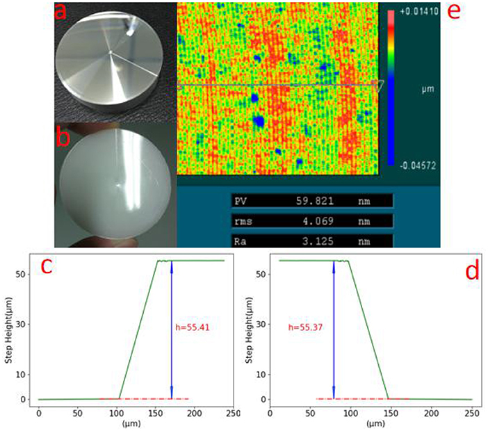
Figure 8. Graph (a) is the picture of the Metal SSM mold; graph (b) is the picture of PE SSM product; graph (c) is the measurement data of step height of the SSM mold, that is about 55.41 um; graph (d) is the measurement data of the step height of the PE SSM, which is about 55.37 um; (e) is the measurement data of the roughness of the PE SSM, which is about 3.1 nm.
Experiment of the Molding Repeatability Test
In order to study the repeatability of the molding process of PE SSM, we used the same molding process parameters and carried out molding experiments. According to the analysis of the difference between the surface step height value between each batch number of molding, the repeatability of this method is estimated, to judge the feasibility of mass production. Due to the limitation of the cost of material and time, 50 molding experiments were carried out. The results in Figure 9 show that the step height of PE SSM is between 55.24 and 55.38 um, the repeatability can reach about 0.25%, and the step height error between PE SSM and the designed value is about 0.58%. We then checked the mold surface after the molding, and there was no significant change before the molding.

Figure 9. Measurement data of step height repeatability experiment.
Conclusion
By developing a process method for the diamond turning and molding technology, we have accomplished a precision process of SSM, which provides an effective means for the bulk-production of SSM. In fact, our experimental results show that there no limit in application to what this technique can achieve. Our process method may be suitable for some other applications, such as a terahertz lens, terahertz beam splitter prism, and a terahertz plane mirror. Moreover, through error compensation of the mold and by optimizing our molding process, the processing precision of PE SSM has potential to be even further improved.
Data Availability Statement
The raw data supporting the conclusions of this article will be made available by the authors, without undue reservation.
Author Contributions
All authors listed have made a substantial, direct and intellectual contribution to the work, and approved it for publication.
Funding
This work was supported by the Natural Science Foundation of China (61775213) and Natural Science Foundation of Chongqing, China (cstc2019jcyj-msxmX0352).
Conflict of Interest
The authors declare that the research was conducted in the absence of any commercial or financial relationships that could be construed as a potential conflict of interest.
References
1. Fan RH, Zhou Y, Ren XP, Peng RW, Jiang SC, Xu DH, et al. Freely tunable broadband polarization rotator for terahertz waves. Adv Mater. (2015) 27:1201–6. doi: 10.1002/adma.201404981
2. Liu C, Wei X, Niu L, Wang K, Yang Z, Liu J. Discrimination of orbital angular momentum modes of the terahertz vortex beam using a diffractive mode transformer. Opt Express. (2016) 24:12534–41. doi: 10.1364/OE.24.012534
3. Sabah C, Roskos HG. Design of a terahertz polarization rotator based on a periodic sequence of chiral-metamaterial and dielectric slabs. Prog Electromagn Res. (2012) 124:301–14. doi: 10.2528/PIER11112605
4. Lu B, Wang H, Shen J, Yang J, Mao H, Xia L, et al. A high extinction ratio THz polarizer fabricated by double-bilayer wire grid structure. AIP Adv. (2016) 6:025215. doi: 10.1063/1.4942515
5. Ma T, Shen YB, Yang GG. Improving diffraction efficiency of DOE in wide waveband application by multilayer micro-structure. Infared Laser Eng. (2008) 37:119–23. doi: 10.3969/j.issn.1007-2276.2008.01.027
6. Kong X, Fu Y, Xia L, Zhang W, Zhang Z, Dong L, et al. Analysis of Ag nanoparticle resist in fabrication of transmission-enhanced subwavelength structures. J Nanophotonics. (2016) 10:046017. doi: 10.1117/1.JNP.10.046017
7. Wang Y, Zhang W, Yang Z, Xiong X, Xia L, Gao M, et al. Fabrication of large area diffractive optical elements by laser direct writing. In: 2016 IEEE International Conference on Manipulation, Manufacturing and Measurement on the Nanoscale (3M-NANO). Chongqing: IEEE (2016).
9. Herzig HP. Micro–Optical Elements, System and Application. Beijing: National Defense Industry Press (2002). 156–8 p.
10. To S, Wang H, Jelenković EV. Enhancement of the machinability of silicon by hydrogen ion implantation for ultra-precision micro-cutting. Int J Mach Tools Manu. (2013) 74:50–5. doi: 10.1016/j.ijmachtools.2013.07.005
11. Ji C, Zhu G, Zhang C, Nam S, Li Q, Xia L. Lenticular-lens-based colored antiglare dashboard surfaces. Adv Mater Technol. (2016) 2:1600177. doi: 10.1002/admt.201600177
12. Zhang SJ, To S, Wang SJ, Zhu ZW. A review of surface roughness generation in ultra-precision machining. Int J Mach Tools Manu. (2015) 91:76–95. doi: 10.1016/j.ijmachtools.2016.01.001
13. Nishio Y, Fujimura K, Ogihara S, Okano M, Kitagawa S. Random micro-lens array illumination device manufactured by ultra-precision machining. SPIE. (2015) 8794:271–350. doi: 10.1117/12.2037486
14. Hao W, Lianhe D, Guodong Z, Dong Z, Weiguo Z. Fabrication of quartz microlens array by using ultra-precision turning mask. Opto-Electron Eng. (2018) 45:170671. doi: 10.12086/oee.2018.170671
Keywords: micron/nano-fabrication, spiral-structure matamaterial, optics, terahertz optics elements, microoptics, ultra-precision fabrication
Citation: Zhang W, Zhu G, Zhu X and Du C (2020) Ultra-Precision Replication Technology for Fabricating Spiral-Structure Metamaterial. Front. Phys. 8:267. doi: 10.3389/fphy.2020.00267
Received: 26 April 2020; Accepted: 15 June 2020;
Published: 28 August 2020.
Edited by:
Xufeng Jing, China Jiliang University, ChinaReviewed by:
Venu Gopal Achanta, Tata Institute of Fundamental Research, IndiaMeina Zhang, Qilu University of Technology, China
Copyright © 2020 Zhang, Zhu, Zhu and Du. This is an open-access article distributed under the terms of the Creative Commons Attribution License (CC BY). The use, distribution or reproduction in other forums is permitted, provided the original author(s) and the copyright owner(s) are credited and that the original publication in this journal is cited, in accordance with accepted academic practice. No use, distribution or reproduction is permitted which does not comply with these terms.
*Correspondence: Chunlei Du, Y2xkdUBjaWdpdC5hYy5jbg==