 Lucas Brely
 Federico Bosia
 Nicola M. Pugno
- 1Department of Physics and “Nanostructured Interfaces and Surfaces” Interdepartmental Centre, Università di Torino, Torino, Italy
- 2Laboratory of Bio-Inspired and Graphene Nanomechanics, Department of Civil, Environmental and Mechanical Engineering, Università di Trento, Trento, Italy
- 3Center for Materials and Microsystems, Fondazione Bruno Kessler, Trento, Italy
- 4School of Engineering and Materials Science, Queen Mary University of London, London, UK
It is known that structural biological materials such as bone or dentin show unprecedented damage tolerance, toughness, and strength. The common feature of these materials is their hierarchical heterogeneous structure, which contributes to increased energy dissipation before failure occurring at different scale levels. These structural properties are the key to achieve superior nanocomposites. Here, we develop a numerical model in order to simulate the mechanisms involved in damage progression and energy dissipation at different size scales in composites, which depend both on the heterogeneity of the material (defects or reinforcements) and on the type of hierarchical structure. Both these aspects have been incorporated into a 2-D model based on a Hierarchical Lattice Spring Model approach, accounting for geometrical non-linearities and including statistically based fracture phenomena. The model has been validated by comparing numerical results to linear elastic fracture mechanics predictions as well as to finite elements simulations, and then employed to study how hierarchical structural aspects influence composite material (mainly 2d, e.g., graphene based) properties, which is the main novel feature of the approach. Results obtained with the numerical code highlight the dependence of stress distributions (and therefore crack propagation) on matrix properties and reinforcement dispersion, geometry, and properties, and how the redistribution of stresses after the failure of sacrificial elements is directly involved in the damage tolerance of the material.
Introduction
Biological materials often display mechanical properties that differ from traditional engineering materials in that they are capable of simultaneously optimizing competing properties, such as stiffness and density or strength and toughness (Gao et al., 2003; Meyers et al., 2008; Giesa et al., 2011; Ritchie, 2011). The optimization mechanisms found in biomaterials can usually be traced back to their internal structure, which includes various characteristic features, principally heterogeneity and a hierarchical arrangement of microstructural and base components (Zhang et al., 2011; Bosia et al., 2012; Meyers et al., 2013). The challenge in recent years has therefore been to fully understand the mechanisms responsible for such outstanding properties and to replicate them in synthetic materials (Munch et al., 2008; Pugno et al., 2012; Wegst et al., 2015). Composite materials already base their lightweight and directional strengthening properties to the combination of materials with considerably different properties, but have yet to achieve the simultaneous strength/toughness or stiffness/density combinations obtained in biocomposites (Ashby et al., 1995). New possibilities for super-composites have emerged with the recent introduction of micro and nano reinforcements like carbon nanotube (CNT) or graphene reinforcements (Coleman et al., 2006; Pugno, 2006; Stankovich et al., 2006; Young et al., 2012). The challenge to further develop new materials with radically improved properties is thus to apply biomimetic strategies to synthetic composite materials (Beese et al., 2014) and where possible to implement complex hierarchical structures (Dimas et al., 2013). To do this, numerical approaches are essential, since there are limited possibilities in experimentally exploring different geometries and structures. Therefore, the formulation of reliable numerical models becomes critical. For models to be predictive, they must be able to capture the main relevant aspects, i.e., heterogeneity, complex geometry, scaling, stress concentrations, damage nucleation and evolution, etc.
In the past, we have developed a so-called hierarchical fiber bundle model (HFBM) with these features, with the main aim of modeling fibrous, essentially 1D materials (Pugno et al., 2008). This code was successfully used to model nanocomposites (Bosia et al., 2010), hierarchical organization (Pugno et al., 2012), and fracture and fatigue of self-healing materials (Bosia et al., 2014, 2015). However, this code is insufficient to model more complex composite geometries where shear effects are not negligible, and a generalization to 2-D or 3-D is necessary. Additionally, a 2-D model would be well suited to the simulation of the mechanical behavior of emerging 2-D material systems such as graphene, e.g., in the evaluation of the influence of the presence and type of defects in crystal structure on the overall mechanical properties, which should be considerable given the crystal bi-dimensional structure (Banhart et al., 2010; Lopez-Polin et al., 2015). A 2-D or 3-D formulation can be achieved by adopting the so-called lattice spring model (LSM) approaches, which have been proposed in the past (Buxton and Balazs, 2002; Alava et al., 2006) and are referred to in various manners in the literature, e.g., “Bonded Particle Model” (Potyondy and Cundall, 2004), “Spring Network Model” (Curtin and Scher, 1990), “Random Spring model” (Nukala et al., 2005), and others. Brittle materials with random failure processes can be modeled by introducing random spatial distributions of springs (Beale and Srolovitz, 1988) and/or fixed or random fracture thresholds for the springs (Alava et al., 2006; Zhao et al., 2011). In order to be used for realistic simulations, spring network models need to be verified for consistency with continuum mechanics through homogenization procedures and/or need to be mapped into standard finite elements (Absi and Prager, 1975; Gusev, 2004). More complex versions of the model exploring complicated lattice energy landscapes (Puglisi and Truskinovsky, 2000) or large deformations (Friesecke and Theil, 2002) have also been investigated. A comprehensive review of Lattice models in micromechanics is given in Ostoja-Starzewski (2002).
Here, we develop and validate a 2-D hierarchical lattice spring model (HLSM), implementing the method in a multiscale scheme, and present preliminary results relative to defective reinforced nanocomposites, elucidating specific mechanisms of damage progressions and crack propagation.
Materials and Methods
To simulate the behavior of heterogeneous and hierarchical complex structures, we adopt and extend a LSM approach based on a 2-D cubic lattice interacting via harmonic springs between nearest and diagonal neighbors, as in Friesecke and Theil (2002). The adopted force–displacement relationship considered here is linear for the sake of simplicity, as discussed below (but this hypothesis can be relaxed). The regular grid consisting of nodes and springs used to discretize the 2-D material portion is shown in Figure 1. As mentioned, spring properties need to be assigned appropriately in order to obtain the equivalence of the strain energy of the elementary cell UCell with that of a continuum UContinuum (Absi and Prager, 1975), i.e., UCell = UContinuum. For 2D plane stress problems, we have:
where V* is the volume of the elementary cell, E* its Young’s modulus, G* its shear modulus, v its Poisson’s coefficient, and εxx,εyy,εxy, are the components of the strain tensor. Using the relation , Eq. (1) becomes:
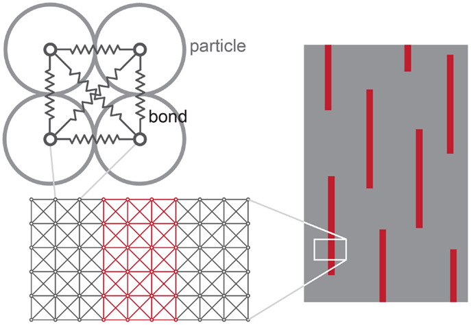
Figure 1. Schematic of the adopted hierarchical lattice spring model (HLSM), illustrating the network of “springs” connecting nodes in which the material is discretized at different size scales. Different mechanical properties assigned to the springs (represented in different colors on the right) correspond to different material portions, e.g., matrix and reinforcements in a composite material (right).
The stored energy of the unit cell of the considered spring network UCell is obtained by taking the sum of the strain contributions of each spring:
where E is Young’s modulus of the springs (taking for simplicity springs with the same stiffness), V the volume of the springs along the main axes and V’ the volume of the diagonal springs. Equating (2) and (3), and considering for simplicity E = E* (but the analysis can be generalized to heterogeneous materials), we have:
These conditions are therefore enforced for the spring network. The condition on Poisson’s ratio of the material is not excessively limiting, since in this study we are interested in discussing general concepts and highlighting qualitative effects, rather than studying specific materials.
As mentioned, linear elastic springs are considered. However, in the considered simulations, non-negligible rotations and/or translations deriving from fracture growth in the modeled material elicit the need for an iterative scheme to avoid large errors in the solution that could be committed in the case of a simple linear analysis. This is due to the occurrence of geometrical non-linearities, due to large displacements and deformations. Therefore, a total Lagrangian formulation is employed, where the governing equations are derived from the Green strain measure (Bathe and Bathe, 1996).
Assuming a quasi-static load case, the equilibrium is based on an iterative procedure to impose the balance between internal (fint) and external (fext) forces using a Newton–Raphson iterative scheme:
with
where ns is the number of springs in the domain, B0 the transformation matrix, Vi the spring volume, F the deformation gradient matrix, E the spring’s Young’s modulus and ε the spring’s strain tensor. Considering the discrete governing equation:
where nn is the number of nodes used for the discretization of the domain, uh the trial solution, N a set of linear trial functions, X the domain undeformed configuration, x the domain deformed configuration, and u the displacement.
Simulations are carried out in displacement control, as proposed in Batoz and Dhatt (1979). Fracture is implemented based on a failure strain criterion on the single springs. At each load step, a spring is removed from the lattice if its maximum strain is exceeded, simulating local failure:
At the smallest considered scale in simulations, ultimate strain values can be assigned deterministically or according to Weibull statistical distributions (Weibull, 1952) to account for material heterogeneity and defectivity occurring at a lower size scale than that considered in the simulation. The cumulative distribution function of a Weibull distribution is given by:
Where k is the shape parameter and λ the scale parameter of the distribution. For example, if the lowest simulation scale is of the order of various nanometers in a CNT-reinforced composite, a Weibull distribution to describe the dispersion in CNT ultimate tensile strain values, accounting for their defectivity, can be estimated from experimental or numerical data from the literature.
To model heterogeneous materials, e.g., composites, different mechanical properties are assigned to the springs (e.g., elastic modulus, ultimate strain) as a function of the material type (typically matrix or reinforcement). Since we are primarily interested in evaluating the role on strength of hierarchical and structural effects, brittle fracture is modeled with a linear elastic behavior up to failure. This also allows a reduction in simulation times with respect to a plastic constitutive law; moreover, plasticity at the crack tip is accounted for thanks to the discrete nature of the model.
As discussed in the introduction, structural biomaterials present a hierarchical structure that often differs from one scale level to another. To model these structures extensively using the LSM approach above would lead to huge computational costs, and therefore a multiscale approach is adopted, i.e., subsystems at different size scales in the considered material are modeled. The mechanical properties of a domain obtained as output from a certain hierarchical level become the input for the hierarchical level above. This is illustrated schematically in Figure 2. The presence of both defects and reinforcements can be modeled at each hierarchical level, which is simulated separately using representative portions of the domain, starting with the smallest scale or level n, supposing that the structure can be modeled with n hierarchical levels. Mechanical properties (i.e., Weibull distribution parameters) at level n-1 are derived from simulations at level n and so on. Given the hierarchical nature of the model, we refer to it as “HLSM.” Although in principle the procedure can be extended to a high number of hierarchical levels, and three are shown in Figure 2, for simplicity in the following only two levels of hierarchy will be considered.
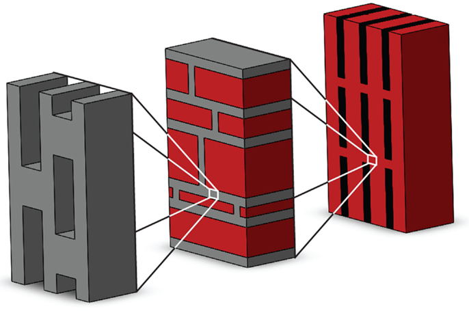
Figure 2. Schematic illustration of an example, of hierarchical multiscale procedure adopted in HLSM simulations. Both defects (or porosity) and reinforcements can be integrated in the model of a material portion at any given size scale, to derive mechanical properties at the hierarchical level above.
Results
Model Validation
The main mechanisms the computational model needs to correctly reproduce at microscale are strain concentrations (e.g., at crack tips), load transfer between the matrix and the reinforcement, fracture nucleation, etc. These aspects are addressed in preliminary validation simulations, where HLSM results are compared to finite element method (FEM) calculations. For the latter, the COMSOL Multiphysics commercial package is used, specifically the Structural Mechanics Module. To validate the developed HLSM code, we consider the strain distributions arising in (a) a laterally cracked representative volume element (RVE) and (b) a RVE with a centrally located reinforcement.
Laterally Cracked RVE
We first consider a pre-cracked RVE subjected to a tensile strain ε0 = 5%, perpendicular to the direction of the crack (X direction), as shown in the schematic in Figure 3. The RVE is constituted by a 200 × 150 regular node grid in the HLSM and the initial crack length l extends to one-third of the RVE width w. A relatively soft material, simulating a polymeric matrix, is considered, with Young’s modulus Em = 1 GPa and Poisson’s ratio νm = 0.3. The same geometry and boundary conditions are considered in FEM simulations, using a 2-D plane strain approximation, a free triangular element mesh refined in the vicinity of the crack tip, and second-order Lagrange elements. HLSM and FEM results are compared in the plot in Figure 3 for the vertical strain YY taken along the line of the crack, in the X direction, with the origin taken as the crack tip. The agreement is very good, showing that the adopted HLSM is capable of simulating correct strain fields in the vicinity of singularities such as crack tips. The small discrepancies can be physically due to the discrete nature of the material and thus can be reduced adopting a finer discretization in the HLSM model. In the plot, we also report the predicted strain profile using quantized fracture mechanics (QFM) (Pugno and Ruoff, 2004), for which in proximity of the crack tip the strain ε varies as:
where a is the fracture quantum, taken as half the discretization length.
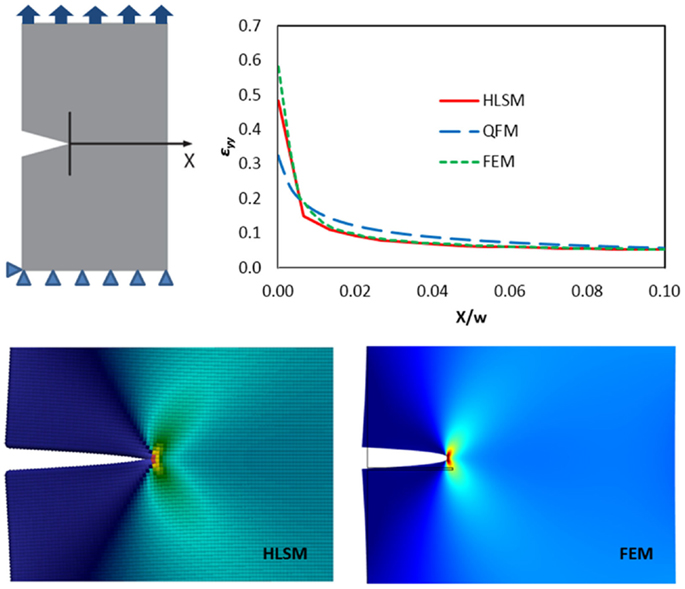
Figure 3. HLSM simulation results for a tensile loading experiment on a laterally cracked RVE (schematic, top left). Vertical strain YY results along the X axis coincide with those from FEM simulations and quantized fracture mechanics (QFM) calculations, shown in the plot (top right). HLSM and FEM simulations also predict the same full-field strain distributions at the crack tip (bottom left and right, respectively).
Also shown in Figure 3 is the overall spatial distribution of strain YY in the pre-cracked RVE. The calculated field, through HLSM and FEM, is consistent with results in the literature (Irwin, 1957) and the associated graph shows the strain concentration near and around the crack tip.
Centrally Reinforced RVE
Reinforcements embedded in a softer matrix behave as stiffeners and take up the strains applied on the surrounding matrix zone. The strain is transferred through the interface between the two materials, which is assumed to be perfect in the present case. The considered RVE is as previously discretized in a 200 by 150 regular node grid, and schematically shown in Figure 4. The reinforcement is chosen as linear elastic, with a stiffness 100 times that of the matrix and a high aspect ratio of 80, to model nanoreinforcements such as CNTs or Graphene nanoplatelets, which can achieve such high slenderness ratios. The applied displacement corresponds to a 5% strain in the length direction of the inclusion (Y axis). The calculated strain distributions along the directions parallel and perpendicular to the reinforcement (Y and X axes, respectively) are shown in the plots in Figure 4, where HLSM results are compared to FEM calculations. The agreement is again very good. The corresponding full-field spatial distribution of strain in the Y-direction around the inclusion is shown in Figure 5. It can be seen that deformations inside the matrix decrease around the linear inclusion inside the “reinforced area.” The level of load transfer from the matrix to the reinforcement is indicative of the efficiency of the reinforced structure. On the other hand, deformations increase around the tips of the reinforcement, and these regions are therefore typically where crack initiate (as can be observed in the inset of Figure 5) and then continue to propagate. These results agree with well-known “shear lag” models (Gao and Li, 2005), and also with experimental data in the literature (Bigoni et al., 2008), and also show the interface debonding that can occur near the crack tip. Consequently, in the case of high aspect ratio inclusions, the presence of reinforcements in the matrix provide a stiffening of the material, but also anticipate fracture nucleation and growth due to the stress concentration at the tips. This illustrates one of the practical aspects of the conflict between strength and toughness in the design of composite structured materials.
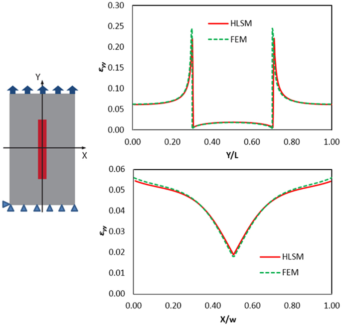
Figure 4. HLSM simulation results for a tensile loading experiment on a centrally reinforced RVE (schematic on the left). Strain YY variation along X and Y axes normalized with respect to width w and length L (bottom right and top right, respectively) compared to that of FEM simulations.
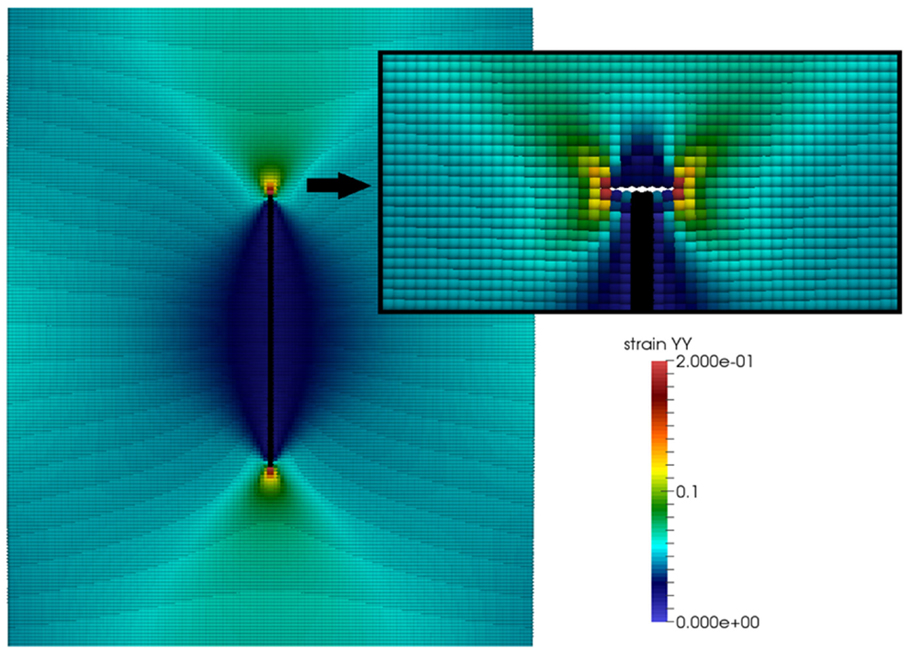
Figure 5. YY Strain field calculated using HLSM model for a vertically loaded RVE with a centrally embedded stiff linear elastic inclusion. The inset highlights the strain concentration at the tips of the reinforcement, giving rise to crack nucleation and propagation.
Simulations
Simulations are first carried out on a model reinforced composite structure to highlight the mechanisms responsible for fracture nucleation and propagation. The considered reinforcements are again much stiffer than the matrix (Ef = 100Em), have a high aspect ratio (l/w = 50), and are distributed homogeneously in a staggered and aligned arrangement parallel to the loading direction, with a volume fraction corresponding to approximately Vf = 6.7%. Figure 6 illustrates the evolution of the simulated damage and crack propagation in such a composite RVE when subjected to tensile loading. Again, strains in the Y direction are represented in color scale. The cracks initiate in regions adjacent to the tips of the reinforcement where initial strain concentrations are maximum (Figure 6A), propagate horizontally, and are stopped when they reach the closest reinforcement (Figure 6B). The load is transferred to the reinforcements through the shear deformation of the matrix, as discussed in Section “Results.” At this point, fracture propagates in the direction of the fibers through shear loading, giving matrix-fiber debonding and thus connecting different cracks originated at the tips (Figure 6C). This leads to the ultimate failure of the composite (Figure 6D). The corresponding stress–strain curves (not shown in this case) display a non-linear behavior which can be assimilated to elasto-plastic behavior deriving from crack nucleation and stopping. Thus, the non-linearity is only structure related, due to the linear elastic behavior assumed here for the material constituents. Similar results have been obtained considering various types of bi-material heterogeneous structures, in bone- or nacre-like (“brick/mortar”) configurations (Sen and Buehler, 2011).
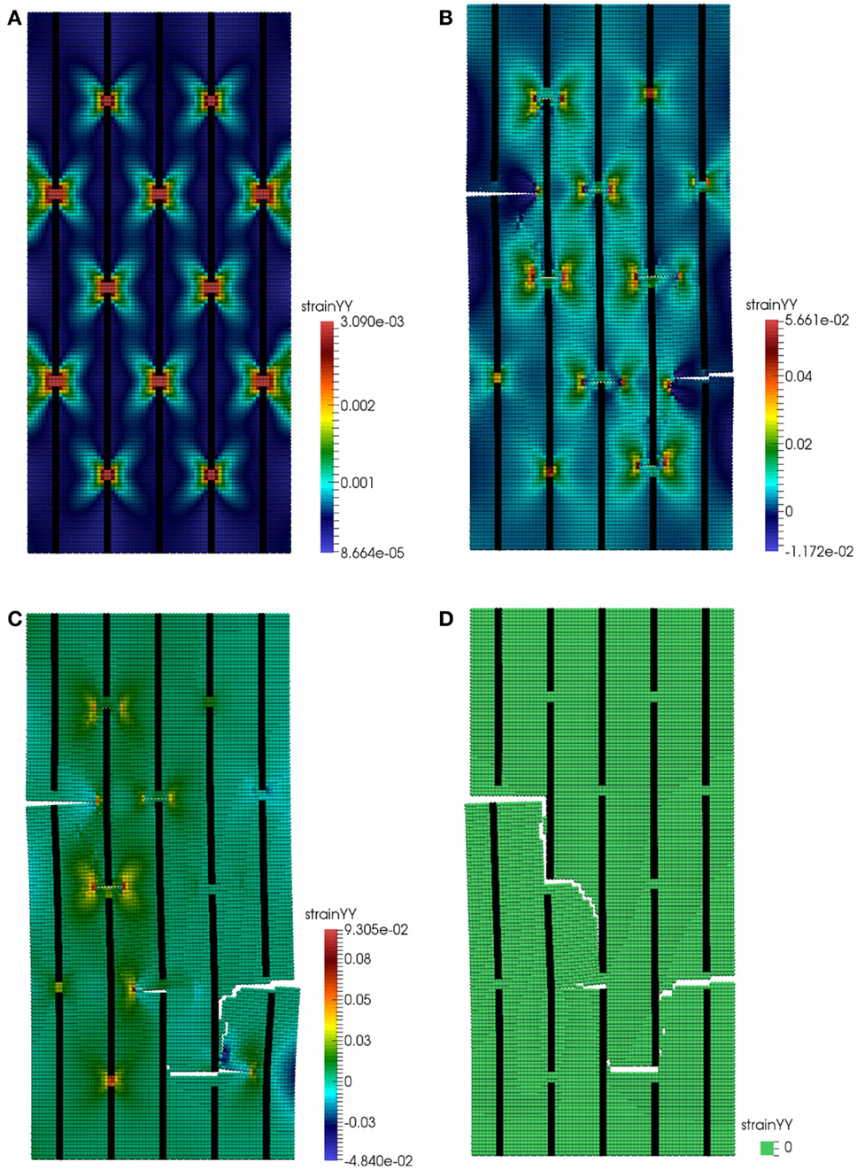
Figure 6. Strain fields during tensile test of the heterogeneous matrix/reinforcement structure. (A) linear elastic part. (B) Tips cracks opening leading to the plastic part. (C) debonding leading to the material failure (D).
Next, the influence of porosity at microscopic level has been evaluated by including varying defect percentages in the simulations, in a multi-scale hierarchical approach. The lower hierarchical scale is used to model a matrix containing different volume fractions of uniformly randomly distributed pores or defects, represented here by a percentage of randomly assigned broken springs. Numerical uniaxial tensile tests are performed on these sub-volumes and the corresponding mechanical properties (stiffness and ultimate strain) are obtained. The resulting properties display some statistical dispersion, given the random distribution of the defects which can differ from one simulation to the next, and are thus fitted using a Weibull distribution, which is widely used in modeling the strength of solids (Weibull, 1952). The scale and shape parameters for the derived stiffness and ultimate strain Weibull distributions then become the input for the single springs in the upper hierarchical level, which includes both matrix and reinforcements. The springs in the reinforcements are chosen as previously 100 times stiffer and stronger than those used for the matrix, and reinforcement dimensions and distributions are the same as for those of simulations in Figure 6. Results for the upper hierarchical level (the “composite” level) are shown in Figure 7 for varying volume fractions of defects in the matrix. The figure illustrates the percentage degradation of stiffness, ultimate strain, strength, and toughness of the resulting composite, normalized with respect to the defect-free material. Simulations predict a toughness reduction of up to 87% and a strength reduction of up to 71% for a 10% defect content, whilst stiffness and ultimate strain reductions are smaller (51 and 27%, respectively) for the same defect volume fraction.
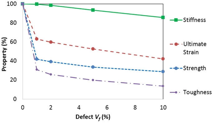
Figure 7. Calculated percentage mechanical property reductions of model composite with increasing defect volume fraction (Vf).
We also study the influence of reinforcement size or shape in the matrix. A single-scale model can be used in this case, and different aspect ratios l/w = 20, 40, 80, 120 for the reinforcements are considered, with the same staggered distribution and material properties as considered previously. Volume fractions of reinforcements between the different cases vary minimally between 5.5% (l/w = 20) and 6.5% (l/w = 120). Results are shown in Figure 8 and demonstrate how increasing aspect ratios lead to a stiffening and strengthening of the composite. Since volume fractions are virtually the same for the various cases, these effects are due to the non-trivial stress distributions occurring in the matrix for increasing aspect ratios and reinforcement overlap, which lead to a more efficient stress transfer from the matrix to the stiffer reinforcements. Such an effect cannot be captured, e.g., by a widely used simple rule of mixtures, and the example illustrates how structure, as well as material constituents, can control the overall mechanical behavior. The toughness of the composite remains approximately constant for varying reinforcement aspect ratios (a 4% decrease for l/w = 120 with respect to l/w = 20). This is because two competing effects are at play: on the one hand, crack path lengths increase for increasing aspect ratios (schematically shown in Figure 8, top), which implies an increase in toughness, on the other hand, the discussed overall material stiffening leads to reduced ultimate strains and a decrease in toughness.
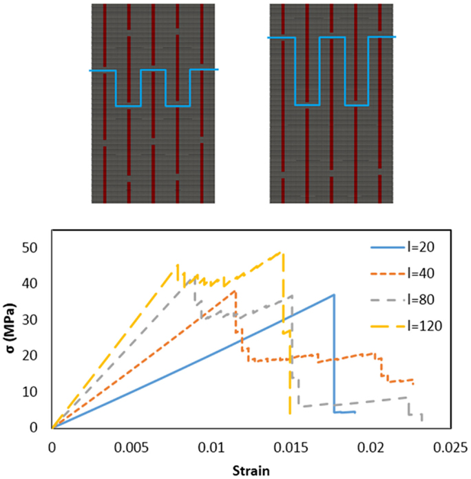
Figure 8. Top: structure of model composites with varying reinforcement aspect ratios (l/w = 40 and l/w = 80), with schematic crack propagation paths. Bottom: corresponding stress–strain curves for varying reinforcement aspect ratios. Increasing aspect ratio leads to increasingly stiff behavior.
To further highlight this effect, a hierarchical structure is now considered. Results from Figure 6 show that in a uniaxially loaded heterogeneous structure the matrix sub-regions are subjected to varying loading conditions of tension/shear, depending on the direction of the reinforcements. Therefore, if we consider a hierarchical composite with multiple scale levels each presenting a specific architecture, it is clear that the overall behavior depends on the direction-dependent response of the structure at the lower scale, which must be derived in different loading conditions and subsequently injected at the next hierarchical level. To illustrate this, we consider a 2-level hierarchical composite constituted by a directionally defected/porous material at the lowest scale, schematically shown in Figure 9, which can appropriately model various systems such as fiber-reinforced foams (Vaikhanski and Nutt, 2003), bioscaffolds (Huang et al., 2013), or the so-called nanolattices or metamaterials (Meza et al., 2014). The hollow structure considered here contains a 20% volume fraction of voids (thus reducing the overall density and increasing the specific stiffness of the matrix, as in Meza et al. (2014), and is composed of overlapping “pores.” Simulations show that the representative RVE for this structure displays an anisotropic response in its stress–strain curves, also shown in Figure 9 (top right). The stiffness and strength as well as toughness of the structure increase with alignment of the load along the direction of the elongated pores, when the beam-like elements are working under tension, as opposed to loading perpendicular to the pores, when the beam-like elements are mainly subjected to bending (as highlighted in Figure 9, bottom).
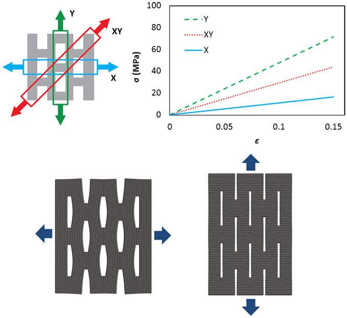
Figure 9. Schematic of the adopted RVE (top left) in a hierarchical multi-scale simulation, and its resulting stress–strain behavior (top right). The element is stiffer and stronger in the longitudinal direction (Y axis) with respect to the transverse direction (X axis), while springs in the diagonal direction (XY) have intermediate properties. The resulting deformation for loading in the X and Y directions is illustrated at the bottom left and right of the figure, respectively.
These results obtained for RVEs at the first hierarchical level are then used as the input of for the second hierarchical level, which is a fiber-matrix structure similar to that considered previously (e.g., in Figure 6). The fibers are again 100 times stiffer and stronger than the matrix material, not considering voids. The fiber aspect ratio is l/w = 50, with a volume fraction of 6.7% and maximal reinforcement overlap. The results reported in Figure 10 highlight the impact of anisotropy at the first hierarchical level on overall properties. In the first case (A), the matrix RVEs are oriented so as to obtain maximal strength in the direction of the fibers. Therefore, crack nucleation at the reinforcement tips requires a higher load level. When the matrix in the tip region fails, debonding directly ensues due to the low strength required to damage the matrix in the fiber direction. It is important to notice that only few cracks have opened during the test, and that the evolution to a traversing crack is direct, leading to a brittle fracture with virtually elastic behavior up to failure. In the second case (B), the low strength of the matrix in the fiber direction leads to the opening of various cracks at reinforcement tips. In this case, a higher load can be transferred between fibers before failure occurs, and the overall stress–strain behavior is therefore elasto-plastic. Maximum strength is obtained for case A, and maximum ultimate strain and toughness for case B.
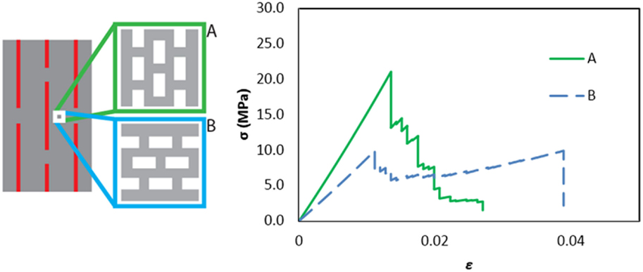
Figure 10. Incorporation of “A” type and “B” type RVEs in the matrix of a reinforced composite in a multi-scale hierarchical scheme. The corresponding stress–strain plots are shown on the right. As expected, “A” type RVEs give rise to a stiffer, stronger composite, while “B” type elements yield a softer, tougher composite.
Despite its simplicity, this case study highlights the complex interaction between structural architectures at different hierarchical levels. Even considering only two levels of hierarchy, it is possible to simulate and design preferential material orientations depending on the type of expected loading, in order to optimize and calibrate the architectures for improved global material response. This becomes more feasible when increasing the number of hierarchical levels (e.g., seven in the case of bone) and the corresponding range of size scales involved, from nano to macro.
Conclusion
Complex hierarchically built composite structures are the way forward to design materials with exceptional or tailor-made mechanical behavior. Designing and realizing these structures is experimentally challenging, and therefore the need for reliable numerical models to characterize and optimize their behavior is acute. In this study, we have presented a novel numerical HLSM to design structural biomaterials and hierarchical nanocomposites, which correctly accounts for defects/porosity and material heterogeneity at different hierarchical levels, and allows the evaluation of the corresponding stress concentrations, crack nucleation, and propagation. As examples, the influence of reinforcement aspect ratios and defect distributions on crack nucleation and propagation inside the matrix have been studied, using a multi-scale approach, in order to model nacre-like composites. Simulations show how structure at lower hierarchical levels affects global properties such as stiffness, ultimate strain, strength, and toughness. Moreover, results show that interaction between these lower level hierarchical properties and macroscopic properties such as the overlapping of the reinforcements in the matrix are key parameters that lead to non-trivial changes in material behavior, e.g., from brittle to ductile. Numerical simulations carried out by Sen and Buehler (2011) show similar results on the behavior of the hierarchical composite structure, i.e., from linear elastic base components, an elasto-plastic stress–strain behavior deriving from crack nucleation and stopping emerges. The additional contribution of the present paper is to further investigate how the composite organization and hierarchical architecture strongly influence the mechanical properties of the material and how it is possible to optimize those using specific criteria, using the same starting matrix/reinforcement materials. This is obtained, for example, by varying the dimension of the reinforcements at a single scale level and considering different orientations in a 2-level hierarchical material.
Thus, the developed HLSM 2-D code has shown reliability in simulating heterogeneity, hierarchy, and fracture propagation inside structured layers, showing promise for the application to more complex hierarchical structures. Thanks to the rapidly developing field of nanocomposite manufacture, it is already possible to artificially create materials with multi-scale hierarchical reinforcements. The developed code could be a valuable support in the design and optimization of these advanced materials, drawing inspiration and going beyond biological materials with exceptional mechanical properties. Further, the model can prove useful in the modeling of 2-D materials such as graphene and graphene-reinforced composites, where defects can play a major role in determining the overall mechanical properties, and their composites. In future works, more complex geometries will be studied by considering 3-dimensional structures and more scale levels (as observed in nature) to further capture optimization aspects in toughening/stiffening strategies in hierarchical materials. Other interesting features that are potentially linked to energy dissipation in biomaterials will also be evaluated, such as non-linear properties of the matrix, non-local bonding, and imperfect matrix/reinforcement interface properties.
Conflict of Interest Statement
The authors declare that the research was conducted in the absence of any commercial or financial relationships that could be construed as a potential conflict of interest.
Acknowledgments
NP is supported by the European Research Council (ERC StG Ideas 2011 BIHSNAM n. 279985 on Bio-Inspired hierarchical supernanomaterials, ERC PoC 2013-1 REPLICA2 n. 619448 on Large-area replication of biological antiadhesive nanosurfaces, ERC PoC 2013-2 KNOTOUGH n. 632277 on Supertough knotted fibers), by the European Commission under the Graphene Flagship (WP10 “Nanocomposites,” n. 604391) and by the Provincia Autonoma di Trento (“Graphene Nanocomposites,” n. S116/2012-242637 and delib. reg. n. 2266). LB and FB acknowledge support from BIHSNAM. Computational resources were provided by HPC@POLITO, a project of Academic Computing within the Department of Control and Computer Engineering at the Politecnico di Torino (http://www.hpc.polito.it), for which we acknowledge the head of the Department, Prof. F. Della Croce.
References
Absi, E., and Prager, W. (1975). A comparison of equivalence and finite element methods. Comput. Methods Appl. Mech. Eng. 6, 59–64. doi: 10.1016/0045-7825(75)90015-8
Alava, M. J., Nukalaz, P. K. V. V., and Zapperi, S. (2006). Statistical models of fracture. Adv. Phys. 55, 349–476. doi:10.1080/00018730300741518
Ashby, M. F., Gibson, L. J., Wegst, U., and Olive, R. (1995). The mechanical-properties of natural materials.1. Material property charts. Proc. R. Soc. Math. Phys. Sci. 450, 123–140. doi:10.1098/rspa.1995.0075
Banhart, F., Kotakoski, J., and Krasheninnikov, A. V. (2010). Structural defects in graphene. ACS Nano 5, 26–41. doi:10.1021/nn102598m
Bathe, K.-J. R., and Bathe, K.-J. R. (1996). Finite Element Procedures. Englewood Cliffs, NJ: Prentice Hall.
Batoz, J.-L., and Dhatt, G. (1979). Incremental displacement algorithms for nonlinear problems. Int. J. Numer. Methods Eng. 14, 1262–1267. doi:10.1002/nme.1620140811
Beale, P. D., and Srolovitz, D. J. (1988). Elastic fracture in random materials. Phys. Rev. B 37, 5500–5507. doi:10.1103/PhysRevB.37.5500
Beese, A. M., An, Z., Sarkar, S., Nathamgari, S. S. P., Espinosa, H. D., and Nguyen, S. T. (2014). Defect-tolerant nanocomposites through bio-inspired stiffness modulation. Adv. Funct. Mater. 24, 2883–2891. doi:10.1002/adfm.201303503
Bigoni, D., Dal Corso, F., and Gei, M. (2008). The stress concentration near a rigid line inclusion in a prestressed, elastic material. Part II. Implications on shear band nucleation, growth and energy release rate. J. Mech. Phys. Solids 56, 839–857. doi:10.1016/j.jmps.2007.07.003
Bosia, F., Abdalrahman, T., and Pugno, N. M. (2012). Investigating the role of hierarchy on the strength of composite materials: evidence of a crucial synergy between hierarchy and material mixing. Nanoscale 4, 1200–1207. doi:10.1039/c2nr11664b
Bosia, F., Abdalrahman, T., and Pugno, N. M. (2014). Self-healing of hierarchical materials. Langmuir 30, 1123–1133. doi:10.1021/la403497z
Bosia, F., Buehler, M. J., and Pugno, N. M. (2010). Hierarchical simulations for the design of supertough nanofibers inspired by spider silk. Phys. Rev. E Stat. Nonlin. Soft Matter Phys. 82, 056103. doi:10.1103/PhysRevE.82.056103
Bosia, F., Merlino, M., and Pugno, N. M. (2015). Fatigue of self-healing hierarchical soft nanomaterials: the case study of the tendon in sportsmen. J. Mater. Res. 30, 2–9. doi:10.1557/jmr.2014.335
Buxton, G. A., and Balazs, A. C. (2002). Lattice spring model of filled polymers and nanocomposites. J. Chem. Phys. 117, 7649–7658. doi:10.1063/1.1509447
Coleman, J. N., Khan, U., Blau, W. J., and Gun’ko, Y. K. (2006). Small but strong: a review of the mechanical properties of carbon nanotube-polymer composites. Carbon N. Y. 44, 1624–1652. doi:10.1016/j.carbon.2006.02.038
Curtin, W. A., and Scher, H. (1990). Brittle-fracture in disordered materials – a spring network model. J. Mater. Res. 5, 535–553. doi:10.1557/JMR.1990.0535
Dimas, L. S., Bratzel, G. H., Eylon, I., and Buehler, M. J. (2013). Tough composites inspired by mineralized natural materials: computation, 3D printing, and testing. Adv. Funct. Mater. 23, 4629–4638. doi:10.1002/adfm.201300215
Friesecke, G., and Theil, F. (2002). Validity and failure of the Cauchy-Born hypothesis in a two-dimensional mass-spring lattice. J. Nonlinear Sci. 12, 445–478. doi:10.1007/s00332-002-0495-z
Gao, H. J., Ji, B. H., Jager, I. L., Arzt, E., and Fratzl, P. (2003). Materials become insensitive to flaws at nanoscale: lessons from nature. Proc. Natl. Acad. Sci. U.S.A. 100, 5597–5600. doi:10.1073/pnas.0631609100
Gao, X. L., and Li, K. (2005). A shear-lag model for carbon nanotube-reinforced polymer composites. Int. J. Solids Struct. 42, 1649–1667. doi:10.1016/j.ijsolstr.2004.08.020
Giesa, T., Arslan, M., Pugno, N. M., and Buehler, M. J. (2011). Nanoconfinement of spider silk fibrils begets superior strength, extensibility, and toughness. Nano Lett. 11, 5038–5046. doi:10.1021/nl203108t
Gusev, A. A. (2004). Finite element mapping for spring network representations of the mechanics of solids. Phys. Rev. Lett. 93, 034302. doi:10.1103/PhysRevLett.93.034302
Huang, S. P., Li, Z. Y., Chen, Z., Chen, Q., and Pugno, N. (2013). Study on the elastic-plastic behavior of a porous hierarchical bioscaffold used for bone regeneration. Mater. Lett. 112, 43–46. doi:10.1016/j.matlet.2013.08.114
Irwin, G. R. (1957). Analysis of stresses and strains near the end of cracking traversing a plate. J. Appl. Mech. 24, 361–364.
Lopez-Polin, G., Gomez-Navarro, C., Parente, V., Guinea, F., Katsnelson, M. I., Perez-Murano, F., et al. (2015). Increasing the elastic modulus of graphene by controlled defect creation. Nat. Phys. 11, 26–31. doi:10.1038/nphys3183
Meyers, M. A., Chen, P. Y., Lin, A. Y. M., and Seki, Y. (2008). Biological materials: structure and mechanical properties. Prog. Mater. Sci. 53, 1–206. doi:10.1016/j.pmatsci.2007.05.002
Meyers, M. A., Mckittrick, J., and Chen, P. Y. (2013). Structural biological materials: critical mechanics-materials connections. Science 339, 773–779. doi:10.1126/science.1220854
Meza, L. R., Das, S., and Greer, J. R. (2014). Strong, lightweight, and recoverable three-dimensional ceramic nanolattices. Science 345, 1322–1326. doi:10.1126/science.1255908
Munch, E., Launey, M. E., Alsem, D. H., Saiz, E., Tomsia, A. P., and Ritchie, R. O. (2008). Tough, bio-inspired hybrid materials. Science 322, 1516–1520. doi:10.1126/science.1164865
Nukala, P. K., Zapperi, S., and Simunovic, S. (2005). Statistical properties of fracture in a random spring model. Phys. Rev. E Stat. Nonlin. Soft Matter Phys. 71, 066106. doi:10.1103/PhysRevE.71.066106
Ostoja-Starzewski, M. (2002). Lattice models in micromechanics. Appl. Mech. Rev. 55, 35–60. doi:10.1115/1.1432990
Potyondy, D. O., and Cundall, P. A. (2004). A bonded-particle model for rock. Int. J. Rock Mech. Min. Sci. 41, 1329–1364. doi:10.1016/j.ijrmms.2004.09.011
Puglisi, G., and Truskinovsky, L. (2000). Mechanics of a discrete chain with bi-stable elements. J. Mech. Phys. Solids 48, 1–27. doi:10.1016/S0022-5096(99)00006-X
Pugno, N. M. (2006). Mimicking nacre with super-nanotubes for producing optimized super-composites. Nanotechnology 17, 5480–5484. doi:10.1088/0957-4484/17/21/031
Pugno, N. M., Bosia, F., and Abdalrahman, T. (2012). Hierarchical fiber bundle model to investigate the complex architectures of biological materials. Phys. Rev. E Stat. Nonlin. Soft Matter Phys. 85, 011903. doi:10.1103/PhysRevE.85.011903
Pugno, N. M., Bosia, F., and Carpinteri, A. (2008). Multiscale stochastic simulations for tensile testing of nanotube-based macroscopic cables. Small 4, 1044–1052. doi:10.1002/smll.200800062
Pugno, N. M., and Ruoff, R. S. (2004). Quantized fracture mechanics. Philos. Mag. 84, 2829–2845. doi:10.1016/j.msec.2012.12.058
Ritchie, R. O. (2011). The conflicts between strength and toughness. Nat. Mater. 10, 817–822. doi:10.1038/nmat3115
Sen, D., and Buehler, M. J. (2011). Structural hierarchies define toughness and defect-tolerance despite simple and mechanically inferior brittle building blocks. Sci. Rep. 1, 25. doi:10.1038/srep00035
Stankovich, S., Dikin, D. A., Dommett, G. H. B., Kohlhaas, K. M., Zimney, E. J., Stach, E. A., et al. (2006). Graphene-based composite materials. Nature 442, 282–286. doi:10.1038/nature04969
Vaikhanski, L., and Nutt, S. R. (2003). Fiber-reinforced composite foam from expandable PVC microspheres. Compos. Part A Appl. Sci. Manuf. 34, 1245–1253. doi:10.1016/S1359-835X(03)00255-0
Wegst, U. G. K., Bai, H., Saiz, E., Tomsia, A. P., and Ritchie, R. O. (2015). Bioinspired structural materials. Nat. Mater. 14, 23–36. doi:10.1038/nmat4089
Weibull, W. (1952). A statistical distribution function of wide applicability. J. Appl. Mech. 18, 293–297.
Young, R. J., Kinloch, I. A., Gong, L., and Novoselov, K. S. (2012). The mechanics of graphene nanocomposites: a review. Compos. Sci. Technol. 72, 1459–1476. doi:10.1016/j.compscitech.2012.05.005
Zhang, Z. Q., Zhang, Y. W., and Gao, H. J. (2011). On optimal hierarchy of load-bearing biological materials. Proc. R. Soc. B Biol. Sci. 278, 519–525. doi:10.1098/rspb.2010.1093
Keywords: hierarchical lattice spring model, numerical modeling, fracture mechanics, composite materials, hierarchy
Citation: Brely L, Bosia F and Pugno NM (2015) A hierarchical lattice spring model to simulate the mechanics of 2-D materials-based composites. Front. Mater. 2:51. doi: 10.3389/fmats.2015.00051
Received: 28 February 2015; Accepted: 11 June 2015;
Published: 06 July 2015
Edited by:
Giuseppe Saccomandi, Università di Perugia, ItalyReviewed by:
Vincent Legrand, Institut de Recherche en Génie Civil et Mécanique, FranceAnna Marina Pandolfi, Politecnico di Milano, Italy
Copyright: © 2015 Brely, Bosia and Pugno. This is an open-access article distributed under the terms of the Creative Commons Attribution License (CC BY). The use, distribution or reproduction in other forums is permitted, provided the original author(s) or licensor are credited and that the original publication in this journal is cited, in accordance with accepted academic practice. No use, distribution or reproduction is permitted which does not comply with these terms.
*Correspondence: Nicola M. Pugno, Dipartimento di Ingegneria Civile, Ambientale e Meccanica, Università di Trento, via Mesiano, 77, 38123 Trento, Italy,bmljb2xhLnB1Z25vQHVuaXRuLml0