 Vincenzo La Salandra
 Moritz Wenzel
 Oreste S. Bursi
 Giorgio Carta2
- 1Department of Civil, Environmental and Mechanical Engineering, University of Trento, Trento, Italy
- 2Department of Maritime and Mechanical Engineering, Liverpool John Moores University, Liverpool, United Kingdom
- 3Department of Mathematical Sciences, University of Liverpool, Liverpool, United Kingdom
Fluid-filled tanks in tank farms of industrial plants can experience severe damage and trigger cascading effects in neighboring tanks due to large vibrations induced by strong earthquakes. In order to reduce these tank vibrations, we have explored an innovative type of foundation based on metamaterial concepts. Metamaterials are generally regarded as manmade structures that exhibit unusual responses not readily observed in natural materials. If properly designed, they are able to stop or attenuate wave propagation. Recent studies have shown that if locally resonant structures are periodically placed in a matrix material, the resulting metamaterial forms a phononic lattice that creates a stop band able to forbid elastic wave propagation within a selected band gap frequency range. Conventional phononic lattice structures need huge unit cells for low-frequency vibration shielding, while locally resonant metamaterials can rely on lattice constants much smaller than the longitudinal wavelengths of propagating waves. Along this line, we have investigated 3D structured foundations with effective attenuation zones conceived as vibration isolation systems for storage tanks. In particular, the three-component periodic foundation cell has been developed using two common construction materials, namely concrete and rubber. Relevant frequency band gaps, computed using the Floquet–Bloch theorem, have been found to be wide and in the low-frequency region. Based on the designed unit cell, a finite foundation has been conceived, checked under static loads and numerically tested on its wave attenuation properties. Then, by means of a parametric study we found a favorable correlation between the shear stiffness of foundation walls and wave attenuation. On this basis, to show the potential improvements of this foundation, we investigated an optimized design by means of analytical models and numerical analyses. In addition, we investigated the influence of cracks in the matrix material on the elastic wave propagation, and by comparing the dispersion curves of the cracked and uncracked materials we found that small cracks have a negligible influence on dispersive properties. Finally, harmonic analysis results displayed that the conceived smart foundations can effectively isolate storage tanks.
Introduction
In 1999, the Izmit earthquake damaged the largest Turkish petrochemical plant and set it on fire. The fire took five and a half days to extinguish and almost spread to other industrial sites (Barka, 1999). Such events can be described as natural technological events or NaTech events. It is of critical importance for the community and the environment to prevent such incidents from happening. Fuel storage tanks in petrochemical plants need to be regarded as high risk structures, due to their fragility to earthquakes and their potential for cascading effects (Fabbrocino et al., 2005). Their low impulsive frequencies can fall within the excitation frequencies of earthquakes and significant effort is required to isolate them against seismic vibrations. A very innovative solution for isolating tanks at low frequencies is constructing a foundation based on phononic crystals. These crystals can create stop bands, which stop waves from propagating in certain frequency regions (Sigalas et al., 2005). Various applications could benefit from these properties, for example, noise protection (Liu et al., 2000), seismic isolation (Shi and Huang, 2013), or coastal protection (Ha et al., 2002). The present work is dedicated to the feasibility of such metamaterial-based structures for the seismic isolation of fuel storage tanks.
Three- and two-component new foundations were conceived by Cheng and Zhifei (2013). A two-dimensional (2D) array of steel cylinders coated with rubber and embedded in a reinforced concrete matrix constituted the three-component foundation. Conversely, the two-component design was based on the same geometry, but replacing the steel cylinders inside the rubber with homogeneous rubber inclusions. By comparing these two designs, they showed that a three-component periodic foundation can generate useful band gaps for seismic vibration isolation. Furthermore, they concluded that the reinforcement of the concrete matrix has a negligible influence on the band gaps. However, it is important to underline the 2D nature of their proposed designs, which would have to be improved for an omnidirectional wave. Another 2D approach was studied by Gaofeng and Zhifei (2010), while a three-dimensional (3D) approach for a phononic crystal-based structure was proposed by Cheng et al. (2013). The latter design showed the possibility for a 3D foundation to generate stop bands in the low frequency region. Furthermore, they carried out a parametric study on the structural components and their influence on the band gaps. The mass of the resonator core, the thickness of the rubber coating as well as the stiffness of the rubber have proven to be of special importance for the frequency range of the stop bands. In order to validate the effects of stop bands in periodic structures Yan et al. (2014) conducted field experiments on scaled 2D periodic foundations. The comparison between experimental outcomes and numerical results showed that periodic foundations are able to mitigate seismic waves. Furthermore, they found good agreement between experimental tests and dispersion analysis. The work by Achaoui et al. (2016) provides additional insight on filtering waves propagating through a foundation made of inertial resonators. The recent work by Carta et al. (2016) has addressed the suppression of vibrations in fuel tanks via specially tuned systems of many multiscale resonators attached to the tanks.
In the present article, we introduce a smart foundation based on metamaterial concepts that can both attenuate seismic waves and withstand static loads. More precisely, the foundation is capable of attenuating waves in targeted frequency ranges. In our analyses, we are particularly interested in the influence that both geometrical and mechanical properties of a foundation inspired by phononic crystals can have on its dynamic performance as well as its capabilities of bearing gravity loads. In fact, for its practical use, it is of outmost importance to design a foundation that can both attenuate seismic waves and withstand static loads relevant to the coupled structure. Therefore, a broad fuel storage tank, which poses a significant threat to the community and the environment, was considered as a case study for the present design. The materials employed in the foundation are concrete and construction grade silicon, which are commonly used in construction industry. With regard to the design process of the foundation, an iterative procedure was employed. Given the critical frequency region of seismic vibrations for the structure of interest, a unit cell is designed with the aid of a frequency dispersion analysis to cover critical frequencies by means of a stop band. Then, a finite lattice structure is extracted from the infinite lattice of unit cells and is checked on its static behavior at the ultimate limit state (EN 1990, 2004). Furthermore, the coupled (foundation + structure) system is numerically tested on its wave attenuation properties. Since the proposed smart foundation was still excessive in size, we also investigated an optimized design endowed with improved performance and reduced dimensions. Therefore, an analytical study was performed to derive the wave propagation properties of the design, while numerical simulations assessed its performance. Although the proposed design is still in an early research stage, it already shows a great potential in optimizing such a foundation.
As pointed out by Carta et al. (2014) in the analysis of the dynamic behavior of strongly damaged beams, cracks due to static loading can exert marked effects on band gap formation. For this reason, the influence of cracks on the dynamic properties of the proposed foundation is also investigated. Finally, Section “Discussion” discusses main results, draws conclusion and future perspectives.
Materials and Methods
Modal Analysis of a Broad Tank
From a dynamic viewpoint, broad tanks like the one under study can be thought of being composed of an impulsive mass that vibrates in phase with the tank walls at a higher frequency (e.g., 3–5 Hz) and a sloshing mass that vibrates not in phase with the tank walls at a lower frequency (i.e., about 0.3 Hz) (Malhotra et al., 2000). The relevant eigenvalue analysis was carried out with the FE software Comsol Multiphysics (version 5.2). The smart foundation under study is conceived for the higher frequency, since sloshing frequencies can be easily suppressed or mitigated with baffles (Belakroum et al., 2010). Therefore, the design of the unit cell focused on the first impulsive frequency of the fully filled tank, i.e., 4.05 Hz. In fact, this is the eigenfrequency with the largest participant mass in the radial direction. A horizontal excitation at this frequency results in both the largest stresses and accelerations in the tank walls, and thus governs the requirements for the seismic resilience. After disregarding sloshing frequencies, it was possible to model the liquid as an acoustic medium (Ding and Chen, 2001; Carta et al., 2016). This approach significantly reduced the computational cost of the model. As a result, in all forthcoming analyses the liquid inside the tank is assumed to have the same properties as water. The tank itself has a cylindrical shape with a radius, height, liquid height, and wall thickness of 24 m, 16 m, 15 m, and 20 mm, respectively. A steel plate with a thickness of 50 mm was used as bottom plate. In order to simulate the traditional foundation system, the whole tank was set on a 1 m thick concrete slab, as depicted in Figure 1A. Moreover, a damping ratio of 5% was imposed at both 3 and 5 Hz by means of proportional Rayleigh damping on all FE models to hand (Liu and Gorman, 1995). Moreover, an additional modal analysis has been carried out to determine the modal frequencies of the coupled (tank + smart foundation) system. The geometry of the proposed smart foundation is presented in Section “Results” and is shown in Figure 1B. In order to further improve the foundation performance in terms of geometry and dynamic properties, we conceived and analyzed a new unit cell. The optimized design was modeled by means of shell and beam elements and the assembly is depicted in Figure 1C. The relevant cell dimensions are shown in Figure 3A in Section “Analytical Model of the Optimized Design,” respectively.
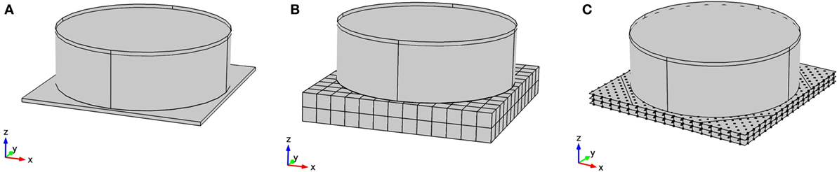
Figure 1. (A) Broad tank on a standard foundation, (B) broad tank on a smart foundation, and (C) broad tank on a smart foundation with optimized unit cells.
Since the fluid level height is not a constant parameter in a storage tank, the impulsive frequency of the structure changes accordingly. Thus, the variable fluid level results in a frequency region, which is considered governing the foundation design. Clearly, we take into account that the varying fluid level height will change the eigenfrequencies of the coupled foundation-tank system.
Floquet–Bloch Theorem and Brillouin Zone
Periodic structures can be designed in order to suppress the propagation of seismic waves in a certain frequency regions. These regions are called band gaps and can be determined with the Floquet–Bloch theorem (Phani et al., 2006). This theorem reduces the study to an infinite lattice of unit cells to the analysis of a single unit cell with Floquet–Bloch quasiperiodicity conditions. After imposing these conditions, a frequency dispersion analysis can be carried out and the band gaps of the unit cell can be found as shown in Figure 5B. In order to obtain the frequency dispersion diagram, we consider the equation of motion for an elastic medium in an Eulerian description,
where the stress–strain relationship reads,
In particular, Fi (i = 1, 2, 3) are the components of the body force, ρ the mass density, u(x) displacement vector, μ(x) and λ(x) Lamè constants, x position vector and δij the Kronecker delta function, respectively. Time t has been omitted for brevity. According to the Floquet–Bloch theorem the solution u(x,t) for a periodic system can be expressed as:
where q = [qx,qy,qz]T represents the wave vector in Eq. 3, while ω denotes the corresponding frequency in rad/s. As a consequence,
with R being the lattice vector. By imposing these boundary conditions on a system and solving the discrete eigenvalue problem of a typical cell, which takes on the following form:
it becomes possible to calculate the frequency dispersion curves. In Eq. 5, K and M are the stiffness and mass matrix, respectively. The wave vector q can be expressed in the reciprocal lattice. Due to the periodicity of the direct as well as the reciprocal lattice, it is possible to reduce the wave space to the first Brillouin zone (Brillouin, 1953). Therefore, in order to find the desired band gaps of the frequency dispersion diagram, it is sufficient to calculate q along the boundaries of this irreducible Brillouin zone (Kittel, 1962). For clarity, the Brillouin zone for the unit cell considered is depicted in the bottom left of Figure 5A, where qx, and qy assume values between 0 and bz, while remaining on the contour of the Brillouin zone.
Static Analysis
For the unit cell to work properly as an element of the foundation, it is necessary to build a static system from the infinite lattice of unit cells. A two-layered grid of unit cells was chosen as a starting point for the foundation. Due to the cubical shape of the cells, it is easy to conceive a framework of walls and slabs suited for the derivation of the static loads. The dispersion analysis of the unit cell resulted in a 4 × 4 m cube with an outer wall thickness of 10 cm, as shown in Section “Unit Cell Design of the Original Smart Foundation.” When these cells are set adjacent to each other, the outer walls can be combined as a rectangular grid with a wall thickness of 20 cm and a spacing of 4 m. The same holds true for the slab between the two layers of unit cells, which results in a thickness of 20 cm for the intermediate slab, while the static analysis resulted in a slab thickness of 35 cm for the top slab. Figure 2 shows the conception of the static system and its dimensions. Details of the foundation are shown in the bottom right of Figure 2A, where the increased top slab and the soil–structure interface are represented. For the present work, the soil was assumed to be bedrock, which allows the foundation to be sustained by line supports along the walls. Since the compression of the rubber, due to static loading, could influence the dynamic behavior of the system, the inner concrete cubes and the rubber coatings were considered as dead loads.
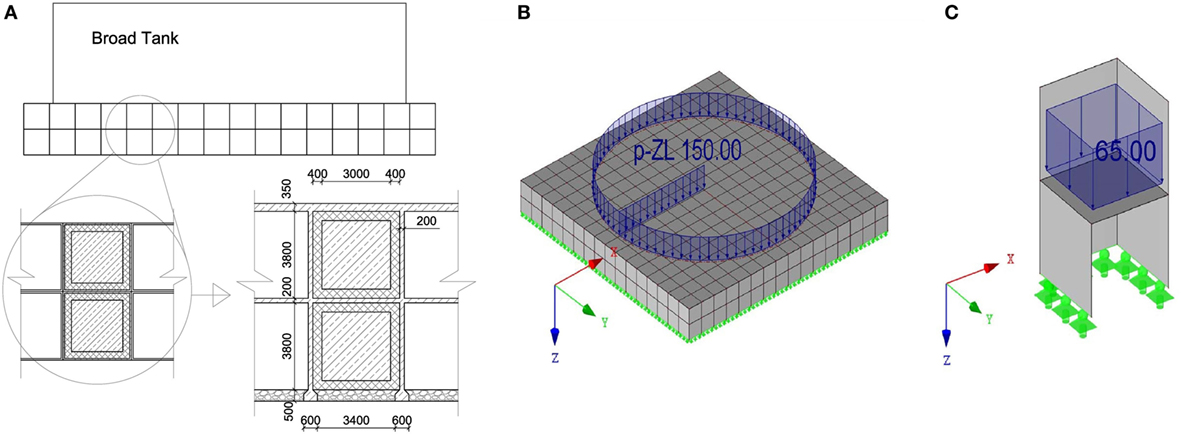
Figure 2. (A) Conception of a static system (dimensions in mm); (B) FE model of the foundation including the tank weight as a surface load (kN/m2); and (C) two unit cells on line supports including the weights of the rubber and inner concrete cubes as surface loads (kN/m2).
A sketch of the FE model of the static system is shown in both Figures 2B,C. The calculation of both stresses and governing forces has been carried out with the FE software RFEM. All walls and slabs were modeled as shell elements with rigid connections to each other. The supports were modeled as simple line supports along the bottom edges of the walls. Once the static system was established, the loads of the tank, rubber and inner cubes were applied. The liquid was assumed to have the same density as water with a maximum liquid level of 15 m. The tank was modeled as a simple face load of 150 kN/m2 and imposed on the foundation. A similar approach was chosen for the rubber and the inner concrete cubes. The weight of both the rubber and inner cubes corresponded to a total gravitational force of 1,040 kN per cell. This force was then spread evenly across the slab between the layers of unit cells, which resulted in a face load of 65 kN/m2. In order to comply with EN 1990 (2004) requirements for the ultimate limit state of the foundation, all dead loads (including gravitational forces of walls and slabs) were multiplied by the partial load safety coefficient γG = 1.35. Finally, all dimensions and steel reinforcements were checked according to the EN 1992-1-1 (2003). Shear walls were verified for their compressive strength, while the slabs were reinforced with steel rebars.
With reference to the optimized unit cell design depicted in Figure 3A, dimensions have been significantly reduced with respect to the original design. In particular, line moments decreased with the reduction of the span width by the power of two and the new slabs 200 mm thick suffice the EN 1992-1-1 (2003) requirements. The columns of the optimized design need to be checked for their compressive strength. The relevant checks are presented in Section “Static Analysis.”
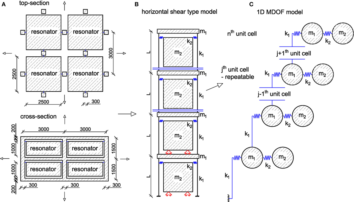
Figure 3. (A) Top-section and cross-section of the optimized foundation; (B) simplified model for shear-wave propagation; and (C) 1D mass-resonator chain model.
Materials
The first proposed model for the foundation consists of three components: the concrete resonator cubes, the rubber coatings, and the reinforced concrete framework. For the concrete parts the strength grade was assumed to be C30/37 in agreement with EN 1992-1-1 (2003), while the rubber was assumed to be construction grade silicon. Fuel storage tanks are commonly made of welded construction steel. For all FE models, the materials were considered homogeneous and linear elastic, and their main mechanical properties are collected in Table 1. The design of the optimized solution uses the same concrete as the original one, but replaces the rubber with steel springs as indicated in Figure 3B. The spring stiffness k2 has been tuned to provide a band gap with a lower bound at 2.4 Hz as discussed in Section “Modal Analysis of a Coupled Broad-Tank-Foundation System.” It was found that k2 = 3.7 MN/m.
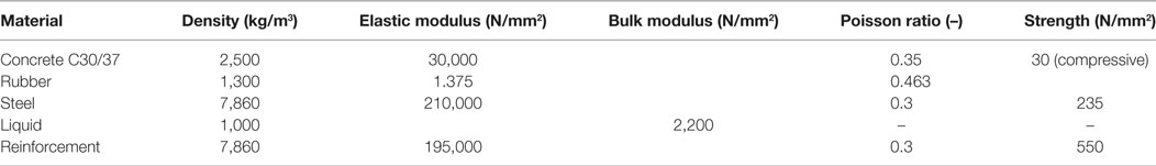
Table 1. Mechanical properties of materials.
Functionality Evaluation of the Original Design
Due to the finite dimensions of the original foundation and the necessary redesign for its static behavior, the foundation can no longer be treated as an infinite lattice of perfectly equal unit cells. In order to determine the wave propagation properties, it is crucial to carry out additional computations, since the appearance of a stop-band in a finite structure is unrealistic. However, an attenuation zone is expected to appear in the frequency region of the predicted stop-band. In order to understand the behavior of the finite structure, two models are investigated: (i) the first model of the foundation does not include the tank and (ii) the second one contains the complete system, including the tank and the fluid inside. The optimized design was carried out similarly and is described in Section “Optimization of the Unit Cell.”
A horizontal harmonic acceleration was imposed at the bottom of the foundation. When comparing the response of the top of the foundation to the imposed wave, it becomes possible to show the effectiveness of the attenuation at a certain frequency. This results in a frequency response function of the type shown in Figure 8. The analysis was then carried out for a foundation with one, two, and three layers. Furthermore, the foundation has also been analyzed with a thinner concrete wall thickness, in order to see whether the horizontal stiffness of the structure has an influence on the attenuation behavior.
The FE model of the complete system, including foundation, tank and liquid as an acoustic medium, has 531684 DoFs. In order to minimize the computational effort due to the transient nature of seismic waves, all calculations were carried out in the frequency domain; accordingly, the steady-state response of the coupled system was checked for the frequencies of interest. In order to show the effectiveness of the attenuation, the steady state response of the broad tank on a traditional concrete slab foundation was compared to that of the tank sitting on the smart foundation. In particular, maximum accelerations of the uncoupled/coupled system were considered to be of special interest, since they correlate with the highest stresses appearing in the system.
Optimization of the Unit Cell
In order to reduce the foundation’s size while maintaining its performance, the foundation was redesigned according to the results obtained in the Section “Functionality Evaluation.” We found that: (i) the shear stiffness plays an important role for the effectiveness of the foundation, see Figure 8 and (ii) the rubber, due to its fixed elastic modulus, constrains our design in terms of variability of the band gap. The two main advantages of the redesign are the reduction in stiffness, by replacing the walls with columns, and attaching the resonators to the columns with steel springs instead of rubber as indicated in Figure 3B. As evident from Figure 8, the reduction of stiffness leads to a more pronounced attenuation zone, while the steel springs provide the option of tuning the boundaries of the unit cell’s band gap. As a result, see Figure 3A, the new dimensions of the unit cell are 3 m × 3 m × 1.5 m, 0.3 m × 0.3 m column thickness, 0.2 m slab thickness and 2.5 m × 2.5 m × 1 m resonator size. Note that due to the reduction of the overall stiffness of the coupled system, the first impulsive frequency observed, decreased to 2.4 Hz, see Table 2, and, therefore, a band gap has to be tuned to this lower frequency. Furthermore, we assumed that the resonators move on a frictionless surface in the horizontal direction. This is a necessary assumption in order to keep the calculations linear for the frequency domain analysis.
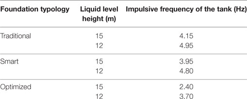
Table 2. First impulsive eigenfrequencies of broad-tank-foundation systems with various liquid heights.
The functionality evaluation of the optimized design followed the same steps presented in Section “Functionality Evaluation of the Original Design.” However, in contrast to the model of the original design, the optimized cell variant was discretized with beam and shell elements, which further reduced the computational effort.
Analytical Model of the Optimized Design
In order to investigate the metamaterial-like properties of the new design, we conceived an analytical model of the foundation and calculated both the frequency response and the dispersion analysis of unit cells. The main dimensions of the unit cell, the horizontal shear model and the 1D MDoF system are depicted in Figures 3A–C, respectively. This model allows only shear type waves that act in the horizontal and propagate in the vertical direction.
As can be seen in Figure 3C, the jth unit cell can be repeated in order to achieve as many layers as desired. The equations of motion read,
where m1 denotes the mass of a slab between two layers of foundation including half the columns of the layer below and half the columns of the layer above; m2 denotes the mass of the resonator; k1 denotes the horizontal stiffness of two columns, which represents the equivalent stiffness of the columns pertaining to each resonator; k2 represents the equivalent stiffness of the steel springs holding the resonator; and u describes the horizontal displacement. In order to relate the state variables across the system, the equations of motion must contain the displacement of the j − 1th and j + 1th unit cell. Therefore, u is endowed with a subscript (1, 2) that describes the corresponding mass, while the unit cell is determined by the superscript (j − 1, j, j + 1). For a finite system these equations can be written in matrix form. The generalized stiffness and mass matrix for a system with n unit cells reads,
The relevant dispersion relation of the system can be found by imposing the Floquet–Bloch boundary conditions (4) on the Eqs. 6 and 7, imposing a time-harmonic solution and looking for non-trivial solutions. The dispersion relation is given by:
A similar solution has been found by (Huang et al., 2009), who analyzed the negative effective mass effect in an acoustic metamaterial. Here, ω denotes the circular frequency; L the length of the column or height of one layer; and q the wave number with dimension 1/m. The values for m1, m2, k1, k2, and L are 5,850 kg, 15,625 kg, 12e7 N/m, 3.6e6 N/m, and 1.5 m, respectively.
In order to compare the results provided by the numerical models, also quantitatively, damping ratios of 1, 3, and 5% were imposed to 3 and 5 Hz by means of a Rayleigh model. Furthermore, a model with 1, 2, and 3 layers with damping of 5% between 3 and 5 Hz was analyzed too.
Results
Modal Analysis of a Coupled Broad-Tank-Foundation System
The analyzed broad tank with the maximum fluid level of 15 m anchored to a standard foundation has its first impulsive frequency at 4.15 Hz. On the other hand, for the same tank on the proposed smart foundation, the first impulsive frequency appears at 3.95 Hz. The corresponding impulsive mode shapes for the two foundation typologies are shown in Figures 4A,B, respectively. The coupled system obtained from the optimized design exhibits its first impulsive frequency at 2.4 Hz and is depicted in Figure 4C. It is apparent that the impulsive frequency for a tank on the smart foundation is lower than for one on a standard foundation, and decreases even further for the optimized design.
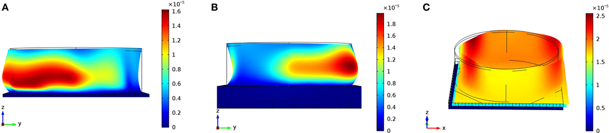
Figure 4. (A) First impulsive mode at 4.15 Hz for a broad tank on a traditional foundation; (B) first impulsive mode of a broad tank on the proposed smart foundation at 3.95 Hz; and (C) first impulsive mode at 2.4 Hz for a broad tank on the optimized foundation.
The impulsive frequency of the structure increases as the fluid level decreases. For this reason, the tank with a liquid level of 12 m was also studied. Relevant outcomes of the modal analysis for the two tank configurations are reported in Table 2. On the basis of these results, a frequency region that covers both frequencies for each tank would be desirable. Due to the fact that the fluid level can drop below 12 m, band gaps that stretch even beyond the increased impulsive frequency of the 12 m fluid level constellation were chosen for all the designs. For the standard tank this resulted in an aspired frequency region between 3.5 and 6 Hz, while the optimized design was aimed at a frequency range between 2.40 and 4.5 Hz.
Unit Cell Design of the Original Smart Foundation
The unit cell was studied as a 2D problem in Comsol Multiphysics. When applying the Floquet–Bloch boundary conditions introduced in Section “Floquet–Bloch Theorem and Brillouin Zone,” the dispersion relation can be obtained by calculating the eigenfrequencies of the system for different values of the wave vector q. Therefore, it is sufficient to calculate the eigenfrequencies along the boundaries of the Brillouin zone, depicted for clarity, in the bottom left of Figure 5A. Here, T, X, M mark the corners of the Brillouin zone, while bz denotes the edge length, which amounts to π/a = 0.7854 1/m, where a defines the size of the unit cell.
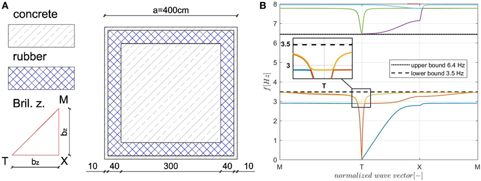
Figure 5. (A) The unit cell and its Brillouin zone (dimensions in cm); (B) dispersion analysis of the unit cell.
Our parametric study shows that a unit cell with side length, outer wall thickness, rubber coating and inner concrete cube size equal to 4, 0.1, 0.4, and 3 m, respectively, see Figure 5A, creates a band gap with a lower bound of 3.5 Hz and an upper bound of 6.4 Hz as highlighted in Figure 5B. By looking at the results in Table 2, this configuration represents the optimal design to reduce tank vibrations in the frequency range where waves can cause the greatest damage.
Note that the shear wave velocity is very close to the pressure wave velocity for the diagonal path M to T of the Brillouin zone. Therefore, the shear wave branch is almost coincident with the pressure wave branch in both Figures 5B and 12B.
The effectiveness of the proposed solution in the low frequency range is in line with the results presented by Achaoui et al. (2016), who proposed iron spherical resonators endowed with ligaments embedded in soil. However, the actual feasibility of their interesting design proposal has yet to be investigated.
Static Analysis
Three essential components have to be verified under static loads for the original design: the top slab, the walls and the intermediate slab. When the system is subjected only to static loads, the walls need to resist only compressive stresses. According to EN 1992-1-1 (2003), it is sufficient to verify that the compressive stress is lower than the design strength of concrete. As stated in Section “Materials,” a strength grade of C30/37 was assumed. Since the maximum stress of 3.6 N/mm2 shown in Figure 6A is below the design strength of 20 N/mm2, the walls are checked for gravity loads.
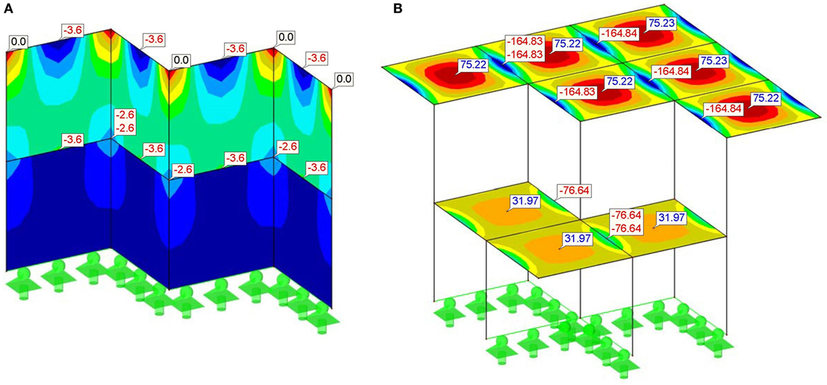
Figure 6. (A) Compressive stresses in the walls at the ultimate limit state (N/mm2) (B) line bending moments in slabs at the ultimate limit state (kNm/m).
The slabs need to sustain the flexural moments produced by static loads. This results in tension regions in the concrete matrix, see Figure 6B, which need to be reinforced in order to offer sufficient load-bearing capacity. Additionally, for corrosion protection a minimum concrete cover of the reinforcement bars is needed. Since the present work considers a general case, the concrete cover was chosen to be 5 cm, which satisfies most exposition classes mentioned in EN 1992-1-1 (2003). Given the negative line moment of −164.84 kNm/m at the ultimate limit state in the top slab above the walls, see Figure 6B, the final chosen dimensions are 35 cm for the plate thickness and 12.12 cm2/m for the reinforcements depicted in Figure 7A top left. A grid of 8 rebars with a diameter of 14 mm is sufficient for this part of design. Due to the symmetry of the system, the moments are the same in x and y direction. Therefore, the selected grid has to be set in both directions. The lower layer of reinforcements needs to cover a maximum moment of 75.22 kNm/m in the slab, which results in a minimum reinforcement area of 5.39 cm2/m indicated in Figure 7B top right. A grid of 11 reinforcement bars per meter with a diameter of 8 mm fulfills the requirement.
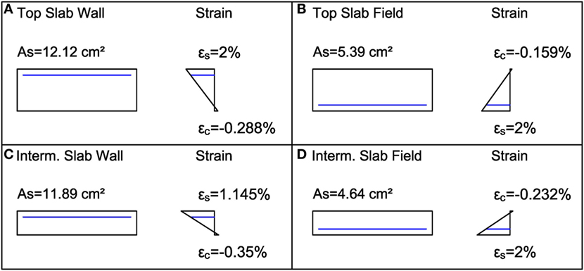
Figure 7. Summary of results for: (A) top slab above wall (top left); (B) top slab in field (top right); (C) intermediate slab above wall (bottom left); and (D) intermediate slab in field (bottom right).
The intermediate slab shows bending moments of −76.63 kNm/m above the walls and 31.97 kNm/m in the fields. When setting the slab thickness to 20 cm, the necessary reinforcement has to be 11.89 cm2/m for the top layer, see Figure 7C bottom left, and 4.64 cm2/m for the lower layer of reinforcements, look at Figure 7D bottom right. Thus, the same reinforcement grid chosen for the top slab was also sufficient for the intermediate slab.
The preliminary static evaluation of the optimized cell has been carried out as before. For the sake of brevity, only the design of columns is presented, while the remaining checks have been omitted. More precisely, the compressive concrete stresses in the columns of dimension 0.3 × 0.3 m2 amount to 18 N/mm2. This figure must be compared with a design strength of 20 N/mm2 and, therefore, the optimized design is statically valid.
Functionality Evaluation
The frequency response function at the top of the foundation for a sinusoidal excitation of amplitude 1 m/s2, plotted in Figure 8, shows a clear attenuation zone in the frequency region from 3.5 to 6.4 Hz. In this frequency region, a reader can observe that the acceleration output at the top of the foundation is smaller than the input at its bottom. An amplification area appears in the frequency region below 3.5 Hz, which is not relevant for the seismic protection of the tank. Furthermore, the influence of the number of unit cell layers has been studied. The diagrams of Figure 8 show that the number of layers is clearly connected to the attenuation effectiveness. Moreover, the effectiveness of another model with a decreased concrete wall thickness from 20 to 10 cm has been evaluated. The comparison of Figure 8A with Figure 8B highlights that a smaller wall thickness enhances the attenuation behavior and increases the intensity of the amplification area.
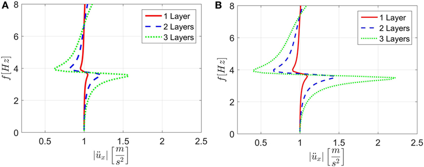
Figure 8. (A) acceleration response at the top of the foundation with a wall thickness of 20 cm and (B) acceleration response with a wall thickness of 10 cm.
In order to compare foundation typologies, the response of the complete coupled (foundation + tank) system has been studied. The model is depicted in Figure 1B and was analyzed with a concrete wall thickness both of 20 and 10 cm. For the sake of brevity, only the results corresponding to the wall thickness of 10 cm are reported herein, due to its increased effectiveness. Since the maximum acceleration does not appear at the top of the tank, the maximum acceleration along the full height of the tank wall was plotted. The comparison in terms of maximum acceleration in the frequency domain between the smart and a traditional foundation is shown in Figure 9A; the attenuation and advantages of using the smart foundation become clearly visible. Finally, the analysis of the tank with a fluid level of 12 m has been performed. Relevant outcomes in terms of accelerations are reported in Figure 9B. A careful reader can note that the attenuation due to the smart foundation is still clear but less pronounced than in the case of a fully filled tank.
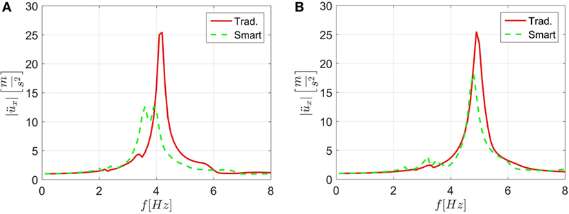
Figure 9. (A) Maximum acceleration response function of the tank wall for traditional and smart foundation and (B) acceleration responses for a tank with a reduced liquid height of 12 m.
Results for the Optimized Unit Cell
Numerical Analysis of the Optimized Cell
Based on the results obtained for the original foundation design and in order to further reduce the horizontal stiffness, we investigated an optimized design that employs columns instead of shear walls. When observing Figure 10A in contrast to both Figures 8A,B, it becomes evident that the performance of the foundation improves significantly due to the column design. The results shown in Figure 10A can also be compared to the analytical solution of Section “Analytical Model of the Optimized Cell” and the same conclusion holds. As done in Section “Functionality Evaluation,” we also analyzed the coupled system in terms of frequency response function for a base-excitation of 1 m/s2. Figure 10B shows the results of the analysis of a full tank and Figure 10C depicts the results for a tank with a liquid level of 12 m. It is apparent that in both cases the proposed isolation system can reduce vibrations in the tank significantly, in particular when the tank is totally filled with fluid and, hence, when seismic loads can produce the most severe damage.
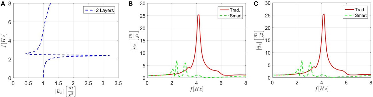
Figure 10. (A) Frequency response function of the optimized foundation alone subjected to a base acceleration of 1 m/s2; (B) tank response for a fully filled tank, on the optimized foundation, for a base acceleration of 1 m/s2 (m/s2); and (C) tank response with a liquid level of 12 m, on the optimized foundation, for a base acceleration of 1 m/s2 (m/s2).
Analytical Model of the Optimized Cell
In order to ascertain the results of our numerical study, we carried out various calculations on the analytical model introduced in Section “Analytical Model of the Optimized Design.” First, we performed a frequency response analysis on the model with 1, 5, and 25 layers. Also in this case, a base excitation of amplitude 1 m/s2 was selected and compared to the output at the top of the foundation. As shown in Figure 11A, the foundation exhibits a distinctive attenuation zone that increases with the amount of layers. This calculation was carried out without damping and is depicted in decibel [20 × log()]. Furthermore, we were interested whether a dispersion analysis of the system would yield a band gap in the predicted attenuation zone. Figure 11B shows the dispersion relation and the corresponding band gap of an infinite stack of unit cells, calculated with Eq. 10. In order to check how well the analytical model represents the numerical one and whether the analytical model can be used for further optimization investigations, we also conducted calculations on a damped system. Relevant results are shown in Figures 11C,D for Rayleigh damping of 1, 3, and 5% imposed to both 3 and 5 Hz. Moreover, an analytical study on the damped system (5% of Rayleigh damping for both 3 and 5 Hz) with a variation of the layers is reported in Figure 11D. Relevant results are discussed in Section “Discussion.”
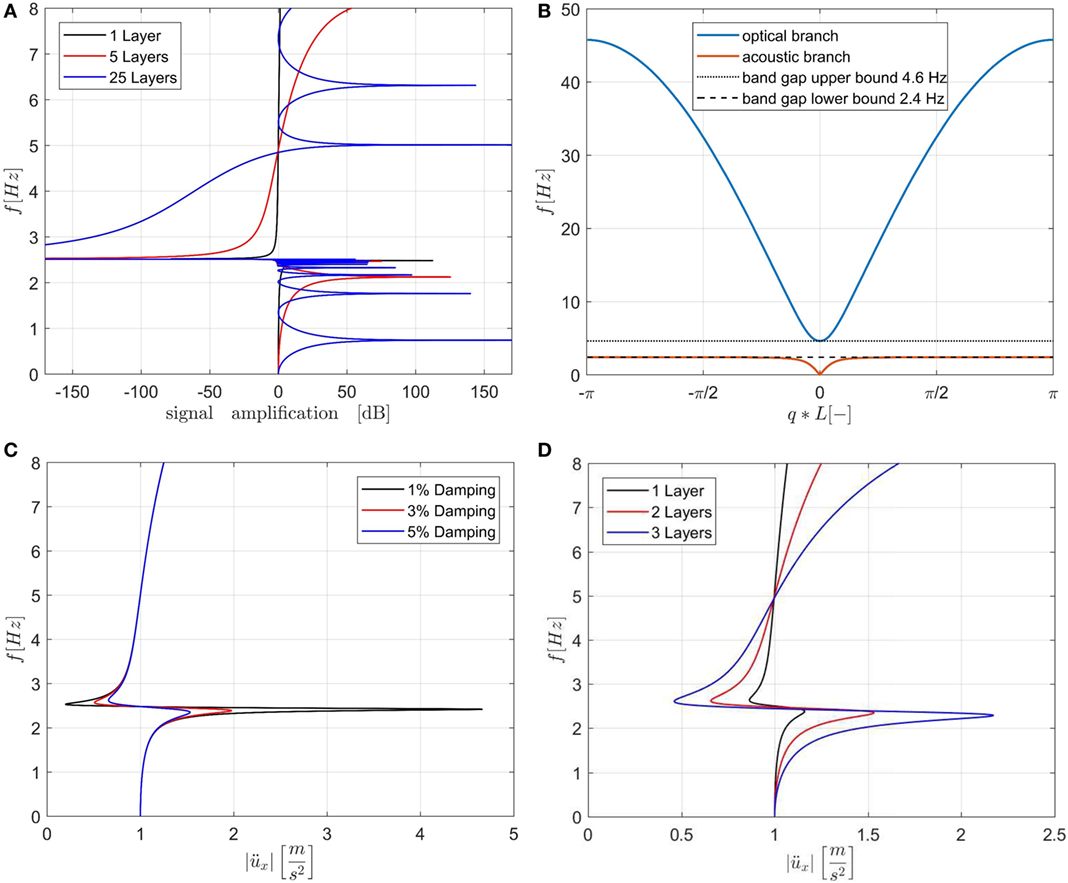
Figure 11. (A) Undamped frequency response function for 1, 5, and 25 layers of foundation for a base excitation of 1 m/s2; (B) dispersion relations for the optimized unit cell; (C) frequency response function of the analytical model for two layers and Rayleigh damping of 1, 3, and 5%; and (D) frequency response function of the analytical model with 5% Rayleigh damping and 1, 2, and 3 layers.
Influence of Small Cracks
In order to assess the influence of small cracks on elastic wave propagation, a cracked cell of the smart foundation was investigated. In fact, as shown in Figure 6B of Subsection Static Analysis of the Results section, the maximum bending moment is located where the slabs join the walls. Due to the resulting tension in concrete, small cracks appear in the area close to the internal boundaries of the walls. Therefore, the cracks were modeled as 5 cm-deep and 1 cm-wide physical gaps with no stiffness as indicated in Figures 12A,B. This was considered a conservative approach, since the presence of reinforcement bars was neglected in the cracks. In particular, two adjacent cubes along the vertical direction were endowed with small cracks and modeled in Comsol imposing Floquet–Bloch conditions.
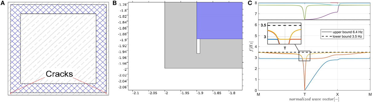
Figure 12. (A) Position of cracks in the unit cell; (B) crack modeled as a physical gap in the slabs due to static loads (dimensions in m); and (C) dispersion analysis of the cracked foundation sector.
The relevant dispersion analysis, shown in Figure 12C, must be compared to the results depicted in Figure 5B that corresponds to the uncracked unit cell. The comparison shows that the presence of small cracks slightly modifies the group velocity of propagating elastic waves.
Discussion
In Section “Unit Cell Design of the Original Smart Foundation,” we showed the dispersion relation of a unit cell that suits the needs for the isolation of a broad tank introduced in Section “Modal Analysis of a Coupled Broad-Tank-Foundation System,” with the first foundation design. Based on this unit cell, we designed a foundation and checked its static and dynamic properties in Sections “Static Analysis” and “Functionality Evaluation,” respectively. The static analysis proved that the design is feasible, while the functionality evaluation showed that the metamaterial concept is applicable even for a finite foundation. The construction practice is assumed to be in situ for the present study. Furthermore, the first design of the foundation was rather excessive in size and needed to be reduced. Based on the functionality evaluation, where in Section “Functionality Evaluation” we found a correlation between the shear stiffness of foundation walls and the attenuation effectiveness, we introduced a new design that improves the isolation performance of the foundation and reduces its size. The optimized design includes columns instead of walls, in order to reduce its shear stiffness, and replaces the rubber with uniaxial steel springs, which make the structure more versatile. The new design discussed in Section “Results for the Optimized Unit Cell” showed promising results by steady state analyses with a reduction of the foundation from 8 to 3 m in height, while improving its performance. Besides this, we verified the results with an analytical model that returned very similar outcomes compared to numerical calculations and showed that the new design still exhibits band gaps. The small discrepancy between the results with the damped analytical model shown in Figures 11C,D and those of the numerical model presented in Figure 10A are mainly due to the difference between the two models, continuous and discrete, as well as the consequences of the imposed Rayleigh damping.
Conclusion and Future Developments
In order to check the feasibility of a metamaterial-based foundation for seismic application we conceived a smart foundation that was also designed and checked for gravity loads. As a result, we found that such a structure can be realized in accordance with the Eurocode standards while maintaining favorable band-gap like properties against seismic waves. In particular, we designed two versions of the smart foundation bearing a fuel storage tank with a varying fluid level and we showed that the proposed designs can attenuate the resulting frequency range. In addition, we found that the shear stiffness of the foundation due to lateral concrete walls has a significant impact on the attenuation efficiency, and, subsequently, we proposed an optimized design where the walls were replaced with less stiff concrete columns. Though the proposed smart foundation was able to attenuate the impulsive frequencies of the fuel storage tank under different liquid levels, it cannot yet be considered as a fully optimized solution. In particular, the dynamic behavior of the system with other liquid levels needs to be investigated, as well as the performance of the coupled system under several seismic waves. Moreover, soil–structure interaction will be taken into account; especially for the benefit that soil flexibility can entail for vertical seismic excitations or vertical motions of the coupled (foundation + tank) system. Finally, given the main drawback of standard isolators, i.e., the inherent high vertical stiffness, we expect that the use of the investigated foundation for large structures characterized by rocking motion can reveal great innovative potential and undiscovered advantages.
Author Contributions
VS mainly contributed to the calculation and design of the phononic crystal lattice, as well as to the evaluation of the wave attenuation effectiveness of the finite structure. MW mainly contributed to the static evaluation, the design of the finite foundation, the crack analysis, and the analytical model of the optimized design. OB supervised VS and MW and therefore had a major influence on the broad-tank-foundation design process. GC was involved in the dispersion analysis and the design review. AM contributed to the dispersion analysis and the crack analysis, while also supporting to the design process. All designs were a result of the collaboration of all authors.
Conflict of Interest Statement
The authors declare that the research was conducted in the absence of any commercial or financial relationships that could be construed as a potential conflict of interest.
Acknowledgments
This project has received funding from the European Union’s Horizon 2020 research and innovation program under the Marie Skłodowska-Curie grant agreement no. 721816. Significant research interaction took place while ABM was visiting the University of Trento in 2016; the support from the ERC Advanced Grant “Instabilities and nonlocal multiscale modeling of materials” FP7-PEOPLE-IDEAS-ERC-2013-AdG is gratefully acknowledged.
References
Achaoui, Y., Ungureanu, B., Enoch, S., Brûlé, S., and Guenneau, S. (2016). Seismic waves damping with arrays of inertial resonators. Extreme Mech. Lett. 8, 30–37. doi: 10.1016/j.eml.2016.02.004
Barka, A. (1999). The 17 August 1999 Izmit Earthquake. Science 285, 1858–1859. doi:10.1126/science.285.5435.1858
Belakroum, R., Kadja, M., Mai, T., and Maalouf, C. (2010). An efficient passive technique for reducing sloshing in rectangular tanks partially filled with liquid. Mech. Res. Commun. 37, 341–349. doi:10.1016/j.mechrescom.2010.02.003
Carta, G., Brun, M., and Movchan, A. B. (2014). Dynamic response and localization in strongly damaged waveguides. Proc. R. Soc. A 470, 2167. doi:10.1098/rspa.2014.0136
Carta, G., Movchan, A. B., Argani, L. P., and Bursi, O. S. (2016). Quasi-periodicity and multi-scale resonators for the reduction of seismic vibrations in fluid-solid systems. Int. J.Eng. Sci. 109, 216–239. doi:10.1016/ijengsci.2016.09.010
Cheng, Z., Yan, Y. Q., Menq, F.-Y., Mo, Y. L., Xiang, H. J., Shi, Z. F., et al. (2013). “3D periodic foundation-based structural vibration isolation,” in Proceedings of the World Congress on Engineering, London, UK.
Cheng, Z., and Zhifei, S. (2013). Novel composite periodic structures with attenuation zones. Eng. Struct. 56, 1271–1282. doi:10.1016/j.engstruct.2013.07.003
Ding, W. P., and Chen, H. L. (2001). A symmetrical finite element model for structure-acoustic coupling analysis of an elastic, thin-walled cavity. J. Sound Vibr. 243, 547–559. doi:10.1006/jsvi.2000.3478
EN 1992-1-1. (2003). Eurocode 2: Design of Concrete Structures – Part 1-1: General Rules and Rules for Buildings. CEN: Bruxelles.
Fabbrocino, G., Irevolino, I., Orlando, F., and Salzano, E. (2005). Quantitative risk analysis of oil storage facilities in seismic areas. J. Hazard. Mater. 123, 61–69. doi:10.1016/j.jhazmat.2005.04.015
Gaofeng, J., and Zhifei, S. (2010). A new seismic isolation system and its feasibility study. Earthq. Eng. Eng. Vibr. 9, 75–82. doi:10.1007/s11803-010-8159-8
Ha, Y.-K., Kim, J.-E., Park, I.-W., and Lee, H. Y. (2002). Propagation of water waves through finite periodic arrays of vertical cylinders. Appl. Phys. Lett. 81, 7. doi:10.1063/1.1499520
Huang, H. H., Sun, C. T., and Huang, G. L. (2009). On the negative effective mass density in acoustic metamaterials. Int. J. Eng. Sci. 47, 610–617. doi:10.1016/j.ijengsci.2008.12.007
Liu, M., and Gorman, D. G. (1995). Formulation of Rayleigh damping and its extensions. Comput. Struct. 57, 277–285. doi:10.1016/0045-7949(94)00611-6
Liu, Z., Zhang, X., Mao, Y., Zhu, Y. Y., Yang, Z., Chan, C. T., et al. (2000). Locally resonant sonic materials. Science 289, 1734–1736. doi:10.1126/science.289.5485.1734
Malhotra, K. P., Wenk, T., and Wieland, M. (2000). Simple procedure for seismic analysis of liquid-storage tanks. Struct. Eng. Int. 10, 197–201. doi:10.2749/101686600780481509
Phani, A. S., Woodhouse, J., and Fleck, N. A. (2006). Wave propagation in two-dimensional periodic lattices. J. Acoust. Soc. Am. 119, 1995–2005. doi:10.1121/1.2179748
Shi, Z., and Huang, J. (2013). Feasibility of reducing three-dimensional wave energy by introducing periodic foundations. Soil Dyn. Earthq. Eng. 50, 204–212. doi:10.1016/j.soildyn.2013.03.009
Sigalas, M., Kushwaha, M. S., Economou, E. N., Kafesaki, M., Psarobas, I. E., and Steurer, W. (2005). Classical vibration modes in phononic lattices: theory and experiment. Zeitschrift für Kristallographie Cryst. Mater. 220, 9–10. doi:10.1524/zkri.2005.220.9-10.765
Keywords: seismic isolation, multiscale resonators, metamaterials, smart foundations, fuel storage tanks, earthquake engineering
Citation: La Salandra V, Wenzel M, Bursi OS, Carta G and Movchan AB (2017) Conception of a 3D Metamaterial-Based Foundation for Static and Seismic Protection of Fuel Storage Tanks. Front. Mater. 4:30. doi: 10.3389/fmats.2017.00030
Received: 06 April 2017; Accepted: 27 September 2017;
Published: 17 October 2017
Edited by:
Federico Bosia, Università degli Studi di Torino, ItalyReviewed by:
Anna Marina Pandolfi, Politecnico di Milano, ItalyGennady Mishuris, Aberystwyth University, United Kingdom
Copyright: © 2017 La Salandra, Wenzel, Bursi, Carta and Movchan. This is an open-access article distributed under the terms of the Creative Commons Attribution License (CC BY). The use, distribution or reproduction in other forums is permitted, provided the original author(s) or licensor are credited and that the original publication in this journal is cited, in accordance with accepted academic practice. No use, distribution or reproduction is permitted which does not comply with these terms.
*Correspondence: Vincenzo La Salandra, dmluY2Vuem8ubGFzYWxhbmRyYUB1bml0bi5pdA==;
Moritz Wenzel, bW9yaXR6LndlbnplbEB1bml0bi5pdA==