 Nicholas Maus
 Faramarz Gordaninejad
- Composite and Intelligent Materials Laboratory, Department of Mechanical Engineering, University of Nevada, Reno, NV, United States
The goal of this study was to demonstrate the feasibility of a novel fail-safe, bi-directional liquid spring, controllable magnetorheological fluid damper (BDLS-CMRD). This research introduces a device with independently pre-set spring forces in compression and rebound combined with controllable MR fluid damping. The BDLS-CMRD can potentially replace traditional metal spring-damper suspension systems. Bulky and heavy metal spring-damper suspension systems can be upgraded to the smaller and lighter BDLS-CMRD, reducing the mass of vehicle suspensions. In this work, a BDLS-CMRD was designed, fabricated, tested, and evaluated in three phases. The first design phase demonstrates the concept of a liquid spring with different spring forces in compression and rebound. The second phase incorporates viscous fluid damping of pure silicone fluid with the first phase BDLS. The final design phase combines a controllable magnetorheological fluid (MRF) damper with the first phase BDLS. This study presents the response of the BDLS-CMRD in a wide range of preloaded conditions and frequencies. Experiments were performed for sinusoidal displacements in the quasistatic and dynamic ranges to evaluate the performance of the BDLS-CMRD under different magnetic fields. The experimental results demonstrate that the device operates with significantly different spring forces from the compression to rebound regions, while providing passive viscous fluid damping or controllable MR fluid damping. This system has successfully demonstrated that the utility of a bi-directional liquid spring can be combined with the reliability of passive viscous fluid damping and the capabilities of controllable MR fluid damping into one compact and versatile device.
Introduction
The role of vibration and shock isolation has been filled traditionally by heavy metal springs and passive dampers. These traditional suspension systems are heavy and bulky. To make vehicles lighter and more adaptable, buildings and structures more resilient, and sensitive instruments more durable, a complete suspension system upgrade and replacement is necessary. This proposed system presents such a system.
The “Double-acting liquid spring” was first introduced in 1959 (Zumwalt, 1959). Double acting or bi-directional liquid springs are devices capable of reaction forces in both compression and rebound. Similar to traditional metal springs, the reaction forces of a bi-directional liquid spring seek to return the spring to its initial position or equilibrium. However, unlike traditional metal springs, bi-directional liquid springs can have different reaction forces in compression and rebound.
This device demonstrates a force in compression that is three times that of its force in rebound. This force can be “tuned” by setting the available volume in either chamber, making this device's performance more adaptable in a similar size system when compared to traditional suspension systems. This unique dual chamber device utilizes compressible fluid springe rates in both compression and rebound by displacing a small piston from a neutral position between the chambers. The displacement compresses the MRF and results in a spring force counter to the force causing the displacement. An MR valve is incorporated in a manner that also functions as a passive annular damping valve to result in damping in the “off” or unpowered state.
Other studies have theorized the possibility of such a bi-directional liquid spring combined with passive viscous fluid damping (Samantaray, 2009). That work seeks to theoretically analyze a liquid spring damper that works in both compression and rebound and even suggests a possible design for a test apparatus, though no prototype is developed and/or tested in that study.
Magnetorheological fluid devices use magnets to control the properties of the MRF. In most devices electromagnets are used to control the viscosity and yield stress as a function of input electric current. These devices typically incorporate the electromagnet into the valves or narrow passages of the device. Potnuru et al. (2013) modeled, developed, and tested a double-ended, but not bi-directional, controllable MRF liquid spring damper. Raja et al. (2013) presented the design and development of a compressible magnetorheological damper where a theoretical model that considers the compressibilty of a magnetorheological fluid damper is developed and verified by the testing and evaluation of a prototype device. McKee et al. (2018) explored the temperature dependency of MR fluid and includes a comprehensive study of reciprocating seals. Hong et al. (2006) investigated a double-ended automotive strut that is filled with a compressible MR fluid. Hong experimentally verified a model that considers the compressibility for both the liquid spring and the compressible flow through the MR valve. Wang and Gordaninejad (2008) compiles and reviews the current state of compressible MR technology.
In this work, a novel fail-safe, bi-directional liquid spring, controllable magnetorheological fluid damper system (BDLS-CMRD) is designed, fabricated, tested, and evaluated. This proposed system is the first to combine a bi-directional liquid spring with fail-safe passive viscous fluid damping and controllable magnetorheological fluid damping in one compact device.
Design
Design Requirements
The requirements for this liquid spring device include bi-directionality, a maximum internal pressure of 41.37 MPa (6,000 psi) in order to operate the linear compressibility region (Lichtenthaler et al., 1978; Sandberg and Sundqvist, 1982), and an experimental range of 2.54 cm in each direction. As a result of this pressure range, the device is capable of a spring force of up to 437.8 N/mm (2,500 lb/in). The experimental device is ~30 cm tall and 15 cm in outside diameter. The chambers are ~10 cm inside diameter and 8 cm in depth.
This unique two-chamber design allows for the device to have equal or dissimilar spring rates in compression and rebound. The device can be “pre-set” with regard to spring rate and damping. The spring rate in both compression and rebound can be pre-set independently. By initially assembling the device with different solid masses in either chamber, the initial volume of the chamber was altered. By precisely designing these masses, the volume of the fluid was controlled, and the spring rate was determined. A mass that displaces ~50% of the original initial volume was tested. This mass allows for the maximum force of 11.1 kN (2,500 lb) in order to stay within the linear compression region. Figure 1 displays the cross-sectional view of the BDLS–CMRD tested in this study.
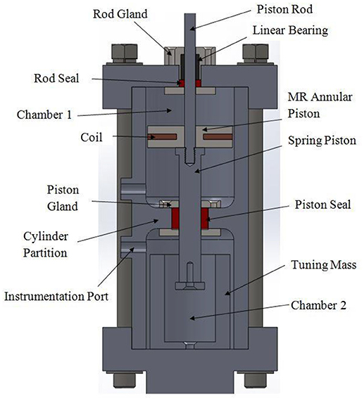
Figure 1. A cross-sectional view of the BDLS-CMRD shows the general arrangement including: seals, pistons, glands, and tuning mass. Reproduced with permission from Maus and Gordaninejad (2014).
Figure 1 illustrates how the rod gland is held together by the bearing retainer and the internal retainer. Also, Figure 1 shows how the spring piston is held by the piston gland which is contained within the cylinder partition. The MR piston is attached to the piston rod directly on top of the spring piston in chamber 1. To increase the spring constant in compression, the tuning mass is installed to lower the initial volume in chamber 2.
Seal Gland Design
Due to the unique design of BDLS-CMRDs, internal forces on the spring piston seek equilibrium at the displacement that was set when the device was assembled and filled with the working fluid. Also, the device allowed for different spring rates in compression and rebound by changing the initial volume of the chambers. The model was constructed by first finding the pressures individually for each chamber, which can be expressed by:
where Pn is the pressure corresponding to a specific chamber, Ap is the area of the spring piston, and Pi is the initial pressure. Since the chambers are filled with a fluid, the pressures cannot be negative. For values ≤0, the pressure values are zero. An expression for the spring force of a liquid spring is (McKee et al., 2018):
where x is the displacement, Vn is the volume of the same specific chamber, and β is the bulk modulus. Combining Equations (1–3), the spring force for a single chamber is:
Since the pressure in the opposing chambers results in opposite forces, these forces can be added to achieve a force balance. The force in chamber 1 is added to the force in chamber 2, resulting in a total spring force of Fspring. Internal friction is a key consideration in the modeling of a BDLS-CMRD. Due to the design requirements of the seals, friction can be a significant contribution to the total force of the device. Friction, in this model, is characterized as a constant friction and a dynamic friction. Constant friction consists of two forces and is considered to be the normal friction force of the seal against the surfaces of the rod and piston. Constant friction, Ff, is found experimentally to be 178 N (40 lb); the experimental procedure will be discussed later. The dynamic seal friction, Ffd, is:
where As is the area of the seals in contact with the piston and rod, and P1 and P2 are the pressures in the bottom and top chambers, respectively (Dixon, 2007). Since there are two seals working simultaneously in opposition, the dynamic seal friction from Equation (5) becomes:
then:
where Pa is the ambient pressure outside the device.
Thus, the total seal friction is:
where dynamic seal friction is subtracted from the constant friction term when velocity is positive and added when velocity is negative. The model predictions for the bi-directional liquid spring and seal friction characteristics are shown in Figure 2.
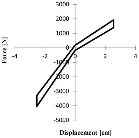
Figure 2. Force displacement plot for the bi-linear liquid spring seal friction is illustrated with experimental data.
Buckling of the piston rod is of primary concern. Finite element analysis (FEA) is performed to ensure a gland design that limits rod buckling. In the FEA, a linear bearing, or “bushing bearing,” is modeled in frictional contact with the rod. Using a single mode Euler buckling model, the reaction force between the rod and bearing is found when the rod is subjected to a compressive load. The displacement of the contact point between the rod and the bearing is found to determine the radial loading on the bearing surface. This information is crucial in bearing selection since bearings are rated by radial load. It is found that at a compressive axial load on the rod of 11.1 kN (2,500 lb), a bearing rated for 0.27 kN (60 lb) is adequate to support the radial load, restricting the buckling of the rod. Figure 3 shows the results of the linear buckling FEA model, a solid model of the gland assembly, and the profile of the R54 seal gland assembly.
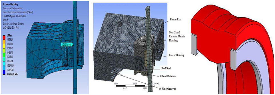
Figure 3. (Left) A one quarter, three-dimensional finite element linear buckling model is used to determine radial displacement and force, (Middle) One quarter, three-dimensional gland assembly model showing the upper gland design. (Right) Custom R54 seal design.
A bearing takes the shear load off of the seal while allowing the rod to travel in the axial direction. Bearings are commercially available in sizes up to 5 cm in diameter and can be custom fabricated to almost any size. These bearings are made in many different configurations and from a variety of materials. Larger bearings for higher loads are commonly made of bronze and incorporate grooves and channels for additional lubrication. Smaller linear bearings are typically made of aluminum and lined with Teflon to minimize friction on the piston rod.
Figure 3 shows how the piston rod is retained by the gland assembly. The gland assembly consists of a linear bearing and a rod seal. The linear bearing is pressed into the top gland retainer, and the entire assembly is held internally by the lower gland retainer. The seal between the cylinder heads and the outer cylinder wall is accomplished by compressing a pair of O-rings into the O-ring grooves.
Selection of seals for this device can be a challenge due to the pressure requirements. Other considerations are rod speed, temperature, chemical resistance, and size restrictions. Pressure is of primary concern because the seal must hold uneven pressures from either side of the gland. Conventional V-packing is one directional and leaks slowly from one chamber to the other, resulting in a change of equilibrium for the device. Standard PTFE U-seals are not well suited for low viscosity/high pressure service. These seals tend to be designed for either low viscosity or high pressure, not both. A high-performance seal is needed to meet all the requirements. High-performance seals that will not leak low viscosity fluid under high pressure are custom-made for this system. These retain uneven pressure from both sides of the gland and are capable of withstanding moderately high rod velocities and temperatures. The seals incorporate an 8% diametric compression. The seal material is Duralast 4203, and the incorporated back-up rings are Permachem 66431. These materials are ideal for low and high viscosity silicone oil under high pressure. Figure 3 shows the profile of the seal.
Shear force is a force acting perpendicular to the normal axial forces experienced by liquid springs and dampers. The foremost effect of shear loading is uneven force on the seal and gland. In standard operation the seal exerts even force all around the rod due to the seal having a smaller internal diameter than the rod's outer diameter. This interference fit compresses the seal (that is made of considerably softer material than the rod) and creates an interface to retain pressure. When the seal is loaded in shear, the force of compression is not uniform. If the non-uniformity is sufficiently large, the interface between the seal and rod may not be sufficient to retain the pressure. In extreme cases, the compression of the seal may be so high that an actual gap occurs between seal and rod. Higher shear forces can bend the rod, resulting in damage to either the gland or the rod or both. Any damage to the rod would prematurely wear the seal or possibly cause immediate failure. The most common solution to shear loading of these devices is to incorporate a linear bearing.
MR Valve Design
Damping force at given velocities and amperages can be tuned by changing the gap between the annular piston and the chamber wall. The gap for the frequency and force range selected was determined to be 1 mm. Each data point in Figure 4 shows the maximum magnetic field at 5 Amps through the MRF at each gap width modeled and the orientation of the magnetic coil within the damping piston. The magnetic field in the MRF decreases as the annular piston gap is increased.
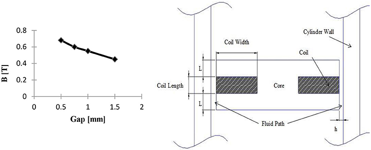
Figure 4. (Left) The magnetic field density at 5 Amps decreases as the gap width increases from 0.5 to 1.5 mm. In order not to exceed the load limit of 11.1 kN (2,500 lb) at 4 Hz and 5 Amps, it is necessary to incorporate a 1mm gap. (Right) The diagram of electromagnetic piston and annular valve. Reproduced with permission from Maus and Gordaninejad (2014).
An electromagnet was incorporated into the damping piston. A magnetic path was developed from one end of the piston to the other when an electric current was applied. This magnetic path travels through the cylinder wall and the MR fluid because both are magnetically permeable.
The annular MR piston incorporated 22-gauge enameled copper wire. Using a staggered packing order it was determined that a 4.8 mm by 25.4 mm area can be filled with 225 windings of 22 gauge wire. These dimensions allowed for the optimal ratio of amp turns to valve length for the geometric restrictions of the device. The 22-gauge wire was optimal for this application because it produced the highest number of amp turns while operating at 5 Amps continuous current. Table 1 shows the magnetic field as a function of amperage for the optimized geometry and wire gauge. The values for the magnetic field, B in Tesla, were determined by FEA and added to the table. Figure 5 illustrates the magnetic field in the MR valve predicted by FEA and presented the data in Table 1.
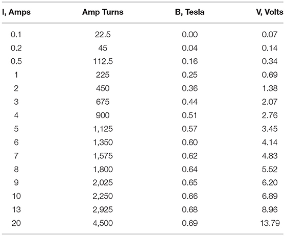
Table 1. The magnetic field through the annular MR valve reaches saturation above 5 amps and exceeds geometric constraints near 1,100 amp turns.
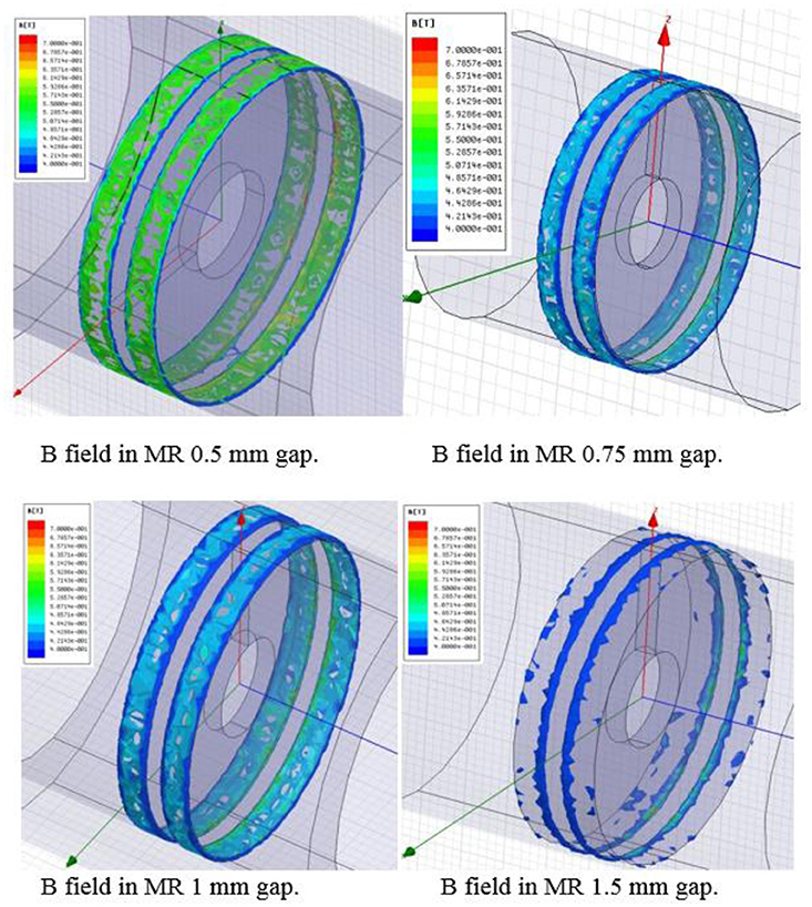
Figure 5. The magnetic field in the MRF is shown to decrease as the gap is increased.
Electromagnetic Finite Element Analysis
Finite element analysis was performed using Ansoft software to solve for the magnetic field through the MR valve. This model assumes uniform temperature and fluid properties. Figure 5 shows how the magnetic field through the MR valve decreases due to the lower permeability of the MR fluid compared to the high iron alloys of the piston and cylinder wall. As the gap is increased, more of the less permeable fluid separated the more permeable materials. The maximum magnetic fields of 0.57 Tesla is achieved by the 0.5 mm valve gap at 5 amps. The yellow to red regions in the figure along the edges of the coil and the perimeter of the damping piston indicate the location of the highest field strength.
Experimental Setup
Rheology
A Physica MCR 300 shear rheometer with data acquisition capable of testing MRF at various temperatures and magnetic fields was used to obtain the fluid properties of yield stress and viscosity.
The carrier fluid for these tests was 5 centistokes (cSt) pure silicone fluid. For the final BDLS–CMRD test, an MR fluid was prepared in-house. The MR fluid consisted of Grade–R−2410 Micropowder Iron (Carbonyl Iron) and the 5 cSt pure silicone fluid. The MR fluid was mixed at a ratio of 80% by weight iron particles to 20% by weight silicone oil. The fluid was mixed using a variable speed mixer for 20 min at 900 rpm to ensure the particles are uniformly dispersed within the carrier fluid.
The rheometer performs tests of shear rates from 0 to 400 s−1 while recording values for shear stress, viscosity, and shear rate. All tests were performed with a 28 mm measuring plate set to a gap of 1 mm. A 0.3 mL test sample was used in all tests. Each test was conducted three times to ensure accuracy. A magnetic field can be induced to find these properties for various current levels used to control an MR device. Current levels were correlated to their respective magnetic field values using the Ansoft model described in the previous section. For the MR fluid tests, the magnetic field for 0, 1, and 2 Amps through the internal electromagnet correlated to 0, 0.29, and 0.56 Tesla, and values of τ(I) in Pa were 94.4, 17,247.7, and 22,555.7, respectively.
Quasistatic Test
Quasistatic tests for the bulk modulus, pressures in chambers 1 and 2, and the spring force profiles were performed on an Instron 4210 screw-drive machine. All quasistatic tests were performed at 25.4 cm/min corresponding to 0.016 Hz and were repeated three times. A LabVIEW program was written to record the data from the load cell, linear velocity and displacement transducer (LVDT), and pressure transducers, then to transcribe that data to a spreadsheet. Figure 6 illustrates the test setup. Also shown, attached to the device, are the valves and hydraulic lines used to fill and pressurize the device.
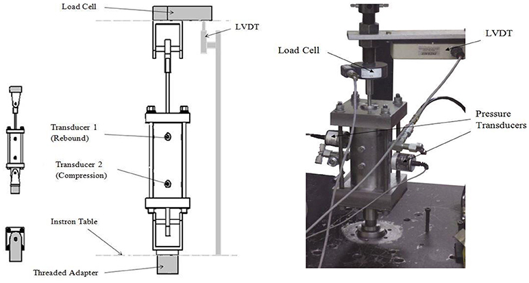
Figure 6. Schematic and photograph of quasistatic test setup showing the placement of the transducers, LVDT, load cell, and attachment to the screw-drive machine.
Dynamic Test Setup
Dynamic tests were accomplished using an MTS damper testing system. The setup for dynamic testing was nearly identical to the quasistatic case, the difference being that the MTS has an internal LVDT. Tests were conducted first on the liquid spring damper configuration. Test frequencies range from 0.01 to 12 Hz. All tests utilize a 2.54 cm displacement in both compression and rebound and are conducted three times. Next, BDLS–CMRD tests were accomplished on the same equipment. These tests also cover the full displacement of the device, although the frequency range was decreased to 0.01 to 4 Hz.
Experimental Study
A series of tests were conducted to characterize the BDLS–CMRD configuration. The amperage range of 1 to 5 Amps was selected because of the continuous current capacity of the 22-gauge wire used in the electromagnetic coil. The frequency range was selected to limit the maximum compressive force to 11.1 kN as predicted by the BDLS-CMRD model. The maximum external load for buckling of the piston rod was found to correspond with 4 Hz at 5 Amps for the BDLS-CMRD configuration. Tests are conducted for frequencies of 0.1, 1, 2, 3, and 4 Hz at 0, 1, 2, 3, 4, and 5 Amps. All tests are repeated three times. Tests are accomplished using an MTS damper testing system. All tests utilize a 2.54 cm displacement in both compression and rebound and are conducted three times.
Results
Unloaded Pre-pressurizing
Pre-pressurizing this device resulted in a phenomenon of multi-linearity. “Pre-pressurizing” the device involved increasing the pressure in one or both chambers to simulate preloading without allowing the device to shift from the zero displacement or neutral position. The device was secured in the load testing machine and a hand pumped accumulator was used to increase pressure. This process was monitored with pressure transducers and verified with calibrated pressure gauges. Multi-linearity manifested in five distinct regions. Figure 7 shows from left to right that at the most extreme compression (zone 1), there is a softening followed by a higher spring rate (zone 2) followed by a constant force (zone 3) as the device reaches its displacement equilibrium. Continuing from left to right, the force then returns to a higher spring rate (zone 4) and finally softens again as the device reaches its full displacement in rebound (zone 5). The experimental results, shown as a solid line are compared to the theoretical results as modeled by solving equations one through eight at each discrete displacement in the experimental range.
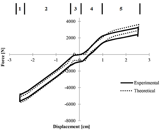
Figure 7. Force displacement curves for 6.89 MPa symmetric pressure illustrating the zones of performance.
The softening regions occurred when only one chamber of the device was under pressure and there was no opposing force, resulting in a lower net force. Figure 8 illustrates how pressure differential was affected by 6.89 MPa symmetric pressurization. Again, the multi-linear zones are shown to demonstrate how the difference in pressure relates to the total force of the device.
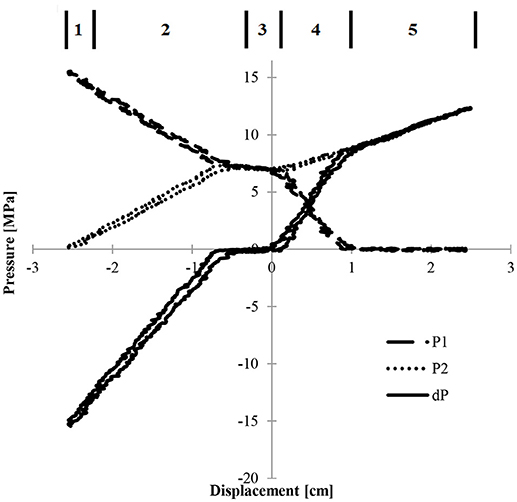
Figure 8. Pressure versus displacement curves in chambers 1 and 2 (P1 and P2, respectively) and the corresponding pressure differential, dP showing the multi-linear zones of the device.
The net force decreased when one of the pressures approaches zero. Constant force of the central region (zone 3) was due to the seal friction being the dominant force. In this region, the pressure differential, and therefore the force differential, is less than the force due to seal friction. The softening region at the right of curve P1 was due to the lower chamber having zero pressure (zone 5).
Bi-Directional Liquid Spring
Quasistatic testing is performed and compared to the liquid spring model. The model is an idealized case and does not exactly follow the curving lines of the experimental data. The discrepancy between model and experimental data is small, and maximum forces in both compression and rebound vary no more than 3% from the experimental results. Figure 9 compares the quasistatic test results and the theoretical model.
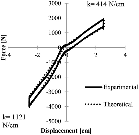
Figure 9. Force displacement results of the liquid spring theoretical model with seal friction accurately predict the quasistatic experimental data.
Seal Friction Characterization
Figure 10 shows the two most extreme cases when considering hysteresis due to seal friction.
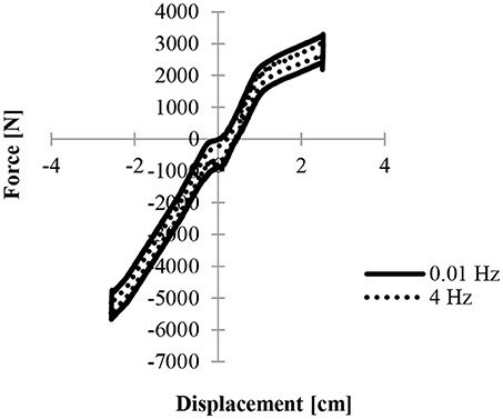
Figure 10. Force displacement curves for seal friction in the quasistatic (0.01 Hz) and dynamic (4 Hz) regions indicating that seal friction does not dramatically increase with velocity.
A difference of < 100 N can be seen when comparing quasistatic experimental results to 4 Hz dynamic data. This difference is < 2% of the maximum compressive force.
Symmetric Pressurizing
Symmetric pressurization allowed for the testing and controlling of the multi-linear regions. “Symmetric Pressurizing” was accomplished by pre-pressurizing both cylinders equally. As initial pressures were increased, the multi-linear regions become more apparent. Figure 11 displays how the symmetric pressurization results become more multi-linear as initial pressure is increased.
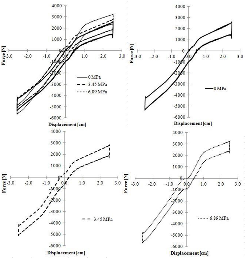
Figure 11. Comparison of quasistatic symmetric, symmetrically pressurized force displacement curves at 0, 3.45, and 6.89 MPa shows the development of the multi-linear regions.
Preloading
Figure 12 demonstrates how preloading shifts the multi-linear results. “Preloading” involved pre-pressurizing one chamber in order to reach an initial load or reaction force in compression or rebound. That force was measured using a load cell attached between the test machine and the connecting rod of the device. Preloading in compression shifts the curve down while preloading in rebound shifts the curve up. The results are shifted proportionally; that shift can be estimated by multiplying the internal pressure of either chamber by the cross-sectional area of the spring piston. The Figures compare the unloaded results with the preloaded results in order to show the increase in multi-linearity. Figure 12 (Bottom) also shows how the plots are shifted as preloading is increased in compression and rebound, respectively. Notice that the curves are shifted farther in their respective directions due to the increase in initial pressure. Also, the results are becoming more multi-inear due to the combination of forces.
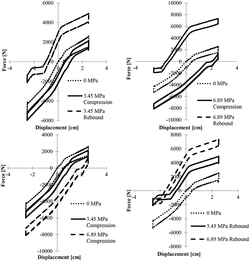
Figure 12. (Top Left) Force displacement plot for quasistatic preloading in compression and rebound at 3.5 MPa compared to 0 MPa initial pressures illustrates the developing multi-linearity. (Top Right) Force displacement plot for quasistatic preloading in compression and rebound at 6.89 MPa. (Bottom Left) Comparison of quasistatic force versus displacement over the range of 0 to 6.89 MPa preloading in compression illustrates the shift in the multi-linearity. (Bottom Right) Comparison of quasistatic force versus displacement over the range of 0 to 6.89 MPa.
Figure 12 demonstrates a comparison between the symmetric pressurization curve and preloading in both compression and rebound. The Figures show how symmetric pre-pressurizing and preloading result in similar multi-linearity. Figure 12 also shows that softening regions occur when only one chamber of the device is under pressure. Since only one chamber is under pressure, there is no opposing force, resulting in a lower net force. The regions of constant force are due to the opposing forces being smaller than the constant seal friction. Since the seal friction is constant at quasistatic speeds and that constant force is dominant, the force displacement curve shows a region of constant total force.
Viscous Damping
This device can be configured as a passive liquid spring damper. A theoretical model is developed to predict the passive viscous fluid damping combined with a bi-directional liquid spring. Figure 13 displays the model verification along with the 6 Hz experimental results.
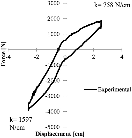
Figure 13. Force displacement plots of the viscous fluid damping bi-directional liquid spring experimental results for a sinusoidal input of 2.5 cm at 6 Hz feature the different spring rates in compression and rebound.
BDLS-CMRD Full Device Demonstration
The anomalous spikes in the test data are caused by the control system of the test apparatus as the device changes from a negative reaction force to a positive reaction force. The zero force allows inertial forces to be dominant just before being damped out by the device. Figure 14 demonstrates the bi-directional spring forces in the active MR state. The maximum spring force recorded in compression was 2,328 N/cm and the maximum in rebound was found to be 980 N/cm. Tests were conducted to show that the bi-directional liquid spring functions as a controllable liquid spring damper. In these tests it was apparent that bi-linearity is maintained even at maximum MR fluid damping. Figure 14 (Left) shows how maximum MR fluid damping force and spring force increase as amperage increases in the BDLS–CMRD. The Figure shows an increase of damping force of more than 250% and a 200% increase in maximum spring force. The increase in damping force is due to MR fluid damping, while the increase in spring force is due to a combination of the higher shear stress and lower initial volume of compressible carrier fluid. Note that the spring rates in compression and rebound are the same for every input current. This is because spring rate is a geometric property and not a function of magnetic field. Figure 14 (Right) compares the experimental results for the frequency range of 0.1 to 4 Hz at 5 Amps. Damping increases and frequency increases, but the spring rates stay constant with respect to frequency. Every plot has nearly the same spring rates for compression and rebound due to the spring rate being a function of initial volume.
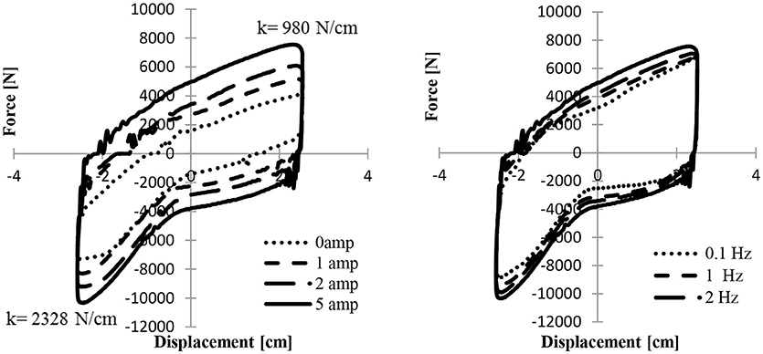
Figure 14. (Left) Force displacement plots for BDLS-CMRD with a sinusoidal input of 2.5 cm at 4 Hz and 0, 1, 2, and 5 Amps illustrating the increasing MR effect. (Right) Force displacement plots for BDLS-CMRD with a sinusoidal input of 2.5 cm at 0.1, 1, 2, and 4 Hz.
Summary and Conclusions
A system is proposed to demonstrate the feasibility of combining a bi-directional liquid spring capable of acting independently in compression and rebound with fail-safe passive viscous fluid damping and controllable MR fluid damping. A theoretical model is developed for the design and characterization of the BDLS-CMRD. The modeling of the individual aspects of the device is broken into bi-directional liquid spring, viscous fluid damping, and MR fluid damping, then the aspects combined to present the entire modeled device. The model incorporates the compressibility and bulk modulus of a fluid, the force due to seal friction, the flow through an annular valve, and the Bingham plastic model for MR fluids. Experiments are conducted to evaluate the performance of the device for its bi-directional liquid spring, viscous fluid damping, and MR fluid damping capabilities. Model verification and experimental results cover the combination of forces, spring force, and pressure. Verification of the viscous fluid damping model is presented followed by experimental results for the complete BDLS-CMRD.
A bi-directional liquid spring can be combined with both fail-safe viscous fluid damping and controllable MR fluid damping into a compact light-weight system. This system can be designed to have different spring rates in compression and rebound that are apparent through all operating frequencies and magnetic fields.
Author Contributions
All authors listed have made a substantial, direct and intellectual contribution to the work, and approved it for publication.
Conflict of Interest Statement
The authors declare that the research was conducted in the absence of any commercial or financial relationships that could be construed as a potential conflict of interest.
Acknowledgments
This research was partially supported under a US Army contract number W56HZV-07-C-0459. A preliminary version of this study was published in Maus and Gordaninejad (2014).
Footnotes
1. ^ American High Performance Seals http://www.ahpseals.com/products/rod.php#2. American High Performance Seals, Inc.
References
Hong, S. R., Wang, G., Hu, W., and Wereley, N. M. (2006). Liquid spring shock absorber with controllable magnetorheological damping. Proceedings of the Institution of Mechanical Engineers, Part D. J. Automobile Eng. 220, 1019–1029. doi: 10.1243/09544070JAUTO74
Lichtenthaler, R. N., Liu, D. D., and Prausnitz, J. M. (1978). Specific Volumes of Dimethylsiloxane Polymers to 900 Bars. Macromolecules 11, 192–195.
Maus, N., and Gordaninejad, F. (2014). “A fail-safe, Bi-linear liquid spring controllable magnetorheological fluid damper,” in Proceedings of SPIE - The International Society for Optical Engineering, Vol. 9057, Smart Materials and Structures Conference, ed Wei-Hsin Liao.
McKee, M., Wang, X., and Gordaninejad, F. (2018). Effects of temperature on performance of a compressible magnetorheological fluid damper-liquid spring suspension system. J. Intell. Mater. Syst. Struct. 29:1. doi: 10.1177/1045389X17705203
Potnuru, M. R., Wang, X., Mantripragada, S., and Gordaninejad, F. (2013). A compressible magneto-rheological fluid damper – liquid spring system. Int. J. Vehicle Design 63, 256–274. doi: 10.1504/IJVD.2013.056155
Raja, P., Wang, X., and Gordaninejad, F. (2013). A high-force controllable MR fluid damper-liquid spring suspension system. Smart Mater. Struct. 23:1015021. doi: 10.1088/0964-1726/23/1/015021
Samantaray, A. K. (2009). Modeling and analysis of preloaded liquid spring/damper shock absorbers. Simulat. Model. Pract. Theory 17, 309–325. doi: 10.1016/j.simpat.2007.07.009
Sandberg, O., and Sundqvist, B. (1982). Thermal properties of two low viscosity silicon oils as functions of temperature and pressure. J. Appl. Phys. 53, 8751–8755.
Keywords: fail-safe, bi-directional, liquid spring, controllable, magnetorheological fluid damper
Citation: Maus N and Gordaninejad F (2019) A Bi-Directional, Liquid-Spring-Magnetorheological-Fluid-Damper System. Front. Mater. 6:6. doi: 10.3389/fmats.2019.00006
Received: 06 September 2018; Accepted: 14 January 2019;
Published: 04 February 2019.
Edited by:
Weihua Li, University of Wollongong, AustraliaReviewed by:
Xufeng Dong, Dalian University of Technology (DUT), ChinaHuaxia Deng, Hefei University of Technology, China
Copyright © 2019 Maus and Gordaninejad. This is an open-access article distributed under the terms of the Creative Commons Attribution License (CC BY). The use, distribution or reproduction in other forums is permitted, provided the original author(s) and the copyright owner(s) are credited and that the original publication in this journal is cited, in accordance with accepted academic practice. No use, distribution or reproduction is permitted which does not comply with these terms.
*Correspondence: Faramarz Gordaninejad, ZmFyYW1hcnpAdW5yLmVkdQ==