 Wei-Min Zhong
 Xian-Xu Bai
- Laboratory for Adaptive Structures and Intelligent Systems (LASIS), Department of Vehicle Engineering, Hefei University of Technology, Hefei, China
Inerters are two-terminal mass elements in which the forces applied at the terminals are proportional to relative acceleration between the nodes. The volume and weight of inerters are much smaller than those of any conventional mass element for the same force, which is beneficial for engineering applications. The inerter in mechanical systems corresponds completely to the capacitor in electrical systems, which makes it more convenient to do related investigations based on mechanical-electrical analogies. A semi-active inerter (SAI) featuring a magnetorheological (MR) effect with tunable inertance is proposed, designed, and investigated to enhance the performance of the passive inerters. The proposed SAI consists of a flywheel, a flywheel housing, a ball screw, a connection sleeve, bearings, upper and lower covers, excitation coils, and MR fluid. MR fluid fulfilled in the flywheel housing of the SAI is energized by the excitation coils with applied current, and correspondingly the mechanical characteristics of the SAI are tunable via the applied current. The mathematical model and the mechanical performance of the SAI are established and tested, respectively. The nonlinearity of the experimental results is analyzed and the non-linear model of the SAI is further established. The preliminary principle verification of the continuous adjustment of the equivalent inertance of the SAI is conducted using the non-linear model. Moreover, a compensator is proposed to address the problem of the phase difference between the controllable force and the real output force of the SAI, and continuous inertance adjustment of the SAI with a compensator is realized.
Introduction
In Smith (2002) introduced the concept of the inerter based on the mechanical-electrical analogy. A new inertial element in mechanical systems completely corresponding to the capacitor in electrical systems has been proposed since then. The generated forces of the conventional inertial element (i.e., the mass element) are relative to the absolute acceleration, which means that it corresponds only to the capacitor grounded in the circuit. Therefore, the degree of freedom of design of mechanical network and further vibration isolation performance are limited. The two terminals of the new inertial element (i.e., the inerter) move freely, and the forces applied at its two terminals are proportional to the relative acceleration between them. In other words, there is no “grounded” restriction. Inerters with a small weight can be used to simulate an extremely large “virtual mass.” Relative to the conventional mass element, smaller volume and weight make the inerter easier to be used in engineering applications (Smith, 2002). Inerters will not only be used to possibly improve the performance of vibration control systems of the mechanical network, they will also provide a new idea for analysis and design of the mechanical system via applying the network synthesis theory in the electrical systems.
At present, four inerter types can be found: rack pinion type (Smith, 2002), ball screw type (Smith, 2008), hydraulic motor type (Wang et al., 2011), and fluid type (Swift et al., 2013). In 2005, an inerter was first applied on an F1 racing car, and the handling and tire grip performance were much improved (Chen et al., 2009). In 2006, a steering compensation device with an inerter was applied on a high-performance motorcycle (Papageorgiou et al., 2007). The application research of inerters also involves the train suspensions (Wang et al., 2009), vehicle suspensions (Shen et al., 2016), and civil structures (Giaralis and Peteini, 2017).
The inertance of the conventional inerter is not tunable and the bandwidth of vibration suppression of the conventional inerter-based system is narrow in turn, which would be a restriction for inerter applications. Hu et al. (2017) proposed a mechanical semi-active inerter that adjusts the inertia of the flywheel by adjusting the position of the mass. Yu (2015) proposed a hydraulic semi-active inerter with hierarchically adjustable inertance by controlling the hydraulic valve. Zhang et al. (2018) simulated and analyzed a modified skyhook control for 1/4 vehicle suspension using a hydraulic continuously adjustable inerter. The new suspension shows an over 28% improvement in ride comfort compared to the conventional one. Although the proposed mechanical semi-active inerters will provide (hierarchically) controllable inertance, the response time of the inerter is too long, or the continuously adjustable inertance cannot be achieved. In order to realize a semi-active inerter with properties of simple configurations, fast response, and continuously adjustable inertance, Bai et al. (2018) and Tipuric et al. (2018) introduced the rapid and continuously controllable MR effect of the smart material—MR fluid (Tang et al., 2000; Chen et al., 2016, 2017, 2018) for adjusting the inertance of inerter. Bai et al. (2018) extended a ball screw-type inerter concept using MR fluid, but they have not yet demonstrated its feasibility. Tipuric et al. (2018) studied the feasibility of a semi-active inerter (SAI) but no experimentally verified prototype could be referred. Inspired by the concept study of Bai et al. and Tipuric et al. this paper proposes a structural principle of a SAI. The proposed SAI consists of a flywheel, a flywheel housing, a ball screw, a connection sleeve, bearings, upper, and lower covers, excitation coils and MR fluid. The MR fluid working in the pure shear mode is fulfilled in the flywheel housing, and the output force of the inerter is tuned by adjusting the applied current in the excitation coils, so that the adjustment of the inertance can be realized. The mathematical model of the SAI is established and the prototype is manufactured and tested. The concept of a compensator is further proposed to realize the continuous adjustment of the inertance of the SAI, and the corresponding analysis is conducted.
The Structural Principle of the SAI
Figure 1 presents the structural principle of the SAI. As shown in Figure 1, the proposed SAI is composed of a flywheel, a flywheel housing, a ball screw, a connection sleeve, bearings, upper and lower covers, excitation coils, and MR fluid. As indicated by the arrows in Figure 1, according to the mechanical principle of the ball screw, the generated torque of the nut on the screw is translated to the linear force at the ends of the SAI. Thence, the output force of the SAI depends on the generated torque of the nut. The contributing factors of the generated torque include the moment of inertia of the flywheel and the viscosity of the MR fluid. An annular gap fulfilled with MR fluid is formed between the flywheel and the flywheel housing. The viscosity of the MR fluid in the annular gap is controlled by the electromagnetic field to realize the controllable force of the SAI. That is to say, the adjustment of the inertance would be achieved by tuning the applied current in the excitation coils, as shown in Figure 1. Specifically, the desired inertance will be achieved as long as the appropriate excitation current is applied to the excitation coils according to the relative acceleration through the two ends of the SAI. The advantage of using the ball screw mechanism to realize the SAI is that the structure is simple and the backlash can be eliminated by preloading.
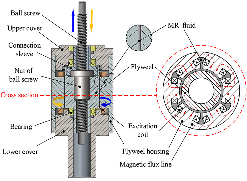
Figure 1. Structural principle of the SAI.
Mathematical Model of the SAI
Mechanical Model
Figures 2A,B are the ideal models for the conventional inerter and the SAI, respectively. The inertance and the output force of the conventional ball screw type inerter can be expressed as:
where b is the inertance of the inerter; Fb is the output force of the conventional inerter; J is the moment of inertia of the flywheel; p is the lead of the screw shaft of the ball screw; and x1 and x2 are the displacements at the two ends of the inerter.
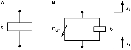
Figure 2. Ideal model: (A) the conventional inerter and (B) the SAI.
According to equations (1) and (2), the ideal model of the conventional ball screw-type inerter is only related to the characteristics of the flywheel and the ball screw. The output force of the proposed SAI is dependent on the controllable force due to the viscosity change of the MR fluid. It can be expressed as:
where F is the output force of the SAI; FMR is the controllable force due to the viscosity change of the MR fluid.
FMR is expressed as:
where Tvis is the viscous torque produced by the MR fluid in field-off state (i.e., no applied current in the excitation coils) and TMR is the field-dependent torque. Tvis and TMR are respectively given by:
where η is the viscosity of the MR fluid in field-off state; τy is the shear yield stress of the MR fluid; R1 is the outer radius of the flywheel; R2 is the inner radius of the flywheel housing; nd is the rotational speed of the flywheel; sd is the width of the annular gap; Ld is the axial length of the flywheel; δ is the correction coefficient with consideration of the influence of the magnetic leakage and ξ is the coefficient of the effective area (i.e., the ratio of the effective area to the ideal area) (Bai et al., 2018).
Equivalent Inertance
The inertance is defined by the ratio of the output force of the inerter to the relative acceleration between its two ends. That is, the corresponding inertance can be obtained by the relationship between the output force and the relative acceleration of the inerter. The output force of the proposed SAI is controllable and related to the applied current. When under a certain relative acceleration, the desired inertance can be achieved by adjusting the applied current. The inertance obtained by adjusting the applied current is defined as the equivalent inertance b′ in this study.
Practically, the movement of the inerter should overcome a certain amount of inherent friction. Therefore, the output force F of the SAI in equation (3) and the equivalent inertance b′ can be rewritten as:
where f is the inherent friction force of the SAI and Δa is the relative acceleration at the two ends of the SAI.
Results, Analyses and Insights
Controllable Force Performance of the SAI
The prototype of the SAI is fabricated to verify the objective mechanical properties. As shown in Figure 3, an experimental setup based on the servo hydraulic test equipment (Type: LFH-LFV3068, SAGINOMIYA Inc.) is established to test the mechanical properties of the SAI.
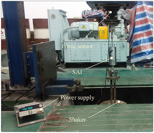
Figure 3. Experimental setup for the SAI.
Figures 4A,B show the comparisons between the theoretical and the experimental results of the mechanical response of the SAI, when a 0.5 A excitation current and sinusoidal displacement excitations with a frequency of 0.25 Hz and the excitation amplitudes of 10 mm and 20 mm are applied, respectively. As shown in Figure 4A, the theoretical value of the output force of the SAI is larger than the experimental results. When the direction of the force changes, the experimental result presents a certain hysteresis and slight fluctuations. The generated hysteresis is due to the MR effect and the gap between the mechanical structures, including the gap between the screw and the nut and the gap between the SAI and the mounting fixture. The reason for the slight fluctuations is the elastic effect of the ball screw itself. Comparing Figures 4A,B, when the amplitudes of the displacement excitations are different, the output forces of the SAI are substantially the same, indicating that the amplitude of the displacement excitation exerts little influence on the output force of the SAI.
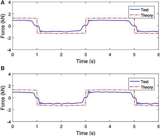
Figure 4. When the applied current is 0.5 A, the output force of the SAI under sinusoidal displacement excitations with a frequency of 0.25 Hz and different amplitudes: (A) 10 mm and (B) 20 mm.
Figures 5A,B show the comparisons between the theoretical and the experimental results of the mechanical response of the SAI, when a 0.5 A current and sinusoidal displacement excitations with an amplitude of 20 mm and the different excitation frequencies of 0.5 Hz and 1.0 Hz are applied, respectively. As shown in Figure 5A, the theoretical value of the output force of the SAI is larger than the experimental value, but the peak experimental value is slightly larger than the theoretical one due to the elastic effect of the ball screw. Comparing Figures 5A,B, when the frequency of the displacement excitation is different, the output force of the SAI is almost constant, which indicates that the frequency of the displacement excitation has little effect on the output force of the SAI. However, the fluctuation phenomenon becomes more apparent as the frequency of the displacement excitation increases.
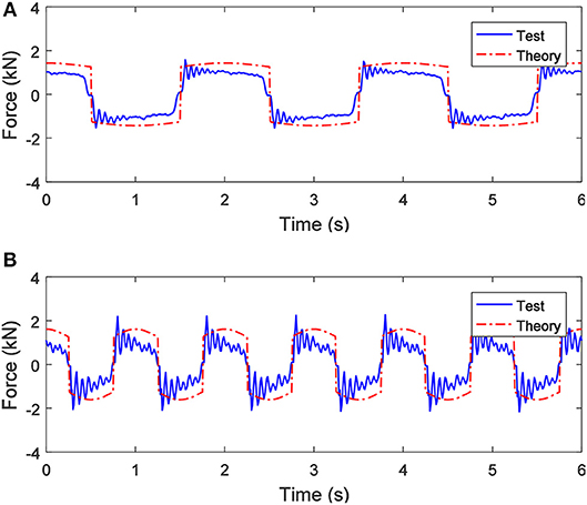
Figure 5. When the applied current is 0.5 A, the output force of the SAI under sinusoidal displacement excitations with an amplitude of 20 mm and different frequencies: (A) 0.5 Hz and (B) 1.0 Hz.
Figures 6A,B show the comparisons between the theoretical and the experimental results of the mechanical response of the SAI, when 0 A and 1.0 A currents and a sinusoidal displacement excitation with a frequency of 1.0 Hz and an amplitude of 20 mm are applied, respectively. As shown in Figure 6A, the theoretical value of the output force is basically the same as the change trend of the experimental result, but the fluctuation of the experimental result is obvious and covers almost the entire cycle of the motion. Comparing Figures 6A,B, the output force of the SAI is obviously affected by the applied current and increases with the increase of the applied current. Besides, the larger the applied current is, the larger the difference between the theoretical and the experimental results.
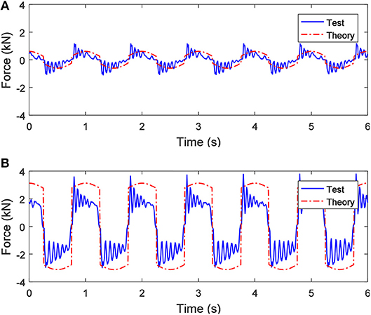
Figure 6. When the applied current is different, the output force of the SAI under a sinusoidal displacement excitation with a frequency of 1.0 Hz and an amplitude of 20 mm: (A) 0 A and (B) 1.0 A.
Based on the comparison of Figures 4–6, when under different amplitudes and frequencies of sinusoidal displacement excitations (i.e., the different excitation speeds), the maximal output force of the SAI is nearly unchanged, which is because of the pure shear working mode of the MR fluid in the SAI.
Nonlinear Realization of the SAI
As shown in Figures 4–6, as the frequency of the sinusoidal displacement excitation increases, the fluctuation of the experimental result of the SAI increases, and the difference between the experimental and the theoretical values expands. Therefore, it can be deduced that the mechanical performance of the SAI is affected by nonlinear factors. The nonlinear factors affecting the output force of the SAI are mainly derived from the gap and the elastic effect of the ball screw and the inherent friction force, including the friction between the screw and the nut and the friction inside the bearing. The gap of the ball screw could be eliminated by preloading, so the effect of the gap will not be taken into account when establishing the nonlinear model. Figure 7 shows the nonlinear model of the SAI containing inherent friction force and the elastic effects of the ball screw (Wang and Su, 2008).
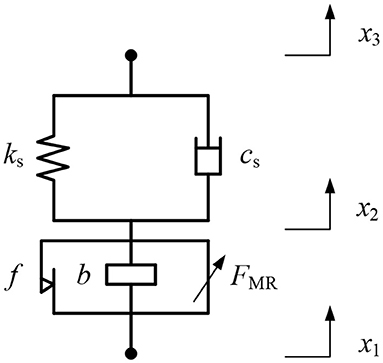
Figure 7. Nonlinear model of the SAI.
In the experimental tests, one end of the SAI is fixed, as shown in Figure 3, so x3 = 0. According to Figure 7, the dynamic model of the SAI with nonlinearities is expressed by:
where ks and cs are the stiffness and damping of the ball screw, respectively.
The minimal inertance of the proposed SAI is set to 600 kg (i.e., the inherent inertance is 600 kg when the applied current is 0 A). When the SAI is excited by sinusoidal displacement excitations with low frequencies and no current is applied, the output force is dominated by the inherent friction force, and the inertia of the flywheel can be ignored. In this case, the output force of the SAI can be approximately regarded as the inherent friction force. In this study, a sinusoidal displacement excitation with a frequency of 0.1 Hz and an amplitude of 10 mm is applied to the SAI in field-off state and the inherent friction force f of the SAI is about 310 N.
Parameter identification of the nonlinear model of the SAI is conducted using experimental data under different operating conditions. The parameters ks, cs and FMR are selected to be identified using the following criterion function with the least square method:
where fth is the predicted value of the output force calculated by the nonlinear model of the SAI and fexp is the experimental value of the output force of the SAI.
The stiffness ks of the ball screw is 5,500 kN/m and the damping cs is 7,000 Ns/m according to the parameter identification. The controllable force FMR changes with the applied current, which is consistent with the actual situation. Figure 8 shows the comparison of the predicted value with the experimental value of the output force under the sinusoidal displacement excitation with an amplitude of 20 mm and a frequency of 1.0 Hz when the applied current is 0.5 A. It can be seen from Figure 8 that the predicted value of the output force agrees well with the experimental value. The effectiveness of the established nonlinear model of the SAI is therefore verified.
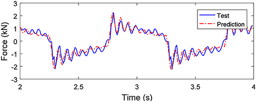
Figure 8. Comparison between the experimental and predicted results when under a sinusoidal displacement excitation with an amplitude of 20 mm and a frequency of 1.0 Hz and a 0.5 A applied current.
The established nonlinear model of the SAI can be used to achieve adjustment of the inertance. The SAI is separately subjected to an adjustment simulation of the 0–6,000 kg inertance under the condition of the lower and upper bound force (about 0–4 kN according to the test results) of the SAI. Figure 9 shows the simulation results under a sinusoidal displacement excitation with an amplitude of 20 mm and a frequency of 1.0 Hz when the expected inertance is from 0 to 6,000 kg. Since the friction factor must be considered, the inherent friction force is set to 0 N and 50 N, respectively. As shown in Figure 9, when the inherent friction force is 0 N, the adjustment of the equivalent inertance exhibits a segmented characteristic due to the existence of the phase difference between the velocity and the acceleration. The continuous adjustment of the equivalent inertance can be achieved when the controllable force works. When the controllable force fails, the equivalent inertance oscillates. In addition, both the output force and the controllable force of the SAI fluctuate at the corresponding positions, and the fluctuations are more intense as the equivalent inertance increases. When the friction force is 50 N, the fluctuation of the equivalent inertance is more obvious than that of the friction force of 0 N, but the influence on the controllable force and the output force is not very large.
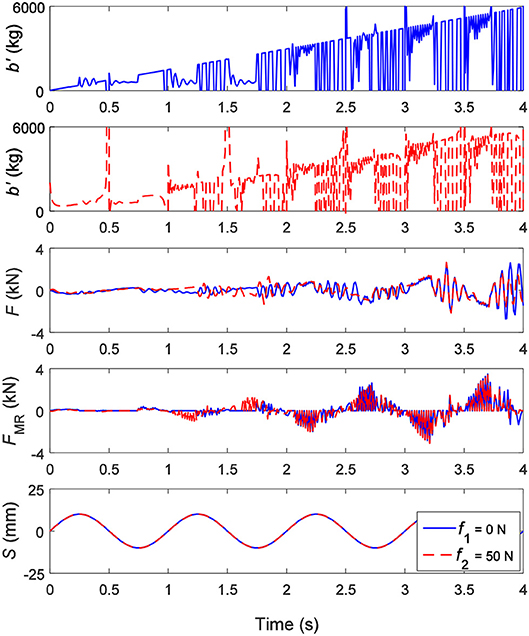
Figure 9. The equivalent inertance b′, the output force F, the controllable force FMR under a sinusoidal displacement excitation S with an amplitude of 20 mm and a frequency of 1.0 Hz when the expected inertance is from 0 kg to 6,000 kg.
Continuous Inertance Adjustment of the SAI
The output force (inertance) of the SAI is related to the acceleration, while the controllable force is related to the velocity (according to Equations 4, 5). There is a 90° phase difference between the output force and the controllable force of the SAI, which may result in failure to achieve the desired inertance when adjusting the controllable force. However, the continuous adjustment of the equivalent inertance would be achieved if a force compensator (i.e., phase adjustment mechanism) could be provided.
The SAI with a compensator is proposed and shown in Figure 10. As shown in Figure 10, the compensator is composed of a semi-active damper in series with the rack pinion mechanism and in parallel with the SAI. Taking the case under sinusoidal displacement excitation as an example, the adjustment principle of the equivalent inertance is shown in Figure 11. It can be seen from the areas ① and ② in Figure 11 that the output force of the SAI cannot be continuously adjusted due to the phase difference between the relative velocity and the relative acceleration. The area ③ shows that the force generated by the compensator is always opposite to the direction of the controllable force, so that the controllable force that could not be achieved is compensated. As shown in the area ④, the output force of the SAI can be continuously adjusted to achieve continuous adjustment of the equivalent inertance.
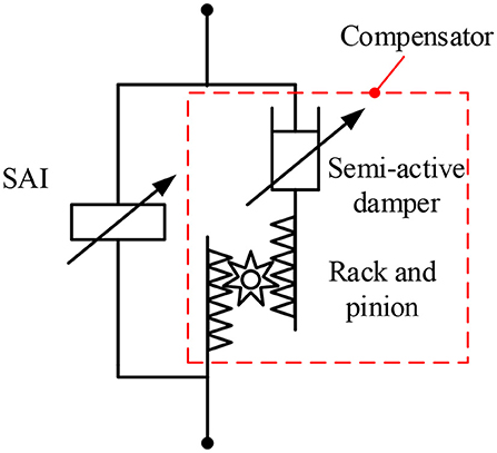
Figure 10. Schematic of the SAI with a compensator.
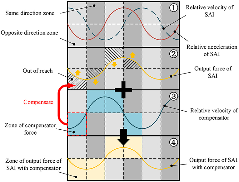
Figure 11. Adjustment principle of the equivalent inertance.
The output force of the SAI with a compensator can be expressed as:
where Fcom is the force generated by the compensator.
Figure 12 presents the simulation results under a sinusoidal displacement excitation with an amplitude of 20 mm and a frequency of 1.0 Hz when the expected inertance of the SAI with a compensator is from 0 to 6,000 kg. Since the friction could be offset by the compensator, the contrast under different inherent friction forces is not considered. It can be seen from Figure 12 that the continuous and steady adjustment of 0–6,000 kg of the equivalent inertance can be achieved. The controllable force, the force generated by the compensator and the output force produce fluctuations, and the fluctuations are more intense as the equivalent inertance increases. This is similar to the case whereby there is no compensator, as with Figure 9.
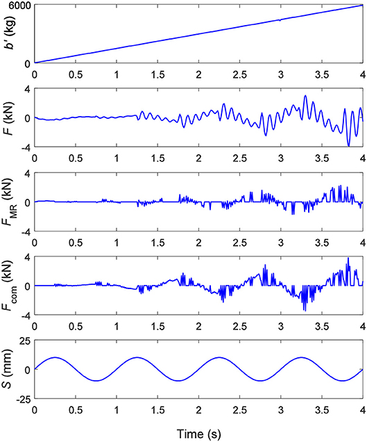
Figure 12. The equivalent inertance b′, the output force F, the controllable force FMR and the generated force of the compensator Fcom under a sinusoidal displacement excitation S with an amplitude of 20 mm and a frequency of 1.0 Hz when the expected inertance of the SAI with a compensator is from 0 kg to 6,000 kg.
An Application Case
The equivalent inertance of the ball screw-type SAI, as shown in Figure 9, is segmented, and the inherent friction of the ball screw set will influence the controllability. To study the influence of the segmented equivalent inertance of the SAI and the inherent friction force on the vibration control, a single-degree-of-freedom vibration control system as shown in Figure 13 is established. The system model is given by:
where z1 is the input displacement of the payload m; z2 is the displacement of the payload m; k is the stiffness of the spring and c is the damping of the passive damper.
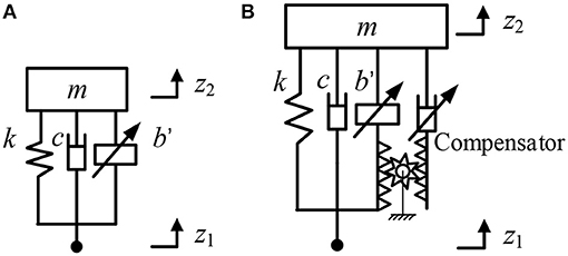
Figure 13. A single-degree-of-freedom vibration control system with a SAI: (A) with no compensator and (B) with a compensator.
Figure 14 shows the acceleration response of the system under a sinusoidal displacement excitation with an amplitude of 50 mm and a frequency of 1.0 Hz (the resonant frequency of the passive spring-mass-damper system). The payload m, the stiffness k, and the damping c are 557 kg, 22 kN/m and 1,500 Ns/m, respectively. The inherent friction force is set as: f1 = 310 N, f2 = 110 N and f3 = 10 N when the SAI has no compensator. As shown in Figure 14, the single-degree-of-freedom vibration system with the SAI has an over 4 times smaller acceleration amplitude than the conventional vibration system (i.e., the spring-mass-damper system). When the SAI is not connected to the compensator, the acceleration fluctuates due to the inherent friction force. The greater the inherent friction force, the more serious the fluctuation of the acceleration will be. However, the acceleration is still much smaller than the conventional vibration system. The acceleration of the payload of the system when the friction is 10 N basically agrees with the system with a compensator. In other words, the segmented equivalent inertance of the SAI will not influence the control performance of the SAI-based vibration control very much. This is similar to the analysis in reference (Wang and Su, 2008); the friction force of the inerter does have an adverse effect on the vibration control performance, but when the stiffness of the suspension is great, the overall performance of the system using the inerter with friction force is still superior to the conventional ones.
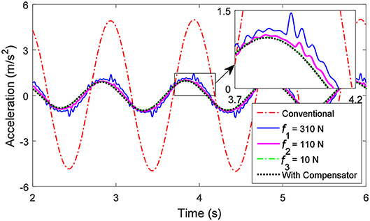
Figure 14. Acceleration response of the single-degree-of-freedom vibration system under a sinusoidal displacement excitation with an amplitude of 50 mm and a frequency of 1.0 Hz.
Conclusions
In order to enhance the performance of the conventional passive inerter, the structural principle of an SAI was proposed and studied in this paper. It is composed of a flywheel, a flywheel housing, a ball screw, a connection sleeve, bearings, upper, and lower covers, excitation coils, and MR fluid. The proposed SAI achieves adjustment of the inertance by adjusting the applied current in the excitation coils and has the advantages of a simple structure and wide adjustable range. The mathematical model of the SAI was established and the mechanical properties of the SAI were tested based on the experimental setup. The test results indicate that the nonlinear factors of the ball screw cannot be ignored for mechanical performance description of the SAI. A nonlinear model of the SAI was established and the parameters were identified by the least squares method. The continuous adjustment of the equivalent inertance was realized by integrating a compensator to overcome the phase difference between the controllable force and the output force. Vibration attenuation performances of a single-degree-of-freedom vibration system based on the SAI with and without a compensator, as a very preliminary application case, are analyzed and compared. Based on the research of this paper, the conclusions are summarized as follows.
(i) The established nonlinear model of the SAI can effectively describe and predict the mechanical properties of the SAI.
(ii) The problem of the phase difference between the controllable force and the output force can be solved via a compensator. The continuous adjustment of an equivalent inertance with a range of 0–6000 kg could be achieved by adjusting the applied current. The proposed and employed compensator presents a helpful approach for the phase control of force in mechanical systems.
(iii) For a single-degree-of-freedom vibration system, the SAI with no compensator still provides a better vibration isolation performance than the conventional system, and the smaller the inherent friction force is, the better the performance will be.
Author Contributions
W-MZ carried out the modeling, computation and experimental work, and helped draft the manuscript. X-XB conceived the conception, investigated the technical background, designed, and coordinated the study, and drafted and revised the manuscript. CT helped do modeling and experimental work and draft the manuscript. A-DZ helped draft and revise the manuscript.
Conflict of Interest Statement
The authors declare that the research was conducted in the absence of any commercial or financial relationships that could be construed as a potential conflict of interest.
Acknowledgments
The authors wish to acknowledge the Key Research and Development Projects of Anhui Province (Grant No. 1704E1002211) for her support of this research.
References
Bai, X. X., Zhong, W. M., Zou, Q., Zhu, A. D., and Sun, J. (2018). Principle, design and validation of a power-generated magnetorheological energy absorber with velocity self-sensing capability. Smart Mater. Struct. 27:075041. doi: 10.1088/1361-665X/aac7ef
Chen, M. Z. Q., Papageorgiou, C., Scheibe, F., Wang, F. C., and Smith, M. C. (2009). The missing mechanical circuit element. IEEE Circuits Syst. Magazine 9:1. doi: 10.1109/MCAS.2008.931738
Chen, P., Bai, X. X., and Qian, L. J. (2016). Magnetorheological fluid behavior in high-frequency oscillatory squeeze mode: experimental tests and modelling. J. Appl. Phys. 119:105101. doi: 10.1063/1.4943168
Chen, P., Bai, X. X., Qian, L. J., and Choi, S. B. (2018). An approach for hysteresis modeling based on shape function and memory mechanism. IEEE/ASME Transact. Mechatro. 23, 1270–1278. doi: 10.1109/TMECH.2018.2833459
Chen, P., Qian, L. J., Bai, X. X., and Choi, S. B. (2017). Velocity-dependent characteristics of magnetorheological fluids in squeeze mode considering the hydrodynamic and the magnetic field interactions. J. Rheol. 61, 455–465. doi: 10.1122/1.4978594
Giaralis, A., and Peteini, F. (2017). Wind-induced vibration mitigation in tall buildings using the tuned mass-damper-inerter. J. Struct. Eng. 143:04017127. doi: 10.1061/(ASCE)ST.1943-541X.0001863
Hu, Y., Chen, M. Z. Q., Xu, S., and Liu, Y. (2017). Semiactive inerter and its application in adaptive tuned vibration absorbers. IEEE Transact. Control Syst. Technol. 25, 294–300. doi: 10.1109/TCST.2016.2552460
Papageorgiou, C., Lockwood, O. G., Houghton, N. E., and Smith, M. C. (2007). “Experimental testing and modelling of a passive mechanical steering compensator for high-performance motorcycles,” in Control Conference (ECC) (European, IEEE), 3592–3599. doi: 10.23919/ECC.2007.7068739
Shen, Y., Chen, L., Yang, X., Shi, D., and Yang, J. (2016). Improved design of dynamic vibration absorber by using the inerter and its application in vehicle suspension. J. Sound Vibrat. 361, 148–158. doi: 10.1016/j.jsv.2015.06.045
Smith, M. C. (2002). Synthesis of mechanical networks: the inerter. IEEE Transact. Automat. Control 47, 1648–1662. doi: 10.1109/TAC.2002.803532
Smith, M. C. (2008). Force-Controlling Mechanical Device. U.S. Patent 7, 316–303. US 2005/0034943 A1.
Swift, S. J., Smith, M. C., Glover, A. R., Papageorgiou, C., Gartner, B., et al. (2013). Design and modelling of a fluid inerter. Int. J. Control 86, 2035–2051. doi: 10.1080/00207179.2013.842263
Tang, X., Zhang, X., Tao, R., and Rong, Y. (2000). Structure-enhanced yield stress of magnetorheological fluids. J. Appl. Phys. 87, 2634–2638. doi: 10.1063/1.372229
Tipuric, M., Deastra, P., Wagg, D., and Sims, N. (2018). “Semi-active inerters using magnetorheological fluid: a feasibility study,” in Active and Passive Smart Structures and Integrated Systems, X. I. I. (Denver, CO), 10595.
Wang, F. C., Hong, M. F., and Lin, T. C. (2011). Designing and testing a hydraulic inerter. Proceedings of the institution of mechanical engineers, Part, C. J. Mech. Eng. Sci. 225, 66–72. doi: 10.1243/09544062JMES2199
Wang, F. C., Liao, M. K., Liao, B. H., Su, W. J., and Chan, H. A. (2009). The performance improvements of train suspension systems with mechanical networks employing inerters. Vehicle Syst. Dynam. 47, 805–830. doi: 10.1080/00423110802385951
Wang, F. C., and Su, W. J. (2008). Impact of inerter nonlinearities on vehicle suspension control. Vehicle Syst. Dynam. 46, 575–595. doi: 10.1080/00423110701519031
Yu, P. (2015). Study on Some Key Technologies of Suspension Changeable Inerter. Master Thesis of Zhejiang University, Hangzhou, China.
Keywords: semi-active inerter, magnetorheological (MR) effect, magnetorheological (MR) fluids, continuously tunable inertance, nonlinearity
Citation: Zhong W-M, Bai X-X, Tang C and Zhu A-D (2019) Principle Study of a Semi-active Inerter Featuring Magnetorheological Effect. Front. Mater. 6:17. doi: 10.3389/fmats.2019.00017
Received: 30 October 2018; Accepted: 28 January 2019;
Published: 19 February 2019.
Edited by:
Seung-Bok Choi, Inha University, South KoreaReviewed by:
Xiaomin Dong, Chongqing University, ChinaXufeng Dong, Dalian University of Technology (DUT), China
JinHyeong Yoo, Naval Surface Warfare Center Carderock Division, United States
Copyright © 2019 Zhong, Bai, Tang and Zhu. This is an open-access article distributed under the terms of the Creative Commons Attribution License (CC BY). The use, distribution or reproduction in other forums is permitted, provided the original author(s) and the copyright owner(s) are credited and that the original publication in this journal is cited, in accordance with accepted academic practice. No use, distribution or reproduction is permitted which does not comply with these terms.
*Correspondence: Xian-Xu Bai, YmFpQGhmdXQuZWR1LmNu; www.lasiser.com