 Han Gyeol Gang1
 Seung-Bok Choi
 Jung Woo Sohn
- 1Department of Mechanical Design Engineering, Kumoh National Institute of Technology, Gumi, South Korea
- 2Department of Mechanical Engineering, Inha University, Incheon, South Korea
In this work, a new type of haptic system inspired by human wrist motion is proposed, and its performance is evaluated experimentally for teleoperation. The master device has 3-DOF rotational motion, which is the same as human wrist motion; semi-active magnetorheological brakes are installed to generate a haptic effect for the operator. To achieve a good haptic feedback effect, the master device is designed with a lightweight structure and the haptic actuator is designed with minimal size. The slave robot has 3-DOF rotational motion using servomotors, a five-bar linkage mechanism, and a pivot point. In the proposed slave robot, instead of a commercial torque sensor, a newly designed torque sensor that uses three force sensors is adopted. It is experimentally validated that the proposed haptic system has good performance in terms of the tracking control of the desired position and repulsive torque. In addition, to ensure that the human operator can actually distinguish the different magnitudes of torque, a simple recognition test is carried out. Although not continuous, it is confirmed that the torque difference can be distinguished at three levels. Finally, it is demonstrated that the proposed haptic system can be effectively applied to a real teleoperation system.
Introduction
A teleoperation control system that uses a master device to control a slave robot has several advantages, for example, the worker is not restricted to the worksite environment and can perform precise work such as robotic surgery. Many research studies have been carried out in order to utilize teleoperation in various fields, such as the space industry and nuclear energy industry. Recently, a system that can be applied to surgical operations that utilizes a master device-slave robot system has been developed, and research on a surgical robot system represented by Da Vinci has been actively conducted. Instead of conventional laparotomy, robot surgery involves insertion of a robotic arm into the body through three or four small holes in the body, and the operation then proceeds. Robotic surgery is expected to expand gradually, despite the high cost, because it has several advantages, such as a small surgical wound, low risk of infection, and quick recovery. Currently, the biggest disadvantage of a remote-control system, that uses the master-slave system, is that the operator relies solely on visual and auditory information without tactile information which decreases the worker's sense of realism and immersion. In order to compensate for this, various haptic systems that are capable of transmitting tactile information to the operator, are being studied. Many researches on haptic systems using electric motors have been proposed. When an electric motor is used as a haptic actuator, a decelerator that uses gears and an encoder for position measurement are used together, which leads to the disadvantage of the system becoming bulky and difficult to control. In recent years, studies on haptic actuators using smart materials such as piezoelectric materials, electrorheological and magnetorheological (MR) fluids, and electro-active polymers have been actively conducted. A smart material is a material that can change its characteristics according to changes in the external environment, and a system using it can take advantage of this to generate an operating force directly without additional mechanical devices. A MR fluid, that can change its viscosity according to changes in the external magnetic field strength, is composed of a suspension of silicone oil and iron particles. The merits of MR fluid are that they have a fast response time, low energy consumption, and simple system configuration. Representative mechanical devices that apply MR fluid include automotive MR dampers, MR mounts and MR clutches/brakes. It has been confirmed that dampers and mounts that use MR fluid have better performance than the existing passive devices, and they have been commercialized and mounted on various advanced vehicles (Wang and Liao, 2011). A MR clutch/brake has the capability of reducing or stopping the rotational speed of a shaft using the MR effect, which is generated between the rotor and stator. Many studies are currently underway to improve the performance of MR brakes and to apply them to various fields. Imaduddin et al. reviewed the design of MR brakes and the characteristics of each type of MR brake, such as drum-type, disc-type, and hybrid-type, were identified and mathematical modeling techniques were discussed in detail (Imaduddin et al., 2013). Nguyen and Choi investigated the optimal design of different types of MR brake to achieve a high torque output under a constrained specific volume (Nguyen and Choi, 2012b). Sohn et al. optimized the design parameters of a disc-type MR brake for a mid-sized motorcycle, and the mechanical characteristics, such as response time and braking torque, were experimentally evaluated (Sohn et al., 2015). Wu et al. designed a new type of MR brake with a multi-pole and dual-gap configuration to increase the range of the output torque while maintaining a compact structure (Wu et al., 2016). Recently, various researches have been carried out to utilize MR brakes as haptic actuators. Liu et al. reported the design, testing, and modeling of a MR fluid brake and demonstrated example applications of a MR brake as a haptic actuator for a virtual reality hardware (Liu et al., 2006). Li et al. presented the design and development of a MR fluid-based haptic system and demonstrated the applications of a MR joystick for virtual reality by using four typical 2D and 3D interface examples (Li et al., 2007). An and Kwon proposed a five-bar linkage haptic device featuring DC motors and MR brakes, and it was demonstrated that the combination of DC motors and MR brakes has a broader Z-width than that of solely DC motors (An and Kwon, 2009). Senkal and Gurocak proposed a design of an MR spherical brake as a multi-DOF actuator for a joystick-type haptic application (Senkal and Gurocak, 2009). They identified virtual wall collision, damping, and Coulomb friction simulations via experiments. Nguyen and Choi proposed an optimal design of a bi-directional MR brake for a haptic system for surgical robot applications (Nguyen and Choi, 2012a). The suggested bi-directional MR brake can transmit generated active and semi-active braking torque. Nguyen and Choi also experimentally evaluated the control performance of a bi-directional MR clutch by considering hysteresis and friction effects (Nguyen and Choi, 2013). In recent years, MR brakes have been developed that can generate the sufficient required operating torque despite having a compact size. Nguyen et al. proposed a new configuration of a 3D haptic gripper for tele-manipulation and optimal design was conducted (Nguyen et al., 2013). Sohn et al. designed a new type of MR brake that increases the area where the MR effect is generated by modifying the shape of the magnetic core and experimentally validated the effectiveness of the proposed MR brake by comparing it with a conventional MR brake (Sohn et al., 2018).
The main contribution of this work is the design and experimental evaluation of a simple and low-cost haptic system that consists of a master device and slave robot. Due to considerations of real system applications, the 3-DOF master device was designed with a lightweight structure that can be driven in the same way as the motion of the human wrist. A minimized haptic actuator was also designed using a MR brake and installed to the master device. In order to obtain a large torque, a multi-disc type MR brake can be considered. However, since the size of the actuator becomes large, it cannot be applied to this work. In this study, a drum type brake was used and a dual magnetic core was applied to obtain a large torque at a small size. The motion of the master device was measured by using a chip-type MEMS gyro sensor, which is embedded in the master device. The slave robot, which can realize 3-DOF rotational motion, was designed using a five-bar linkage mechanism and servomotors. In order to measure the position of the slave robot, a gyro sensor, the same as the sensor that is installed in the master device, was used. Instead of a commercial force or torque sensor, a new type of torque sensor was fabricated and adopted for the slave robot to monitor its status. After realization of a fuzzy-PID control algorithm, the performance characteristics of the proposed haptic system were evaluated via experiments and good control performances were achieved in position tracking control of the slave robot and repulsive torque tracking control of the master device. Additionally, to ensure that the human operator can actually distinguish the different magnitudes of torque, a simple recognition test was also conducted.
Components Design
MR Brake
MR fluid is a type of smart fluid whose viscosity can be controlled by applying an external magnetic field. Typically, MR fluid is a suspension of carrier oil and micrometer-scale magnetic particles. When MR fluid is subjected to a magnetic field, the magnetic particles construct a chain structure by aligning themselves along the direction of the magnetic flux. The yield stress of the MR fluid is obtained from the breaking force of this chain structure. Since the bonding force of the chain structure depends on the strength of the applied magnetic field, the yield stress of the MR fluid can be continuously controlled by controlling this. In this work, a commercial MR fluid, MRF-132DG of Lord Corp. is used in the proposed MR brake of the master device. The basic material properties are summarized in Table 1 and as a magnetic property of the MR fluid, the relationship between magnetic flux density and magnetic field intensity is presented in Figure 1A. In addition, the relationship between the shear stress and magnetic field intensity of the MR fluid is presented in Figure 1B. The yield stress of the MR fluid, τ, can be expressed as follows by using the Bingham plastic model:
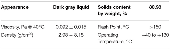
Table 1. Material properties of MRF-132DG.
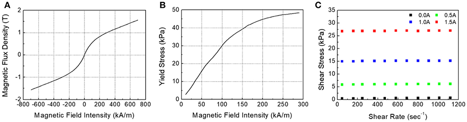
Figure 1. Material characteristics of MRF-132DG. (A) Magnetic property, magnetic flux density vs. magnetic field intensity. (B) Yield stress vs. magnetic field intensity. (C) Shear stress vs. shear rate according to applied current.
Where τy(B) is the magnetic flux density-dependent yield stress, η is the viscosity of the MR fluid without a magnetic field, and is the shear strain rate. Then, the relationship between the shear stress and magnetic flux density of the MR fluid can be determined by the following equation.
The mechanical property, the relationship between shear stress and shear rate, is measured according to the input current by using a viscometer and the results are presented in Figure 1C. It can be clearly observed that the shear stress of the MR fluid increases as the intensity of the applied magnetic field increases.
In order to achieve a high actuating torque that satisfies the design constraints of a small-sized actuator, a drum-type MR brake with a dual magnetic core shape is designed and fabricated in this work. The exploded view of the proposed MR brake is presented in Figure 2A. The proposed MR brake consists of a stator, magnetic core, rotor, shaft, outer case, upper case, and lower case. The copper wire is wound on the magnetic core without bobbin to generate a magnetic field. The MR fluid is filled in the gap between the rotor and stator. The MR effect, which is a torque resistant to the rotation of the rotor, can be achieved by generating a magnetic field across the rotor and stator. A section view with geometrical dimensions is presented in Figure 2B. The outer radius of the proposed MR brake is 25 mm, which is similar to the size of a slim beverage can. The height and gap size are 54 and 1 mm, respectively. A photograph of the manufactured MR brake is presented in Figure 2C. The total magnitude of the braking torque of the MR brake can be estimated from the following equation.
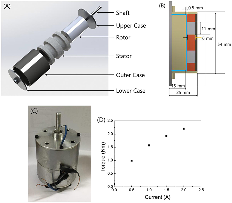
Figure 2. The proposed MR brake. (A) Configuration. (B) Section view. (C) Photograph. (D) Measured torque.
Where TMR is the controllable toque from the MR effect, Tη is the torque generated from the viscosity of the MR fluid, and Tf is the torque generated from the mechanical friction of the device. The controllable torque, TMR, is expressed as a function of the yield stress of the MR fluid by the following equation.
Where d is the total length of the area where a magnetic force is generated in the gap and R is the radius of the rotor. The torque generating performance of the manufactured MR brake is experimentally evaluated and the results are shown in Figure 2D. The maximum torque is 2.2 Nm at an input current of 2 A, and that is enough to prevent rotational motion with the human hand.
Master Device
A photograph of the manufactured master device is shown in Figure 3. In order to realize human wrist motion exactly, the three axes of 3-DOF rotation meet at a point on the proposed master device. In addition, it is important for the master device to provide a precise reaction force or resistance torque, so it is important to design the device as a lightweight structure. For the proposed master device, the structural weight is reduced by applying an aluminum frame, and the haptic actuator is also manufactured in a small size. The weight of each element of the master device is shown in Table 2. The total weight of the moving part is about 1,600 g, including two MR brakes. To reduce the operator's work fatigue, a power grip that uses a stick instead of a finger grip is applied. Three MR brakes are installed on each rotary axis to produce a resistance torque for each of the three rotary directions. The MR brakes generating the torque in the pitch and roll directions are mounted to the master device frame and the MR brake generating the torque in the yaw direction is mounted on the base to reduce the weight of the master device. There are many studies that use electric motors as haptic actuators. In this case, reducers and encoders are indispensable. However, the use of MR brakes reduces the complexity and weight of the system by eliminating the need for a gear reducer, that is essential when using an electric motor. The braking force is transmitted without loss due to backlash while the actuator is directly engaged with the instrument so that the transmissibility of the haptic effect can be improved. In addition, in the proposed master device, a chip-type MEMS gyro sensor (Model MPU9250, InvenSense) is inserted into the grip stick without using an encoder on the rotating shaft, and the rotation angle is measured so that the position of the master device can be transmitted to the slave robot.
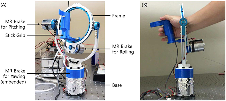
Figure 3. Photograph of the manufactured master device. (A) Front view. (B) Side view.
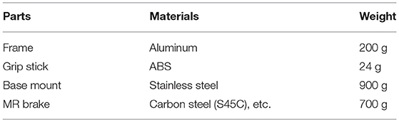
Table 2. Components of the MR Brake and their weights.
Slave Robot
The structural configuration and a photograph of the manufactured slave robot are presented in Figures 4A,B respectively. In order to enhance intuitive usability, the slave robot is designed to be able to rotate in 3-DOF to correspond to the degrees of freedom of the master device. The slave robot is based on the manipulator type used in robot surgery, and the diameter of the arm is designed to be less than 2 mm in consideration of practical usability. The proposed slave robot is able to generate pitch and yaw motions using two servomotors, a five-bar linkage mechanism with planar motion, and a pivot point. The roll motion is generated using a separate servo motor. A schematic diagram of the slave robot for calculating the angle to be generated in the servo motor is shown in Figure 5. Since a pivot point is used in the proposed slave robot, the position of the slave robot end effector in the pitch and yaw directions is determined by the position of joint P of the five-bar linkage. The position of joint P can be expressed by the following equation.
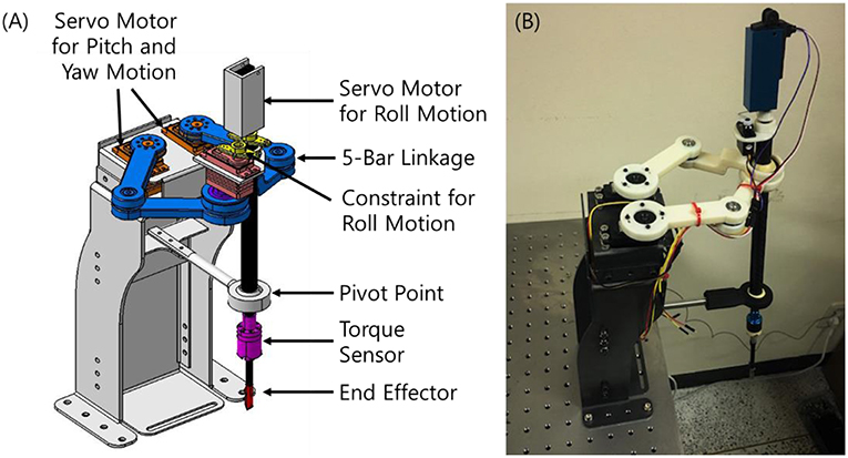
Figure 4. The proposed slave robot. (A) Structural configuration. (B) Photograph.
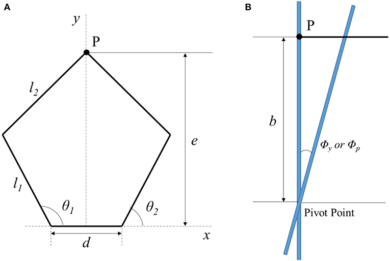
Figure 5. Configuration for slave robot position determination. (A) Top view. (B) Side view.
Where b is the length of the robot manipulator from the five-bar linkage to the pivot point, Φy is the desired input angle in the yaw direction, Φp is the desired input angle in the pitch direction, d is the length of fixed link and e is the distance of joint P in the y-direction from the x-axis. Finally, the required angle that should be generated by the servomotor can be calculated from the following equation.
For haptic feedback, the slave robot should be equipped with a sensor capable of measuring force or torque. However, since a general torque sensor is bulky, it is difficult to apply to the proposed slave robot. It is possible to apply this sensor temporarily for the experiment, but it is difficult to apply it in an actual use environment. In this study, a new type of sensor capable of measuring torque in three directions is proposed and applied. The structural configuration of the proposed torque sensor is presented in Figure 6. The proposed torque sensor consists of three symmetrically-arranged force sensors (Model FSS015WNSX Honeywell) and a steel ball in contact with them. The end effector of the slave robot can be inserted into one end of the proposed torque sensor, so that various end effectors capable of various operations can be utilized. If the end effector of the slave robot has a resistance force against the direction in which it is intended to operate, the steel ball is brought into contact with the force sensors and a force is generated. The resistance torque for each direction of rotation from the measurement data of the three force sensors can be calculated using the following equations.
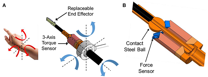
Figure 6. The proposed torque sensor. (A) Configuration. (B) Section view.
Where T is the resistance torque of the end effector, P is the resistance force of the end effector, and le is the length of the end effector. The force P can be expressed as follows using the measured forces from the three force sensors (Xu et al., 2014).
The force P can be decomposed in x, y, and z directions as follows:
Where α and β are the angles between the end effector and the slave robot rod in the x-z and x-y planes, respectively. The measured forces from the force sensors can be expressed by the following equations.
Where k1, k2, and k3 are calibration coefficients and S1, S2, and S3 are measured sensor values.
Haptic System
The configuration of the proposed haptic system is presented in Figure 7. In this study, the master system and slave robot are independently controlled through the control box without configuring the PC-based control system. UART serial communication is used between the master device and slave robot to transmit the required position and torque. The control box for the master device consists of a main processor [Model. Arduino Due (84 Mhz)], SMPS for power supply, current amplifier, and current sensor. The control box for the slave robot consists of a main processor [Model. Arduino Due (84 Mhz)], SMPS for power supply, and motor drivers for the servomotors. However, in this study, each control box and the PC are connected to be able to store measured data. Before the control experiment, the workspaces of the master device and slave robot are confirmed through experiments. The data are measured using MEMS gyro sensors attached to the master device and slave robot, and the actual wrist motion is measured by attaching the gyro sensor to the hand. The measured workspaces in the pitch and yaw directions are shown in Figure 8. Although the workspaces are slightly different, it can be seen that the workspace of the master device and the slave device effectively cover the workspace of the wrist.
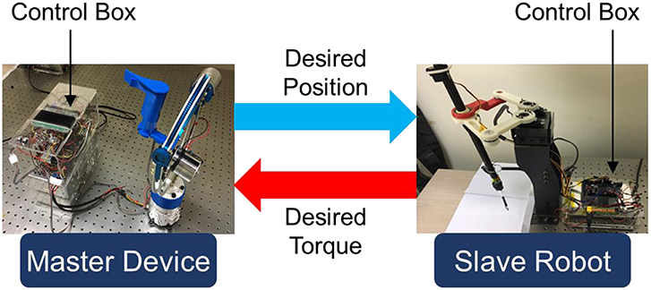
Figure 7. Schematic diagram of the proposed master-slave haptic system.
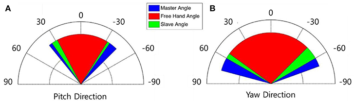
Figure 8. Comparison of the measured workspaces. (A) Pitch motion. (B) Yaw motion.
Generally, PID control has advantages of easy configuration and application. However, since the control gain cannot be continuously changed, there is a disadvantage that control performance is limited when the external environment changes. In this study, a fuzzy-PID control algorithm is applied to control the haptic system and the PID control gain is determined using a fuzzy algorithm. A block diagram of the fuzzy-PID control algorithm is shown in Figure 9. The control input of the proposed fuzzy-PID control algorithm can be expressed as follows (Ziegler and Nichols, 1942).
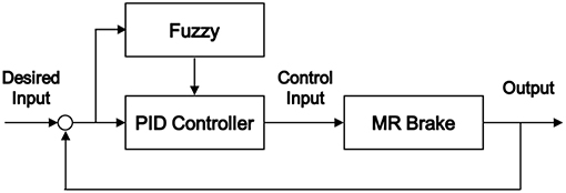
Figure 9. Block diagram of the fuzzy-PID control algorithm.
Where e(k) is the error between the reference input and actual output,Δe(k) is the rate of change of error. KP, KI, and KD are the proportional, integral, and derivative control gains, respectively. It is assumed that the ranges of KP and KD are limited as follows.
Where ku and Tu are the gain and the period of oscillation, respectively, at the stability limit under P-control. The parameters Kp′, KD′ and α are determined by a fuzzy operation with e(k) and e(k) as input values, and the control gain of the PID controller is determined from the following equations.
The input and output membership functions used in the fuzzy algorithm are shown in Figure 10. Experiments are performed to confirm the performance of the proposed slave robot at tracking the position of the master device, which is changed by the hand movements of the operator. The results are shown in Figure 11. Only the MEMS gyro sensor is used without additional sensors such as encoders. As shown in this figure, it can be seen that the slave robot keeps track of the required position measured from the master device. Experiments are conducted to confirm that the resistance torque generated from the end effector of the slave robot is transmitted to the operator through the haptic actuator of the master device. The results are shown in Figure 12. In the slave robot, the resistance torque is measured by the built-in torque sensor. In the master device, which does not include an additional torque sensor, the current value applied to the MR brake is monitored and the magnitude of the generated torque estimated using results from Figure 2D. As shown in the results of Figures 11, 12, it can be confirmed that the torque generated by the haptic actuator of the master device follows the torque generated in the slave robot substantially well. Finally, it can be concluded that the proposed low-cost haptic system has excellent control performance.
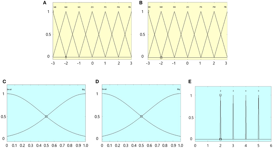
Figure 10. Membership function of the fuzzy algorithm. (A) Input e(k). (B) Input Δe(k). (C) Output KP. (D) Output KD. (E) Output α.
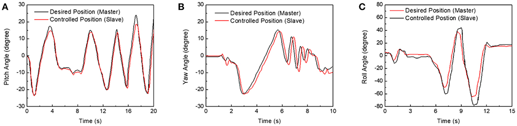
Figure 11. Position tracking control results. (A) Pitch motion. (B) Yaw motion. (C) Roll Motion.
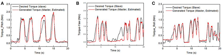
Figure 12. Repulsive torque tracking control results. (A) Pitch motion. (B) Yaw motion. (C) Roll Motion.
In order to confirm the applicability of the proposed haptic system, experiments are carried out to determine if a person can recognize the difference in resistance torque generated by the MR brake and transmitted to the user. Five different materials, including sponge, fabric, silicone, plastic barrel, and steel rod, are brought into contact with the end effector. When the end effector comes into contact with an object, a low resistance torque is generated. If a participant can freely perform the hand operation they give a score of 0. Conversely, if a participant feels that they cannot move their hand due to the large resistance torque, a score of 5 is given. Four participants performed the experiment, and they are prevented from seeing the objects they are touching to remove bias. The type of object contacting the end effector is selected at random. The results of the cognitive experiments are summarized in Table 3. From the experimental results, it can be seen that the participants could not recognize the torque value continuously, but could recognize the difference in torque transmitted in three stages. Although the experiment could have been improved by increasing the number of participants and applied objects, it is considered that it is possible for the operator of the master device to distinguish the difference in torque through several stages with the proposed MR brake-based haptic system.
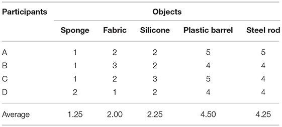
Table 3. Recognition test results.
Conclusions
In this study, a master device and slave robot, that can implement the same motion as a human wrist, have been proposed. In addition, a haptic system was constructed that can transmit the resistance torque generated when the end effector of the slave robot hits an object to the user of the master device. In order to improve the haptic effect, the master device was designed to be lightweight structure and a semi-active actuator was constructed using a miniaturized MR brake as a haptic actuator. Considering the possibility of its use in an actual system, the position tracking control of the master device and the slave robot was performed by replacing the commercial encoder, which has a large volume and weight, with a MEMS gyro sensor. In addition, a small sensor capable of measuring the torque of the slave robot was built and torque tracking control was performed. From the experimental results, it is confirmed that the proposed haptic system has a low-cost but excellent control performance. Finally, a cognitive characteristics experiment with four participants was performed and it was confirmed that the operator can distinguish between different magnitudes of torque by about three different levels using the proposed system. Generally, it takes more than 7-DOF to implement human arm and wrist motion. In this study, 3-DOF required for human wrist motion were considered and excellent experimental results were obtained. Based on these results, it is expected that it will be possible to extend the proposed system more than 7-DOF system.
Author Contributions
HG set up experimental apparatus, conducted experiments, and collected all measured data. S-BC contributed to the conception and design of the study and analyzed the experimental results. JS wrote the first draft of the manuscript. All authors contributed to manuscript revision and read and approved the submitted version.
Funding
This research was supported by the National Research Foundation (NRF) of Korea funded by Ministry of Science and ICT (NRF-2017R1C1B2012207).
Conflict of Interest Statement
The authors declare that the research was conducted in the absence of any commercial or financial relationships that could be construed as a potential conflict of interest.
References
An, J., and Kwon, D. (2009). Five-bar linkage haptic device with DC motors and MR brakes. J. Intel. Mater. Syst. Struct. 20, 97–107. doi: 10.1177/1045389X07086690
Imaduddin, F., Mazlan, S. A., and Zamzuri, H. (2013). A design and modelling review of rotary magnetorheological damper. Mater Des. 51, 575–591. doi: 10.1016/j.matdes.2013.04.042
Li, W. H., Liu, B., Kosasih, P. B., and Zhang, X. Z. (2007). A 2-DOF MR joystick for virtual reality applications. Sens. Actuat. A Phys. 137, 308–320. doi: 10.1016/j.sna.2007.03.015
Liu, B., Li, W. H., Kosasih, P. B., and Zhang, X. Z. (2006). Development of an MR-brake-based haptic device. Smart Mater. Struct. 15, 1960–1966. doi: 10.1088/0964-1726/15/6/052
Nguyen, P. B., and Choi, S. B. (2012a). A bi-directional magneto-rheological brake for medical haptic system: optimal design and experimental investigation. Adv Sci Lett. 13, 165–172. doi: 10.1166/asl.2012.3843
Nguyen, P. B., and Choi, S. B. (2013). Accurate torque control of a bi-directional magneto-rheological actuator considering hysteresis and friction effects. Smart Mater. Struct. 22:055002. doi: 10.1088/0964-1726/22/5/055002
Nguyen, Q. H., and Choi, S. B. (2012b). Selection of magnetorheological brake types via optimal design considering maximum torque and constrained volume. Smart Mater. Struct. 21:015012. doi: 10.1088/0964-1726/21/1/015012
Nguyen, Q. H., Choi, S. B., Lee, Y. S., and Han, M. S. (2013). Optimal design of a new 3D haptic gripper for telemanipulation featuring magnetorheological fluid brakes. Smart Mater. Struct. 22:015009. doi: 10.1088/0964-1726/22/1/015009
Senkal, D., and Gurocak, H. (2009). Spherical brake with MR fluid as multi degree of freedom actuator for haptics. J. Intel. Mater. Syst. Struct. 20, 2149–2160. doi: 10.1177/1045389X09348925
Sohn, J. W., Gang, H. G., and Choi, S. B. (2018). An experimental study on torque characteristics of magnetorheological brake with modified magnetic core shape. Adv. Mech. Eng. 10, 1–10. doi: 10.1177/1687814017752222
Sohn, J. W., Jeon, J., Nguyen, Q. H., and Choi, S. B. (2015). Optimal design of disc-type magneto-rheological brake for mid-sized motorcycle: experimental evaluation. Smart Mater. Struct. 24:085009. doi: 10.1088/0964-1726/24/8/085009
Wang, D. H., and Liao, W. H. (2011). Magnetorheological fluid dampers: a review of parametric modelling. Smart Mater. Struct. 20:023001. doi: 10.1088/0964-1726/20/2/023001
Wu, J., Jiang, X., Yao, J., Ki, H., and Li, Z. (2016). Design and modeling of a multi-pole and dual-gap magnetorheological brake with individual currents. Adv. Mech. Eng. 8, 1–15. doi: 10.1177/1687814016659182
Keywords: MR fluid, MR brake, haptic actuator, haptic system, master device, slave robot
Citation: Gang HG, Choi S-B and Sohn JW (2019) Experimental Performance Evaluation of a MR Brake-Based Haptic System for Teleoperation. Front. Mater. 6:25. doi: 10.3389/fmats.2019.00025
Received: 15 December 2018; Accepted: 08 February 2019;
Published: 04 March 2019.
Edited by:
Heung Soo Kim, Dongguk University Seoul, South KoreaReviewed by:
Janghyuk Moon, Chung-Ang University, South KoreaSungryul Yun, Electronics and Telecommunications Research Institute, South Korea
Copyright © 2019 Gang, Choi and Sohn. This is an open-access article distributed under the terms of the Creative Commons Attribution License (CC BY). The use, distribution or reproduction in other forums is permitted, provided the original author(s) and the copyright owner(s) are credited and that the original publication in this journal is cited, in accordance with accepted academic practice. No use, distribution or reproduction is permitted which does not comply with these terms.
*Correspondence: Seung-Bok Choi, c2V1bmdib2tAaW5oYS5hYy5rcg==
Jung Woo Sohn, andzb2huQGt1bW9oLmFjLmty