 Wagner O. Rosa
 Fernando Vereda
 Juan de Vicente
- Biocolloid and Fluid Physics Group, Department of Applied Physics and Excellence Research Unit “Modeling Nature” (MNat), Faculty of Sciences, University of Granada, Granada, Spain
Comprehension of the tribological behavior of magnetorheological fluids is crucial for many applications, in particular for those related with high quality surface finishing. In this contribution, we describe a thorough experimental investigation on the tribological properties of magnetorheological (MR) fluids in poly(methyl methacrylate) (PMMA) point contacts. First, magnetic iron oxide particles with diameters of ~0.4, 1,3, and 2.0 μm were prepared using wet chemistry procedures. Then, MR fluids were formulated by dispersion of the magnetic particles in glycerol/water mixtures. The tribological experiments were run in a PMMA ball-on-three plates tribometer and Stribeck regions were identified for a wide range of sliding speeds. The wear tracks were also visualized in a confocal microscope to correlate them with friction coefficient data. The results show the effect of both particle size and applied magnetic field in the friction coefficient and wear scar volume, suggesting a slight decrease on the wear process when the magnetic field is present.
Introduction
Magnetic suspensions and colloids are defined as dispersions of relatively small magnetic particles in non-magnetic liquid carriers. If we take into account the magnetic particles' dimensions, two main types can be distinguished: 1- ferrofluids (FF) and, 2- magnetorheological (MR) fluids. The former (FF) are, by definition, made of monodomain magnetic particles in the range of few nanometers (from 1 up to 20 nm diameter, approximately), whereas the later are prepared with multidomain magnetic particles (from 1 μm diameter and above). In this regard, magnetic particles with different sizes result in massive differences in the mechanical properties of the suspensions; while FF remain as a liquid when magnetic fields are applied (or absent), MR fluids show a clear “liquid-to-solid” transition when they are magnetized (Odenbach and Thurm, 2002; Park et al., 2010; de Vicente et al., 2011). Colloidal particles are very attractive since we have the possibility to create ordered and complex materials with technological applications (Kaewsaneha et al., 2013; Sahiner and Yasar, 2016). In that sense, magnetite particles represent an interesting material since they can be produced, with high reproducibility, in a wide range of sizes and shapes (Itoh and Sugimoto, 2003; Vereda et al., 2007; Lei et al., 2017). Controlled abrasion using magnetorheological fluids has been previously studied. Duradji et al. (2016) have shown, for instance, that magnetite particles dispersed in oil (1–2 vol%) can be used as antiwear and antifriction catalysts due to their magnetic properties. Xiang et al. (2014) have also discussed the properties of magnetite nanoflakes as additives in #40 base oil (Sinopec Co., Ltd., China), showing that the friction coefficient decreased by 18% when the particles are dispersed at 1.5 wt%.
Polymers are taking the place of metals in many applications as a result of their very interesting properties, such as high specific strength and low specific density. Previous works have studied the low friction and wear resistance of polymers and polymeric composites in order to enhance their performance, particularly in the context of tribological applications such as gears, bearings, seals, and artificial joints (Nuño et al., 2002; Byun et al., 2017; Zhou and Wang, 2017; Gu et al., 2018). For this purpose, polymethyl methacrylate (PMMA) is a vastly used material because of its properties, which include transparency, low water absorption, and compliance with food regulations. Furthermore, it can be fabricated with a wide range of mechanical and optical properties Among the many applications, PMMA has been used in protective spectacle lenses, car headlights, ornaments, and even in medicine for strengthening of biocompatible bone cement (Thomson et al., 1992). PMMA is relatively hard, its Brinell hardness being 20.6 (Akkus and Gorgun, 2015).
In this study, we conducted tribological tests on PMMA-PMMA tribopairs at various sliding speeds for a fixed load with glycerol-based suspensions of magnetite particles, exploring the effect of the particle size across different lubrication regimes, both in the presence and in the absence of a magnetic field. It was found that due to the glycerol viscosity we had an effective elastohydrodynamic lubrication regime over a wide range of speeds. Afterwards, the lubricating film thickness at the contact interface was estimated, following the determination of the working lubrication regime for our specific conditions. Finally, we analyzed the resultant wear scars from PMMA plates, in order to analyze and quantify the amount of abrasion work done by the magnetite particles, and the effect of the applied magnetic field in such measurements as well.
Experimental Methods
Synthesis and Characterization of Magnetite Particles
Magnetite particles were synthesized by means of the partial oxidation of ferrous hydroxide with nitrate. The particular procedure was based on that described by Sugimoto and Matijevic (1980), and particle size was controlled by adjusting the concentration of Fe2+ in the reactant mixture, as has been described by our group in detail in the past (Vereda et al., 2013). We fabricated particles in excess concentrations of Fe2+ ([Fe2+]Exc) that ranged from 0.004 to 0.010 M. The excess concentration of Fe2+ is calculated as [Fe2+]Exc = [Fe2+]Total-[Fe(OH)2], where [Fe(OH)2] was always 0.025 M.
All the reactants' concentrations, the particular excesses of Fe2+ and the resulting particle sizes are summarized in Table 1, in the Results section. After the synthesis the particles were stored in ethanol and dried at 40°C whenever a dry powder sample was needed.
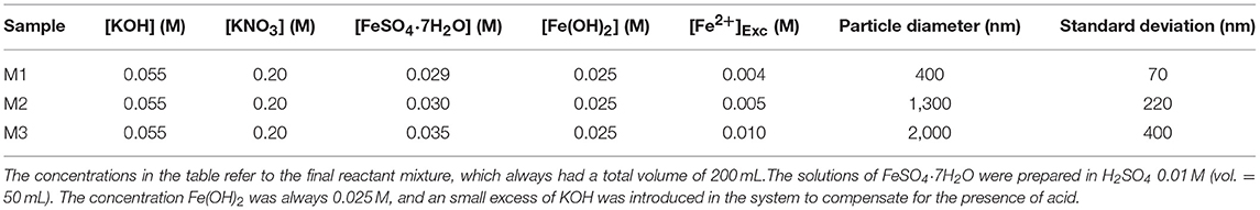
Table 1. Information regarding the synthesis process and the size of the magnetite particles of the three samples.
Scanning electron microscopy (SEM) was the main tool used for determining particle size. To prepare the samples for microscopy analysis, the magnetic powders were redispersed in the ethanol in which they were stored, and a small aliquot was dried and then coated with a thin (ca. 10 nm) layer of carbon.
MR Fluid Preparation
The MR fluids were prepared by dispersing the proper amount of dry magnetite powder in a mixture of glycerol and water with a mass concentration of 88% glycerol. Glycerol was chosen as a liquid carrier due to its properties as polar, biocompatible, and highly viscous liquid, which readily dissolves in water. Regarding all these properties, our expectation was to achieve an extension of the hydrodynamic regime to lower sliding speeds, due to the high viscosity. Moreover, in a recent work by Shahrivar et al. (2017), it was demonstrated that the viscosity of the carrier fluid plays an important role when it comes to particle aggregation. Being the glycerol a high viscosity carrier, the magnetite particles should be better dispersed, minimizing particle aggregation during the experiments. The particle concentration for all the MR fluids was chosen properly and set to be 1 vol%. A density of 5.17 g cm−3 was assumed to calculate the mass of the solid phase. Dispersion of the particles was achieved by means of mechanical stirring followed by sonication.
Friction Measurement Method
To perform the friction measurements we used a contact geometry of non-conforming ball-on-three-plates, based on a modified form of the MCR302 rheometer (Anton Paar). In this particular experimental set-up, a PMMA ball of radius R (R = 0.25 inch = 6.35 mm) is mounted into a stem and then loaded at a determined normal force FN against three plates, which are mounted over a special movable holder with their surfaces arranged in tetrahedral geometry relative to the ball's rotation axis, ensuring equal applied load distribution on the three frictional pairs. Afterwards, the ball starts to rotate at a given sliding speed V while the plates remain stationary, hence producing three stationary sliding point contacts. In this device (see Figure 1), the sliding speed V is related to the angular velocity (ω, rad/s) through . The total normal load FL applied acting on the plates, due to this configuration (plates at 45°), is related to the normal force FN as follows (Shahrivar and de Vicente, 2014):
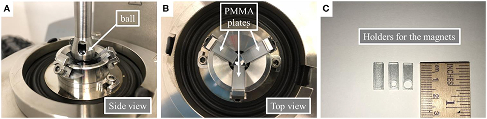
Figure 1. Experimental set-up of the ball on-three-plates contact for tribology tests in the absence or the presence of magnetic fields: (A,B) Schematics of the ball-on-three-plates contacts without magnetic fields applied; (C) Detail of the 3D printed holder employed to superimpose non-homogeneous magnetic fields.
In this study, the applied normal force FN is equal to 0.5 N, in order to minimize the ball-plate contact as much as possible. Furthermore, the torque sensed by the ball, T, is related to the total frictional force, FF, in this fashion:
Eventually, the friction coefficient can be obtained from:
where FF is the frictional force and T is the torque sensed by the ball.
All the tests were carried out at a temperature of 25°C and at a constant slide-to-roll ratio of SRR = 2 (i.e., pure-sliding conditions). All PMMA plates used had a thickness of 2 mm and they were placed over 1 mm thick spacers. In order to apply magnetic fields, a special set of spacers with cylindrical holes has been fabricated, which were used to hold cylindrical neodymium–iron–boron (NdFeB) permanent magnets (one for each spacer) in contact with the polymer plates (PMMA) at the required position. Those cylindrical NdFeB magnets (with 1 mm height) have 3 and 5 mm diameters and they generate a maximum magnetic field on their surface of 250 and 170 mT, respectively. However, due to the thickness of the PMMA plates (2 mm), at the contact point the measured magnetic fields are reduced to 22 and 14 mT for the 3 and 5 mm magnets, respectively. The materials used in the experimental set-up were non-magnetic and therefore no conduction of the magnetic flux density is expected.
Confocal Microscopy
Topography measurements of the PMMA plates were performed using a confocal microscope Sensorfar PLμ 2300 Optical Imaging Profiler. This equipment enabled us to measure the 3D topography of all PMMA plates used in the tribology experiments. Therefore, we performed measurements of wear scar diameter, surface roughness, and mean wear volume using 10 × magnification, which covers an area of 1.39 × 1.02 mm2.
Results
Magnetite Particles
In order to obtain the size histogram of the magnetic particles, a set of samples were prepared to be analyzed using Scanning Electronic Microscopy (SEM). Figure 2 shows representative SEM micrographs, obtained under the same magnification, of the three samples synthesized at different excess of Fe2+, together with the size distribution of each sample.
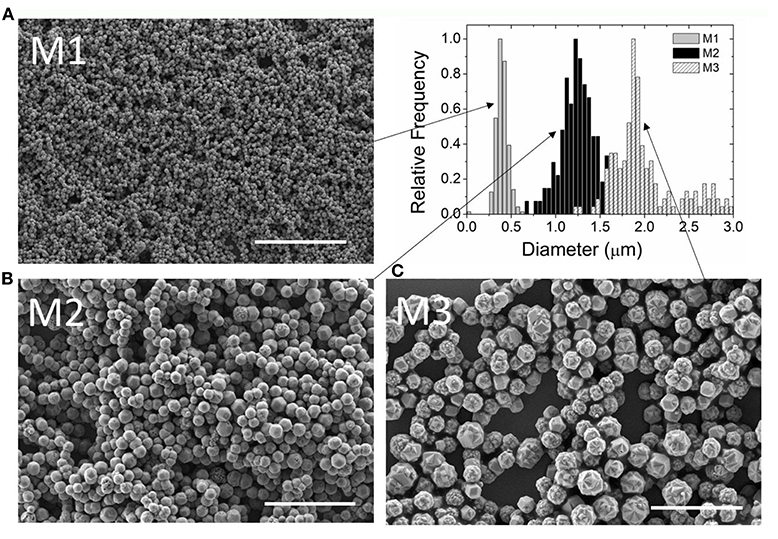
Figure 2. SEM micrographs of magnetite particles obtained for different [Fe2+]Exc concentrations: (A) M1; 0.004 M; (B) M2; 0.005 M; and (C) M3; 0.01 M. Scale bar is 10 μm.
Visual inspection of the micrographs suggests that, for each sample, the particle size is relatively uniform. The actual particle size distributions were calculated using ImageJ software (Rueden et al., 2017). The diameter of, at least, 225 particles was measured for each sample. The results of these measurements for the different [Fe2+]Exc are summarized in Table 1.
As can be observed, the particle size varies in a range from 400 to 2,000 nm and the standard deviations are close to 18% of the average diameters, for samples M1 and M2, and goes up to 20% for sample M3. Moreover, for the larger particles, the kinetics of particle growth (Vereda et al., 2013) results in a rough surface morphology, as opposed to the smoother surfaces observed for the smaller particles.
We knew, from previous studies (Vereda et al., 2013), that all these particles exhibit very similar magnetic properties. Concretely, they have a saturation magnetization close to the bulk value frequently reported for magnetite (92 A·m2·kg−1) at room temperature, and they exhibit soft hysteresis loops, with low values of both the remanence and the coercivity. The latter agrees with the fact that these particles are big enough to contain multiple magnetic domains, so that magnetization reversal occurs by motion of domain walls.
Friction Experiments and Stribeck Curve
The measured friction coefficients are displayed in Figure 3. The resultant plotted curves are composed from an average of three measurements using the same conditions (ramping down from 2,800 rpm to 0, or 1.3 m/s to 0). Firstly, we analyze the effect of the different particle addition to the glycerol/water mixture (88%). Comparing the friction coefficients for each of the suspensions, we can note that the friction coefficient changes drastically from pure glycerol/water mixture to MR fluids (see Figure 3A). The classical Stribeck curve is observed for the carrier (without particles); boundary regime at small speeds, mixed regime at intermediate speeds and full film isoviscous-elastohydrodynamic lubrication regime for large speeds (Stribeck, 1902; Bombard and de Vicente, 2012; Wäsche and Woydt, 2014). In MR fluids, particles with larger diameters (M2 and M3) present larger friction coefficients, although the particle concentration is kept constant through the experiments (1 vol%). Moreover, the friction coefficient is nearly constant through the whole sliding speed range for those MR fluids (M2 and M3).
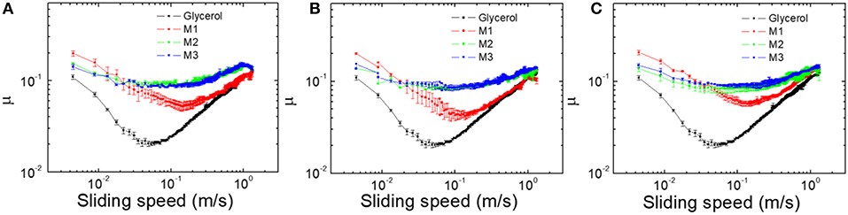
Figure 3. Variation of the friction coefficient with the sliding speed for: (A) 0 mT, (B) 14 mT; and (C) 22 mT.
The presence of a non-homogeneous magnetic field (see Figures 3B,C) produces a slight decrease on the friction coefficients, although the change is not dramatic. Figure 4 displays the variation of the friction coefficient as a function of the particle size in a range of sliding speeds (from 0.22 to 0.99 m/s). The effect of the applied magnetic field is also plotted in this figure (see Figures 4B,C). As one can observe, the presence of the magnetic field tends to slightly reduce the friction coefficients. Compared to the values obtained without any magnetic field applied, the decreasing of the friction coefficient is around 11% for both 14 and 22 mT, corresponding to 5 and 3 mm magnets diameter, respectively. This reduction can be explained as the magnetite particles have the tendency to be concentrated around the area where the magnetic field is acting and, then, this leads to the formation a thin film of magnetic particles around the contact area, preventing the ball-plate contact as much as possible. Such a reduction in friction upon the application of a magnetic field was also observed by Shahrivar et al. for the lubrication with a comercial iron-based MR fluid (Sharivar et al., 2014).
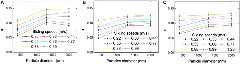
Figure 4. Variation of friction coefficient as a function of particle diameter for: (A) 0 mT, (B) 14 mT; and (C) 22 mT.
Lubrication Regime and Film Thickness Calculations
In order to determine the lubrication regime for these MR fluids, we estimated the values for hard contacts in glycerol/water mixtures (88% glycerol). In addition to their inherently high viscosities at normal conditions of ambient pressure and temperature, the pressure-viscosity coefficients (α) of aqueous glycerol mixtures can be used also to improve the load-bearing capacity of hard contacts, therefore opening the possibility to manipulate, and modify the working lubrication regime. Former theoretical models have explicitly demonstrated that, basically, the two main parameters responsible for determining the nature of the fluid film formed between the contacting surfaces are both the elasticity of the contact material and the viscosity of the lubricant (Hamrock and Dowson, 1978). In that regard, the relative magnitudes of these quantities are key to determine in which type of fluid-film lubrication regime we are working. Mainly, we can divide these regimes into four specific types: iso-viscous rigid (IR), piezo-viscous rigid (VR), iso-viscous elastic (IE), and piezo-viscous elastic (VE). All the equations used in the calculation of the dimensionless viscosity and elasticity parameters, for the contacts, are given by Hamrock and Dowson (1978) and Esfahanian and Hamrock (1991).
where G, W, and U are the dimensionless material parameter, dimensionless load parameter, and dimensionless speed parameter, respectively. These dimensionless parameters are normally used in elastohydrodynamical lubrication and are defined as follow:
where α is the pressure-viscosity coefficient of the lubricant, E′ is the effective elastic modulus, Q is the applied load, η0 is the viscosity of the lubricant in the contact, u is the entrainment speed of the contact, which in our case is the sliding speed divided by two, and Rx is the effective radius of the contact in the sliding direction. The pressure-viscosity coefficients for glycerol-water mixtures have been taken from the literature (Totten, 2000; Shahrivar et al., 2017) and the resulting value for the intermediate aqueous glycerol mixture used in this work was obtained by interpolation. For 88% glycerol-water, the dynamic shear viscosity is estimated to be η = 0.0404 Pa·s. In our experimental set-up, we can consider that the ellipticity parameter (k) is equal to one for the PMMA ball in contact with the PMMA plates, since the contact area is considered to be circular (E′= 5 GPa, Rx = 6.35 10−3 m). Operating conditions of the experiments are then used as input parameters to calculate the non-dimensional elastic (gE) and viscosity (gV) parameters according to Equations 4, 5. The calculated values are plotted in Figure 5. As observed, the contact operates in the isoviscous-elastic regime.
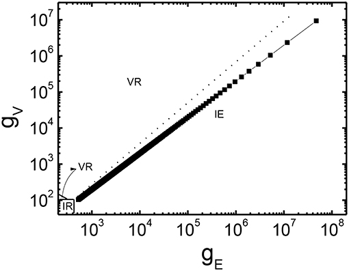
Figure 5. Dimensionless viscosity as a function of the dimensionless elasticity.
Therefore, the estimated lubrication film thickness is calculated from the dimensionless parameters which correspond to those of the isoviscous-elastic regime. For spheres onto flat plates, we can assume that the film thickness in the isoviscous-elastic regime is (de Vicente et al., 2005; Shahrivar and de Vicente, 2014):
where hc is the central film thickness and hm is the minimum film thickness. Figure 6 exhibits the variation of the formed thin film thickness with the entrainment velocity. In our experiments, the maximum values estimated for such thin film thickness is hc = 0.636 and hm = 0.383 μm for an entrainment speed of 0.66 m/s (2,800 rpm), which is the highest possible rotational speed in our measurement system. This means that only the smallest particles could be entrained in the contact during a test.
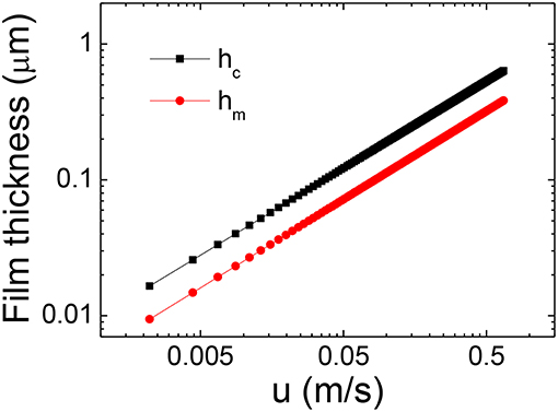
Figure 6. Thin film thickness as a function of entrainment speed (u = V/2).
In physical tribological contacts, we have to take into account that the contact surfaces have a non-negligible roughness, which can lead to asperities and hard contact friction in comparison to the lubricating film thickness formed at the interface. The so-called λ ratio is a direct comparison between the estimated film thickness and the surface roughness. The λ ratio is given by the following expression (Stachowiak and Batchelor, 1993; Nalam et al., 2010).
where rball is the rms surface roughness of the PMMA ball, rplate is the rms surface roughness of the plate and hm is the minimum film thickness. The λ ratio estimates the lubrication regime for rough surfaces; the λ values indicate a high probability for asperity contact at low speeds (λ < 1) and lubrication regime for high speeds (λ> 1). In this work, the rms roughness values for PMMA ball and PMMA disk used are 126 and 34 nm, respectively (obtained from confocal microscopy images). In Figure 7 we plot the λ values against the entrainment speed for all of the experiments. The curve shows that all the contacts during tribological measurements were in the boundary-lubrication regime. A good correspondence is observed with the minimum in the friction coefficient also shown in Figure 7. The transition from the mixed to the hydrodynamic regime occurs for value of λ in the vicinity of 0.4, which is much lower than the values reported by other authors (Hamrock and Dowson, 1978; de Vicente et al., 2005) maybe due to the different elastic modulus of the compliant surfaces.
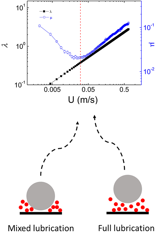
Figure 7. Lambda ratio (λ–black symbols) and glycerol friction coefficient (μ–blue symbols) as a function of the entrainment speed. Dashed line indicates the transition from mixed state to full lubrication regime.
Wear Scar and Roughness Analysis: Fixed Sliding Speed
To investigate the role of the particle size, we performed a series of measurements fixing the normal force at FN = 0.5N and sliding speed at 2,500 rpm (1.18 m/s) to promote the formation of a thin film in the contact. Tests are then conducted for different time intervals from 2 up to 10 min. In particular, for that sliding speed, a thin film thickness around 0.5 microns is expected, following the assumptions and the data plotted in Figure 6 (hc thin film value). In Figures 8, 9, we can observe the wear scars produced by the magnetite particles after acting by 2 and 10 min, respectively. From these topography images, we were able to determine and measure the maximum depth removal, volume eroded, and the rms surface roughness of the wear scars. The maximum material removal depth for the different samples can be visualized in Figure 10. The MR fluids prepared with particles of larger diameters (M3) display a higher abrasion, having a maximum removal depth of 14.7 microns. As seen on this figure, the action of the applied magnetic field is minimum in the field range investigated (14 or 22 mT). In conjunction of the maximum removal depth analysis, we have compared the evolution of the wear scar diameter and rms surface roughness after the abrasion performed by the magnetite particles. Figure 11 shows a comparison between the measurements of average wear scar diameter and rms surface roughness with and without applied magnetic field. As we can appreciate, the effect of the applied magnetic field is more relevant for the smaller particles (M1), in which case the size of wear scar diameter and rms roughness is reduced when compared to the values of those without the magnetic field. The minimum rms roughness are achieved when the 14 mT magnetic field is applied (355 ± 18 nm). The 5 mm magnet, at the contact point, produces a more homogeneous magnetic field, in comparison to the 3 mm magnet, leading to a larger area of particle concentration. In that sense, we understand that the fact that triggers the decrease of the wear scar dimensions, in the case of MR fluid lubrication in the presence of magnetic fields, is the magnetic field gradient, which promotes particle agglomeration in a given region of the space around the magnets. This produces a confinement of the abrasion region to a small zone, which is in agreement with previous reports (Song et al., 2011; Hu et al., 2012).
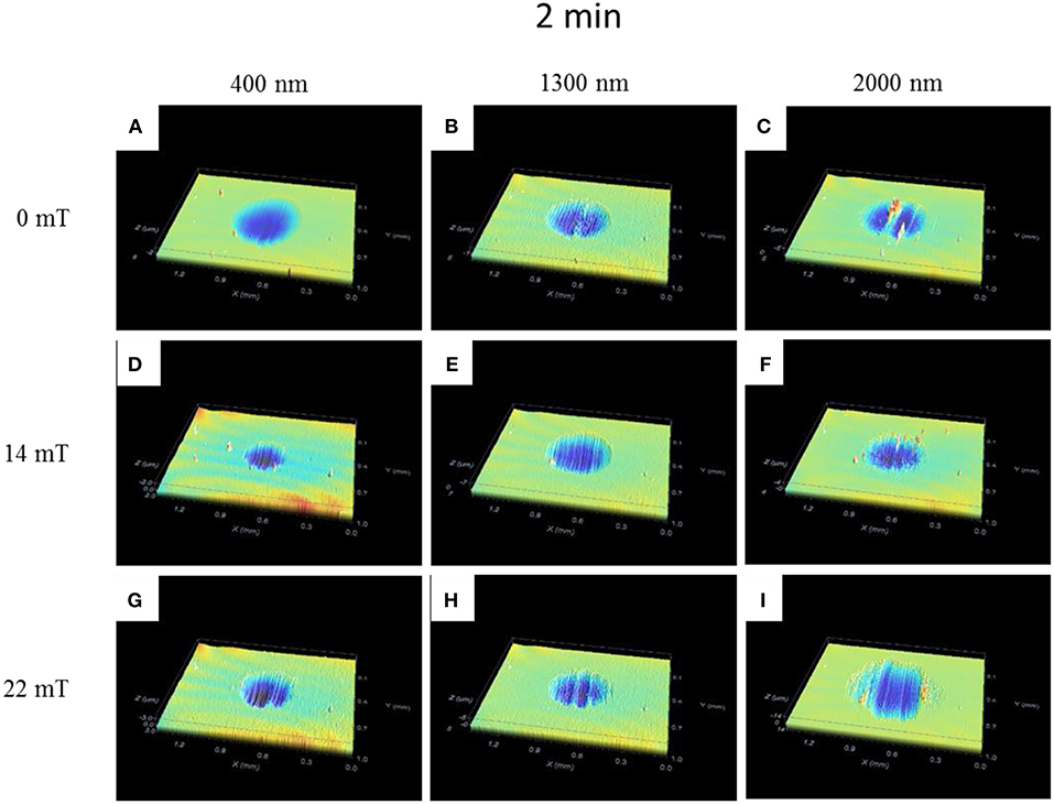
Figure 8. Topography images obtained from PMMA plates after 2 min at 1.18 m/s: (A,D,G) M1; (B,E,H) M2 and; (C,F,I) M3 (window sizes of 1.39 × 1.02 mm).
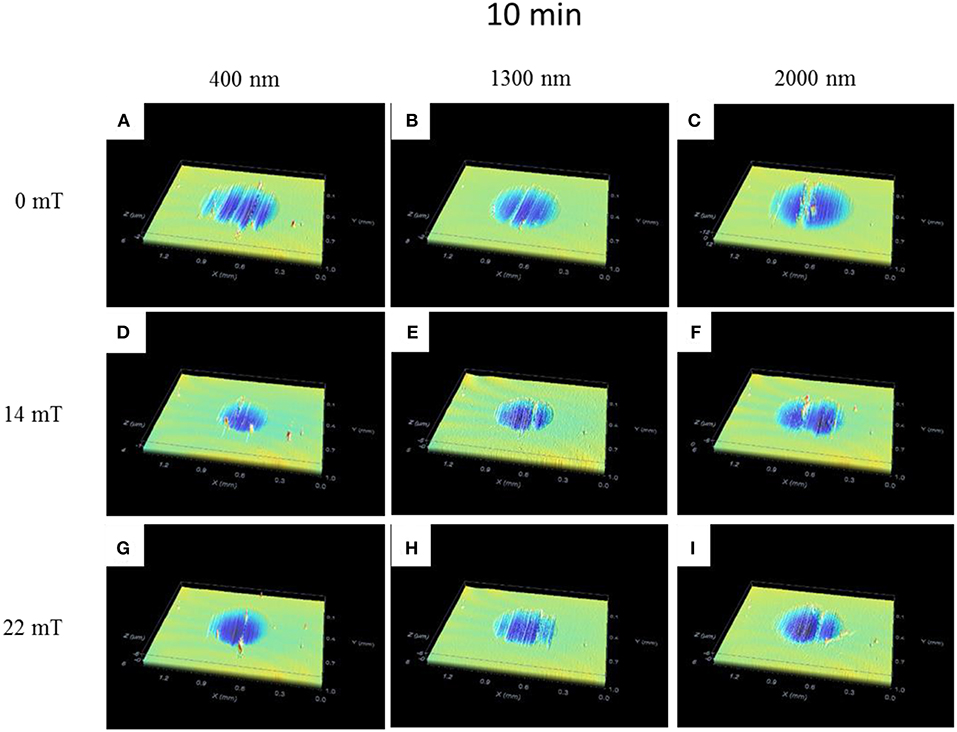
Figure 9. Topography images obtained from PMMA plates after 10 min at 1.18 m/s: (A,D,G) M1; (B,E,H) M2 and; (C,F,I) M3 (window sizes of 1.39 × 1.02 mm).
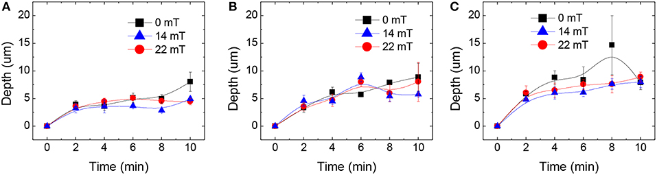
Figure 10. Maximum removal depth as a function of time for (A) M1, (B) M2, and (C) M3 MR fluids. Lines are shown as a guide to the eye.
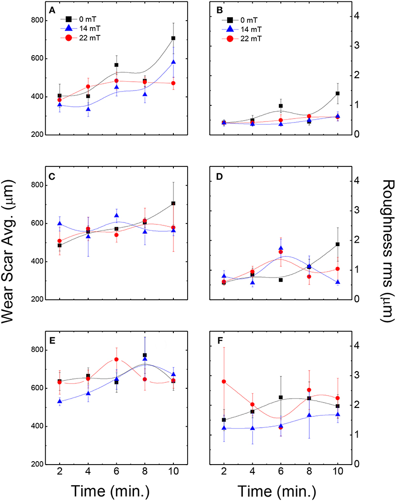
Figure 11. Average wear scar diameter (A M1, C M2, E M3) and rms surface roughness (B M1, D M2, F M3) for different magnetite particles. Lines are shown as a guide to the eye.
Furthermore, the negligible magnetic field effect for the larger particles can be associated to the resultant film thickness formed for glycerol 88% that, in our predictions, is lower than those particle sizes.
Figure 12 summarizes the mean wear volume produced by the different magnetite particles over the PMMA plates. It is worth noting the effect of the applied magnetic field, which displays the tendency to increase the wear volume for short periods (up to 4 min) and, conversely, to decrease the wear volume after more than 8 min. At this stage, the non-homogeneous magnetic field generates a film of magnetite particles that prevent further abrasions at surface level. This protection against abrasion over time makes these MR fluids to act like antiwear and antifriction catalysts, which was previously described by Duradji et al. (2016).
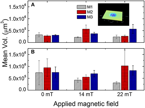
Figure 12. Mean volume of the wear scars after (A) 2 min and (B) 10 min.
Conclusions
We studied the effect of particle size on the tribological behavior of model MR fluids. Magnetite particles with a broad range of sizes (from 400 to 2,000 nm) were synthesized with high reproducibility by chemical methods. The tribological behavior of MR-fluid-lubricated PMMA–PMMA point contacts was compared in a custom-built experimental set-up, both in the absence and in presence of magnetic fields. Relevant differences between the MR fluids were observed after measuring their friction coefficients. In all cases, an elastohydrodynamic regime was achieved at relatively slow sliding speeds (from 0.1 m/s and beyond) and, therefore, a lubricating thin-film whose thickness we could estimate was formed. The effect of a magnetic field in the frictional properties of the lubricated contacts was more noticeable for the larger magnetite particles (M2 and M3). Those MR fluids experienced a decrease in the friction coefficient. From lamba ratio calculations we can assure that, for entrainment speeds over 0.05 m/s, we had a full lubrication regime, with very low probability of asperity contact. The application of a magnetic field during the fixed sliding speed tests shows a slight friction reduction for the MR fluids, as a result of the concentration of the iron particles within a confined region, determined by the area of each magnet used and their generated magnetic field. With the increase of the sliding distance (i.e., time × sliding speed), the effect of magnetic field in the frictional properties is more noticeable. However, after a certain time/sliding distance, the maximum removal depth does not increase, with the MR fluids acting like a protective layer preventing further abrasions. The wear scars and rms surface roughness produced by the MR fluids abrasion, over time, shows that the smaller particles (M1) have the tendency to generate smoother wear scars than the other studied MR fluids.
Author Contributions
WR performed the experiments and data analysis. FV synthetized the magnetite particles. JdV designed this research work. WR, FV, and JdV wrote the manuscript.
Funding
This work was supported by PCIN-2015-051 and MINECO MAT 2016-78778-R projects (Spain), and European Regional Development Fund (ERDF).
Conflict of Interest Statement
The authors declare that the research was conducted in the absence of any commercial or financial relationships that could be construed as a potential conflict of interest.
References
Akkus, A., and Gorgun, E. (2015). The investigation of mechanical behaviors of poly methyl methacrylate (PMMA) with the addition of bone ash, hydroxyapatite and keratin. Adv. Mater. 4, 16–19. doi: 10.11648/j.am.20150401.14
Bombard, A. J. F., and de Vicente, J. (2012). Thin-film rheology and tribology of magnetorheological fluids in isoviscous-EHL contacts. Tribol. Lett. 47, 149–162. doi: 10.1007/s11249-012-9971-2
Byun, J. Y., Pratama, P., Kim, J. H., Park, I. S., Choi, S. M., Kwon, S. H., et al. (2017). The friction and wear characteristic comparison of PMMA and MC nylon as spreading device pad material in copper coil forming. Key Eng. Mater. 723, 220–223. doi: 10.4028/www.scientific.net/KEM.723.220
de Vicente, J., Klingenberg, D. J., and Hidalgo-Álvarez, R. (2011). Magnetorheological fluids: a review. Soft Matter. 7, 3701–3710. doi: 10.1039/c0sm01221a
de Vicente, J., Stokes, J. R., and Spikes, H. A. (2005). The frictional properties of Newtonian fluids in rolling–sliding soft-EHL contact. Tribol. Lett. 20, 273–286. doi: 10.1007/s11249-005-9067-3
Duradji, V. N., Kaputkina, D. E., and Duradji, A. (2016). Tribological studies of antiwear antifriction composition and its application. Tribology in Industry 38, 496–507.
Esfahanian, M., and Hamrock, B. J. (1991). Fluid-film lubrication regimes revisited. Tribol. Trans. 34, 628–632. doi: 10.1080/10402009108982081
Gu, D., Zhang, L., Chen, S., Song, K., and Liu, S. (2018). Significant reduction of the friction and wear of PMMA based composite by filling with PTFE. Polymers 10:996. doi: 10.3390/polym10090966
Hamrock, B. J., and Dowson, D. (1978). “Minimum film thickness in elliptical contacts for different regimes of fluid-film lubrication,” in Proceedings-Society of Photo-Optical Instrumentation Engineers, NASA-TP-1342 (Cleveland, OH).
Hu, Z. D., Yan, H., Qiu, H. Z., Zhang, P., and Liu, Q. (2012). Friction and wear of magnetorheological fluid under magnetic field. Wear 278–279, 48–52. doi: 10.1016/j.wear.2012.01.006
Itoh, H., and Sugimoto, T. (2003). Systematic control of size, shape, structure, and magnetic properties of uniform magnetite and maghemite particles. J. Coll. Int. Sci. 265 283–295. doi: 10.1016/S0021-9797(03)00511-3
Kaewsaneha, C., Tangboriboonrat, P., Polpanich, D., Eissa, M., and Elaissari, A. (2013). Janus colloidal particles: preparation, properties, and biomedical applications. ACS Appl. Mater. Interfaces 5, 1857–1869. doi: 10.1021/am302528g
Lei, W., Liu, Y., Si, X., Xu, J., Du, W., Yang, J., et al. (2017). Synthesis and magnetic properties of octahedral Fe3O4 via a one-pot hydrothermal route. Phys. Lett. A 38, 314–318. doi: 10.1016/j.physleta.2016.09.018
Nalam, P. C., Clasohm, J. N., Mashaghi, A., and Spencer, N. D. (2010). Macrotribological studies of Poly(L-lysine)-graft-Poly(ethylene glycol) in aqueous glycerol mixtures. Tribol. Lett. 37, 541–552. doi: 10.1007/s11249-009-9549-9
Nuño, N., Amabili, M., Groppetti, R., and Rossi, A. (2002). Static coefficient of friction between Ti-6Al-4V and PMMA for cemented hip and knee implants. J. Biomed. Mater. Res. 59, 191–200. doi: 10.1002/jbm.1233
Odenbach, S., and Thurm, S. (2002). Magnetoviscous Effects in Ferrofluids. Berlin; Heidelberg: Springer-Verlag.
Park, B. J., Fang, F. F., and Choi, H. J. (2010). Magnetorheology: materials and application. Soft Matter. 6, 5246–5253. doi: 10.1039/c0sm00014k
Rueden, C. T., Schindelin, J., Hiner, M. C., De Zonia, B. E., Walter, A. E., Arena, E. T., et al. (2017). ImageJ2: ImageJ for the next generation of scientific image data. BMC Bioinformatics 18:529. doi: 10.1186/s12859-017-1934-z
Sahiner, N., and Yasar, A. O. (2016). A new application for colloidal silica particles: natural, environmentally friendly, low-cost, and reusable catalyst material for H2 production from NaBH4 methanolysis. Ind. Eng. Chem. Res. 55, 11245–11252. doi: 10.1021/acs.iecr.6b03089
Shahrivar, K., Carreón-González, E., and de Vicente, J. (2017). On the importance of carrier fluid viscosity and particle-wall interactions in magnetic guided assembly of quasi-2D systems. Microfluid Nanofluid 21:120. doi: 10.1007/s10404-017-1955-y
Shahrivar, K., and de Vicente, J. (2014). Ferrofluid lubrication of compliant polymeric contacts: effect of non-homogeneous magnetic fields. Tribol. Lett. 56, 281–292. doi: 10.1007/s11249-014-0408-y
Sharivar, K., Ortiz, A. L., and de Vicente, J. (2014). A comparative study of the tribological performance of ferrofluids and magnetorheological fluids within Steel-plate point contacts. Tribol. Int. 78, 125–133. doi: 10.1016/j.triboint.2014.05.008
Song, W.-L., Choi, S.-B., Choi, J.-Y., and Lee, C.-H. (2011). Wear and friction characteristics of magnetorheological fluid under magnetic field activation. Tribol. Trans. 54, 616–624. doi: 10.1080/10402004.2011.584365
Stribeck, R. (1902). Die wesentlichen Eigenschaften der Gleit- und Rollenlager. Zeitschrift des Vereins Deutscher Ingenieure 36, 1463–1470.
Sugimoto, T., and Matijevic, E. (1980). Formation of uniform spherical magnetite particles by crystallization from ferrous hydroxide gels. J. Coll. Int. Sci. 74, 227–283. doi: 10.1016/0021-9797(80)90187-3
Thomson, L. A., Law, F. C., James, K. H., Matthew, C. A., and Rushton, N. (1992). Biocompatibility of particulate polymethylmethacrylate bone cements: a comparative study in vitro and in vivo. Biomaterials 13, 811–818. doi: 10.1016/0142-9612(92)90173-L
Vereda, F., de Vicente, J., and Hidalgo-Álvarez, R. (2007). Influence of a magnetic field on the formation of magnetite particles via two precipitation methods. Langmuir 23, 3581–3589. doi: 10.1021/la0633583
Vereda, F., Morales, M. P., Rodríguez-González, B., de Vicente, J., and Hidalgo, R. (2013). Control of surface morphology and internal structure in magnetite microparticles: from smooth single crystals to rough polycrystals. Cryst. Eng. Commun. 15, 5236–5244. doi: 10.1039/c3ce40424b
Wäsche, R., and Woydt, M. (2014). “Stribeck curve,” in Encyclopedia of Lubricants and Lubrication, eds T. Mang (Berlin; Heidelberg: Springer), 1998–2005 doi: 10.1007/978-3-642-22647-2_274
Xiang, L., Gao, C., Wang, Y., Pan, Z., and Hu, D. (2014). Tribological and tribochemical properties of magnetite nanoflakes as additives in oil lubricants. Particuology 17, 136–144. doi: 10.1016/j.partic.2013.09.004
Keywords: PMMA, boundary lubrication, particle size, abrasion, sliding friction
Citation: Rosa WO, Vereda F and de Vicente J (2019) Tribological Behavior of Glycerol/Water-Based Magnetorheological Fluids in PMMA Point Contacts. Front. Mater. 6:32. doi: 10.3389/fmats.2019.00032
Received: 03 December 2018; Accepted: 14 February 2019;
Published: 08 March 2019.
Edited by:
Seung-Bok Choi, Inha University, South KoreaReviewed by:
Wanli Song, Northeastern University, ChinaYu Tian, Tsinghua University, China
Chul-Hee Lee, Inha University, South Korea
Copyright © 2019 Rosa, Vereda and de Vicente. This is an open-access article distributed under the terms of the Creative Commons Attribution License (CC BY). The use, distribution or reproduction in other forums is permitted, provided the original author(s) and the copyright owner(s) are credited and that the original publication in this journal is cited, in accordance with accepted academic practice. No use, distribution or reproduction is permitted which does not comply with these terms.
*Correspondence: Juan de Vicente, anZpY2VudGVAdWdyLmVz