 Ying Zhou*
 Peng Chen
- State Key Laboratory of Disaster Reduction in Civil Engineering, Tongji University, Shanghai, China
This paper proposes a new viscoelastic (VE) material damping device with hybrid non-linear properties. Compared with traditional linear material dampers, the new non-linear VE material damping device is characterized by its better energy dissipation and deformation capability. The series performance tests of the VE device are conducted, based on which the sources and variation law of material non-linearities are analyzed. Five aspects of material non-linearities are summarized, including the shape change of hysteresis loop caused by phase difference, the initial stiffness caused by large loading rate, the softening effect caused by high temperature and fatigue, and the softening and stiffening effect under large strain deformation. A mechanic model for this device is proposed which considers multiple non-linear effects of the material. For the verifications of the proposed mechanic model, a shaking table test on a steel frame equipped with the new VE devices is designed and performed. Based on the proposed mathematic mechanic model, the numerical mechanic model is implemented in the OpenSees software. The accuracy of the mechanic model is firstly verified by comparing the performance tests data with the simulation results. Then the numerical model is also used to calculate the time history response of the shake table tested steel frame under earthquake loading. It is concluded that the mechanic model can well-depict several non-linear material behaviors of the new VE device, and the corresponding numerical model created in the open source calculation platform is reliable to be used to calculate non-linear time history response of a structure equipped with the new VE material damping devices.
Introduction
The viscoelastic (VE) damper is one of the most popular passive energy dissipation devices for building structures under earthquake and wind disasters. In 1969, the VE damper was firstly used in the New York World Trade Center for wind-induced vibration control (Mahmoodi et al., 1987). After that, the VE dampers began to be used in the seismic design for buildings. In 1993, the VE dampers were used in seismic design for a 13-story steel frame retrofit project (Crosby et al., 1994). Since then, increasing research attentions have been paid on this topic, the VE damping devices have been investigated for vibration control of different types of structures including concrete building, steel building, prefab building, wood structure, bridge, base isolated structures, etc. (Samali and Kwok, 1995; Soong and Spencer, 2002; Xu et al., 2003a, 2011, 2013; Molinera et al., 2012; Wu et al., 2015; Gong et al., 2017).
With the fast development of viscoelastic damping material, VE damping devices with better energy dissipation and deformation capacity have been proposed. The better performance devices are always characterized by complex non-linear properties. By the stress-strain relation, the VE dampers can be categorized into four types: the linear, softening, hardening, and hybrid non-linear type (Gong and Zhou, 2017). For the linear type device, the mechanic properties are strain independent if the temperature influence is not included (Lai et al., 1996). The stiffness of the softening and hardening type devices will decrease and increase, respectively, with larger strain. In addition to these, this paper reveals a new type of VE damping device containing both softening and hardening effects which are defined as hybrid non-linearity.
Many previous studies have been investigating the working performance of the VE damping devices. Chang et al. (1992, 1995) and Lai et al. (1995) conducted extensive performance tests and a small scaled shake table test on a five-story steel frame with the linear VE dampers. The results prove that the VE damping devices can have a significant earthquake control effect and the mechanic behavior of the device can be well-represented using effective linear stiffness and effective damping. Xu et al. (2003b, 2004) and Xu (2009) experimentally investigated the effect of the VE dampers on a reinforced concrete building. It is concluded that the earthquake mitigation effect is significant, especially for the floor acceleration and displacement reduction. Another conclusion is that the control effect for higher frequency input is superior to lower frequency.
For non-linear VE damping devices, the investigations are fundamentally based on tests and also focus on the mechanic models which can depict the complex mechanic behavior of non-linear VE dampers. Aiken et al. (1993) studied on softening VE dampers, and the frequency dependent property of the VE dampers is summarized based on the tests. Yokota et al. (1992) conducted a comparison study between models with and without non-linear VE damping devices. It is concluded that the seismic mitigation effect for floor displacement is significant but the effect on floor shear force reduction is limited and the main seismic reduction effect comes from the additional damping. Xu et al. (2016) proposed an equivalent higher-order fractional derivative model which takes into account the temperature effects and frequency-dependent character of the non-linear VE devices with different matrix rubbers. Ghaemmaghami and Kwon (2018) proposed an extended recursive parameter model to simulate the frequency-, strain- and temperature-dependent properties of non-linear VE damper and the simulation results can better depict the experiment behavior compared with traditional Kelvin-Voigt model. The investigations on the hardening type device are limited. (Dall'Asta and Ragni, 2006) conducted performance tests on a type of high damping rubber material, and the material shows a significant stiffen character. Pant et al. (2018) performed a full-scale test of a viscoelastic damper, and the accuracy of four different macroscopic numerical models are discussed. Results reveal that different models are suitable for modeling VE damping devices under different loading conditions.
According to the above literature review, we still lack enough knowledge of the non-linear sources and laws of non-linearities. Many experiment phenomenon cannot have convincible explanations, and few mechanic models can accurately depict the mechanic behavior of VE damping device with multiple non-linear mechanic behaviors or hybrid non-linearities coexisting in VE damping devices.
This paper introduces a VE damping device using new viscoelastic material. The main components of the material are natural rubber, damping agent, and antioxygen. The new damping device is characterized by its hybrid non-linearities which can have a better energy dissipation and deformation capacity, and it is supposed to have a better seismic reduction effect compared with linear type devices. Based on the analysis of the different sources of non-linearities, a new mathematic mechanic model which considers multiple non-linear behaviors is proposed. The results of performance tests are compared with the theoretical curves to validate the model. Then, a shake table test on a steel frame with new VE damping devices is conducted, and a discrete numerical model is created in an open source computing platform to calculate the time history response of the tested model. By comparing the shake table test and numerical simulation results, the remarkable seismic control effect of the new VE damping device is proved, and also the accuracy of the mechanic model is verified.
Performance Tests
Three different types of hybrid non-linear VE dampers are tested, numbered as “VE40 × 40 × 8,” “VE100 × 100 × 5,” and “VE60 × 60 × 10.” The size and configuration of the three different types of specimens are shown in Figure 1. The performance tests were performed at the State Key Laboratory of Disaster Reduction in Civil Engineering of Tongji University. The testing facilities are shown in Figure 2A. The “INSTRON” tension-compression loading device is used to perform harmonic displacement-control loading process. The range of loading frequency is 0.1–6.0 Hz, and the strain deformation is 50–400%. The temperature related performance tests were conducted at General Building Research Corporation of Japan. The testing picture is shown in Figure 2B. The variation of temperature is between −20 and 60°C. The loading scheme is listed in Table 1. A single specimen of different damper sizes are used for each test case.
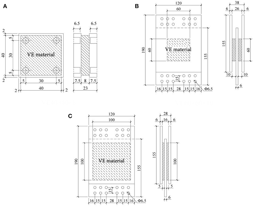
Figure 1. Diagram of the different type of test specimens of (A) type “VE40 × 40 × 8,” (B) type “VE60 × 60 × 10” and (C) type “VE100 × 100 × 5”.
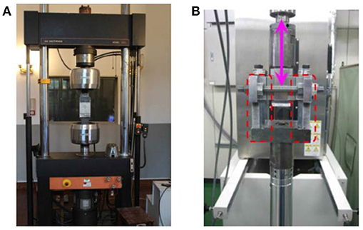
Figure 2. Testing facilities of (A) performance tests and (B) performance tests under different temperatures.
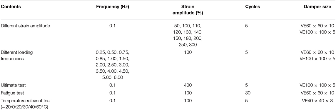
Table 1. The loading scheme of the mechanic performance test.
Figure 3 presents typical hysteresis curves from the performance tests. Based on the hysteresis results, significant characters are concluded as (a) The stiffness and damping of the VE damper decrease with the increase of deformation, but the stiffness begins to increase under larger strain (≥200%); (b) The device presents a large initial stiffness for the loading process of the first cycle; (c) The performance of the damper significantly deteriorate with more loading cycles. After the hysteresis loading of 30 cycles, the damper remains intact and effective; (d) The mechanic behavior of the damper is nearly independent of the loading frequency; (e) The maximum stress of the damper is dependent on the environment temperature, based on the fitting of test results, the relation expression is given as
τ0 is the maximum stress in damper, θ is the temperature (°C). The variations of the damper behavior under different temperatures are shown in Table 2.
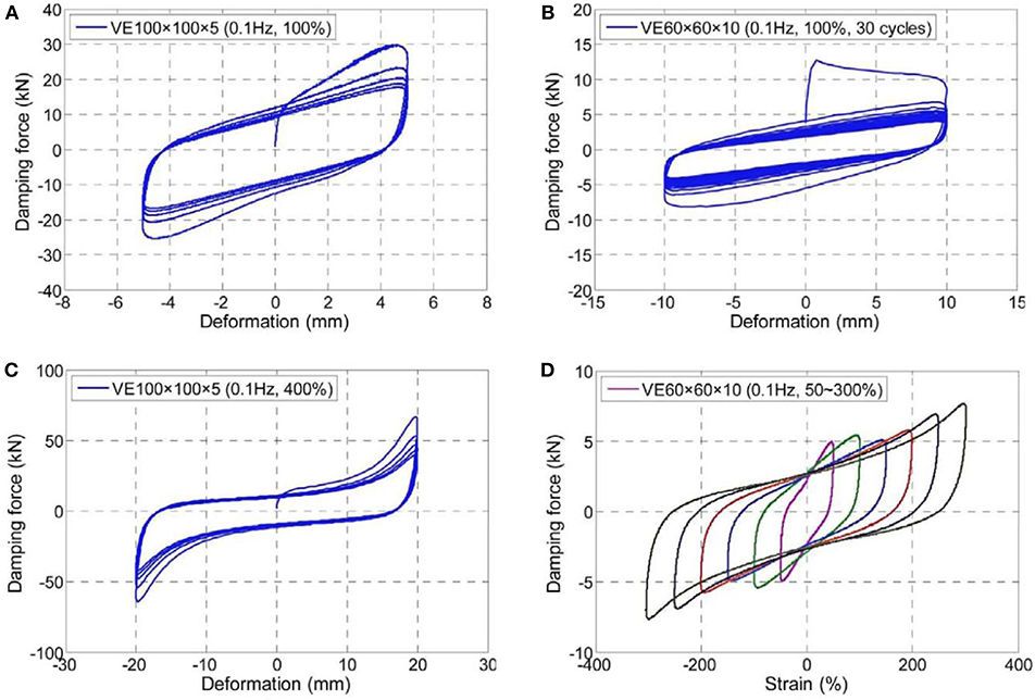
Figure 3. Performance test results of (A) typical hysteresis curve, (B) fatigue test, (C) ultimate strain test, and (D) different strain amplitude tests.
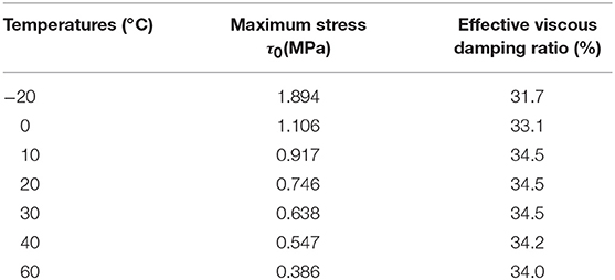
Table 2. Mechanic parameters of the VE damping device under different temperatures.
Sources and Laws of Non-Linearities
The non-linear behaviors of the new VE damping device are obvious and comprehensive which is affected by many factors. Based on the performance tests, five sources of material non-linearity are summarized as phase different, initial stiffness, softening under repeated loading, softening under great strain, and stiffening under considerable strain.
Non-Linearity Caused by the Variation of Phase Difference
For viscoelastic damping devices, the phase difference exists between the strain and the stress which essentially creates the hysteresis loops of the stress-strain relation. Under harmonic displacement control loading, the strain deformation of the VE damper γ(t) = γosinωt, and the stress responseτ(t) = τ0sin(ωt+δ). The stress-strain relation meets the elliptic equation. However, for linear type VE damper, the phase difference δ is a constant value. In contrast, for this new non-linear VE damping device, the phase difference δ(t) varies with time which can cause the shape change of the hysteresis loop.
A more complicated stress response is observed for the non-linear VE damper. The phase difference of the non-linear damper in one period (the duration of one single harmonic loading period) under different strain amplitude is presented in Figure 4. It clearly shows that the phase difference periodically changes with time. The basic reasons are the ultra-harmonic response caused by the stiffness non-linearity. Another interesting observation is that the phase variation amplitude is strain related. The phase change is more drastic under high strain situation (strain amplitude exceeds 200%). The reason is that when the strain goes large, the stiffening effect becomes significant, which would cause more strong ultra-harmonic components in the response.
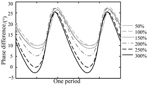
Figure 4. Phase difference comparison in one period.
Initial Stiffness
Figure 3B shows that there is a large initial stiffness in the first cycle due to the sudden increase of the loading frequency (from static to dynamic excitation). If the additional VE devices are not well-designed, the dampers will not generate hysteretic deformation which means the dampers provide only stiffness but no additional damping under this situation. The control effect will be limited if the dampers are not activated. Nevertheless, the problem of the initial stiffness only occurs in the first loading cycle and can be easily overcome by appropriate design. Generally, for the seismic design of buildings, the initial stiffness of VE damper can be ignored if the dampers go through plastic deformation under seismic loading.
Softening Caused by Temperature Rise and Fatigue
The previous study (Lai et al., 1996) concluded that one primary source of non-linearity of VE dampers comes from the temperature effect in the viscoelastic material. Based on this, for the design and analysis of the structures with VE dampers, identical mechanic parameters with temperature correction are used for a large variation range of temperature. The VE material will inevitably subject to temperature rise and fatigue simultaneously under the cyclic loading.
For the new VE damping device, the fatigue tests are conducted using the “VE60 × 60 × 10” specimens. For each testing specimen, 30 loading cycles are conducted. Figure 5 presents the degradation law of different mechanic parameters. Results present that with the increase of the loading cycles, the storage shear modulus, and the loss shear modulus will significantly drop at the first few cycles, but the decrease slows down for the after cycles. Only a slight decrease is observed for the loss factor. For the whole loading process, the effective viscous damping ratio is about 30%. The damping ratio is almost half of the loss factor which is in agreement with linear VE dampers. The definition of the three mechanic parameters are given as,
where the G′, η, and G″ are the storage shear modulus, loss factor and loss shear modulus. F1and F2 are the damping force correlate to the maximum shear deformation u0 and no shear deformation, respectively. h, n, and A are the height, number of layers and area of the damping material.
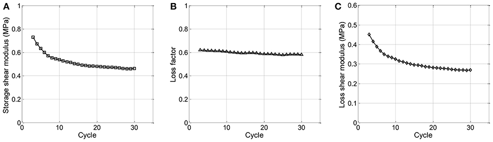
Figure 5. Performance degradation law under cyclic loading on (A) storage shear modulus, (B) loss factor, and (C) loss shear modulus.
Softening and Stiffening Caused by Large Strain
The softening and stiffening effect of the new VE damping device is illustrated in Figure 6. The maximum damping force under different strain deformation is plotted in this backbone curve. It is shown that the stiffness will decrease first with the increase of the strain, then the stiffness begins to increase as the strain goes up to about 200%.
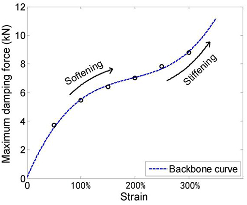
Figure 6. Backbone curve.
The softening phenomenon can be explained as the rubber-like material's Mullins effect (Mullins, 1969). Mullins effect can be illustrated as an instantaneous and irreversible softening that occurs whenever the strain increases beyond its maximum historical value. After that, the equivalent stiffness of VE damper will decrease under all strains. However, there is still no accurate insight physical mechanism that can explain this effect (Diani et al., 2009). If the VE material is bolted tight with its end-plates, the damping device will show an increase in stiffness at large shear deformation. The intrinsic reason for the stiffening effect lies on the strain-induced crystallization of the filled rubber-like material at large shear strain (Kikuchi and Aiken, 1997), (Imbimbo and Kelly, 1998).
The variation of the different mechanic parameters with strain amplitude is presented in Figure 7. Results indicate that the storage shear modulus shows a negative exponential decrease, while the loss shear modulus undergoes linear decrease. The two trends mean that the additional damping decreases faster than the additional stiffness due to the stiffening phenomenon. The loss factor increases initially and then drop down with the increase of strain amplitude. The maximum loss factor corresponds to a strain amplitude range between about 100–150%, which also have a good agreement with the shaking table tests (Zhou et al., 2014).
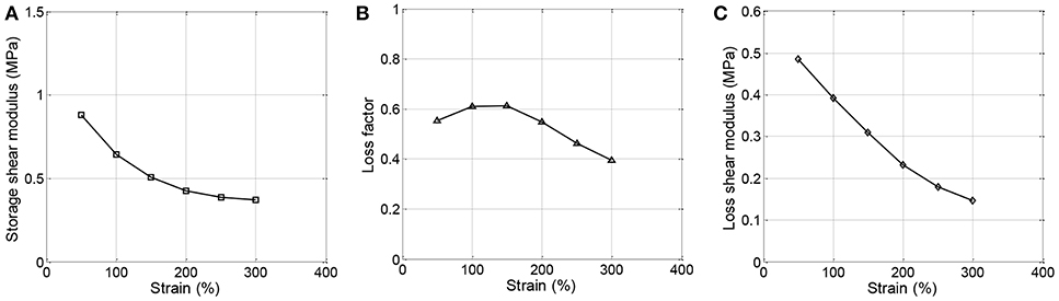
Figure 7. Softening effect on the mechanic parameters of (A) Storage shear modulus, (B) loss factor, and (C) loss shear modulus.
Mechanic Model of the Hybrid Non-linear VE Damper
Many classical mechanic models have proposed to depict the mechanic behavior of VE dampers, including the Maxwell, Kelvin-Voigt, and fractional derivative models (Lewandowski and Chora̧życzewski, 2010). These are the most popular models for VE dampers for the past decades. However, they are not suitable to represent the mechanic properties for this hybrid non-linear type damper. Based on the above performance test investigations, a more accurate model which considers multiple sources of non-linearity is proposed.
Three mechanic elements are set in parallel, including two non-linear stiffness elements and one non-linear viscous dashpot element. The K1(ũ) is the Mullins stiffness element which considers Mullins effect, the stiffness of the element is related to the maximum strain amplitude ũ (in absolute value). The expression of K1(ũ) is given as,
Equation (5) is a quadratic function that can depict softening effect with the increase of strain amplitude. The K2(u) non-linear stiffness element is introduced to include the stiffening effect under large shear strain in the following quadratic form,
The comprehensive expression for the mechanic model of the hybrid non-linear model is given as,
where F, u, and are the force, displacement, and velocity of the damping device; F1, F2, and F3 are the forces provided by Mullins effect element, non-linear stiffness element, and the non-linear dashpot element; K1 and K2 are the stiffness expression of the two corresponding stiffness elements; C and α are the damping coefficient and damping exponent; f is the basic frequency of the structure; ũ is the strain amplitude; a1, a2, a3, b1, b2, C, and α are the mechanic parameters that to be identified based on the performance tests. λ1is the correction factor considering the influence by the ambient temperature; λ2is the correction factor considering the heating-fatigue softening.
The mathematic expression of the proposed mechanical model is concise, and it can depict multiple non-linear behaviors of the hybrid non-linear device, such as the heating-fatigue softening, ambient temperature dependency, frequency-independency, softening, and hardening under large strain. Besides, the parameters are not case dependent, they can be identified and decided by the performance tests described before. The temperature related parameters are given as follow,
where θ is the ambient temperature; ω0is the initial accumulative dissipative energy density; ωtis the accumulative dissipated density at a given time t. Other mechanic related parameters are identified in kN-mm unit as: ; ; a3 = 0.50; ; ; C = 0.8 and α = 0.3.
Verifications of the Mechanic Model of the VE Damping Device
Verifications Via Performance Tests
The proposed model is verified via the performance tests. Figure 8 presents the comparisons between test and modeling curves under different strain amplitude. Results indicate that the hysteresis loops derived by the mechanic model agree well with the testing curves.
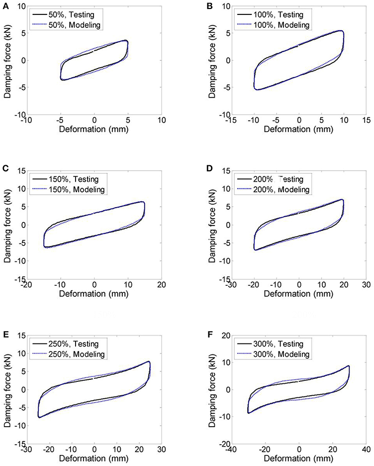
Figure 8. Comparison between the mechanic model and the performance test hysteresis loop (VE60 × 60 × 10) under strain deformation of (A) 50%, (B) 100%, (C) 150%, (D) 200%, (E) 250%, and (F) 300%.
Design of the Shake Table Tests
A three-story steel frame with a height of 4.90 m. In the first and second stories, there are additional beams in the mid-story level in y direction. The “VE60 × 60 × 10” type VE dampers are installed and the ground motions are excited in the x direction. The shake table test is briefly illustrated in Figure 9. Three earthquakes are selected as the input excitations, including two natural records (El Centro and Taft records) and one artificial wave (AW) generated based on the design spectrum. More information of the shaking table test can be found in Zhou et al. (2014).
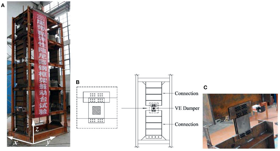
Figure 9. Test structure with VE damping device, (A) overall model on the table, (B) connection detail of the VE dampers, and (C) picture of an installed VE damper.
Implementation of the Numerical Model
The proposed mechanical model of VE damping device is created in a discrete numerical form in an open source finite element software—OpenSees (McKenna, 2011). The mechanical model is implemented as a uniaxial material, and VE dampers are modeled by two Node Link elements. It should be noted that the value of λ1 is 1.0 considering the ambient temperature is 22°C. For the mechanic model, to degrade its non-linearity and achieve a better convergence performance, the value of λ2 is taken as 0.9 and 0.7, respectively, for dampers installed in the first floor and second floor. The selection of λ2 value also considers the difference in deformation and fatigue damage.
The tested three-story steel frame structure can be modeled as a shear-type multi-degree of freedom (MDOF) system. The concentrated mass for 1st−3rd floor are 2517, 2671, and 2606 kg. The shear stiffness for 1st to 3rd floor are 0.682, 0.367, and 2.864 kN/mm. The modal results between the numerical and physical models are also compared to verify the accuracy of the establishment of the numerical model. The first 3 order natural frequency error between the two models can be controlled within 1.5%.
Verifications Via Shake Table Tests
The numerical simulation is performed in the OpenSees platform according to the test cases, and the mechanical model is fundamentally verified by comparing the simulation results with the test data. The mechanic behaviors of the VE damping devices are shown in Figure 10. Typical hysteresis behaviors are compared under maximum input value of 0.3 g for the first floor and 0.4 g peak input for the second floor. It is concluded that for most cases, the test curves and the numerical modeling result can correlate well. Except for the second floor under Taft input-0.4 g, the significant connection bolt slide is the main reason for the difference.
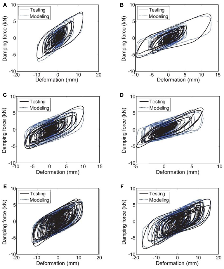
Figure 10. Hysteresis curve comparison between shake table test and numerical modeling for (A) 1st floor-El Centro-0.3 g, (B) 2nd floor-El Centro-0.4 g, (C) 1st floor-Taft-0.3 g, (D) 2nd floor-Taft-0.4 g, (E) 1st floor-AW-0.3 g, and (F) 2nd floor-AW-0.4 g.
The time history response of the relative acceleration and displacement at the top of the test model under AW input with 0.6 g peak input acceleration are shown in Figure 11. The time history response comparison confirms a good shape agreement between the test and numerical modeling during the integral input process. The time history comparison is not presented in detail. Instead, the maximum response of the floor acceleration and floor displacement under different input level and different earthquake waves are shown in Figures 12, 13. Results indicate that, with the increase of the peak input acceleration, the numerical modeling get closer to the real physical tests. The reason is that the other disturbances become less significant compared to the earthquake-induced response. Another observation is that the displacement simulation result is closer to the test data compared to the acceleration simulation. In general, the simulation results closely match the test data, regarding the time history response and peak values. It is concluded that the proposed mechanic model can be used to accurately represent the mechanic property of the new VE damping device under both static and dynamic loading.
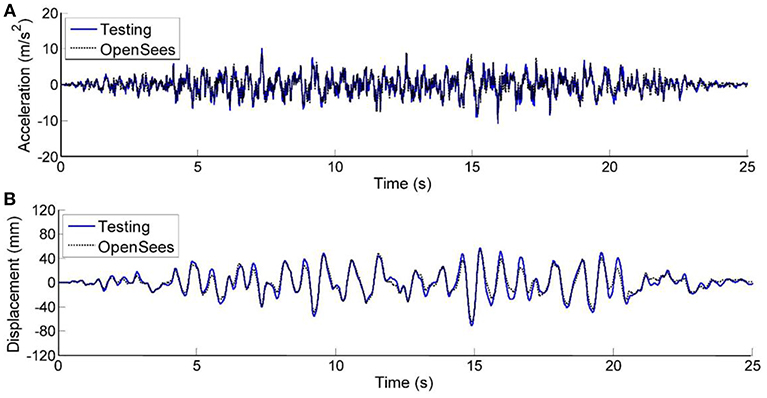
Figure 11. Comparison between OpenSees and test result under AW-0.6 g wave of (A) acceleration time history, and (B) displacement time history.
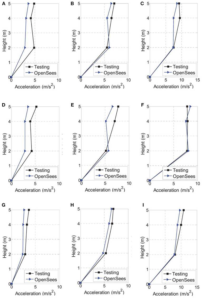
Figure 12. Peak floor acceleration response comparison under input of (A) El Centro-0.2 g, (B) El Centro-0.4 g, (C) El Centro-0.6 g, (D) Taft-0.2 g, (E) Taft-0.4 g, (F) Taft-0.6 g, (G) AW-0.2 g, (H) AW-0.4 g, and (I) AW-0.6 g.
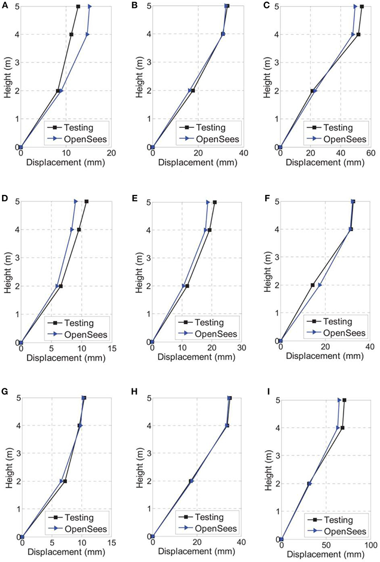
Figure 13. Peak floor displacement response comparison under input of (A) El Centro-0.2 g, (B) El Centro-0.4 g, (C) El Centro-0.6 g, (D) Taft-0.2 g, (E) Taft-0.4 g, (F) Taft-0.6 g, (G) AW-0.2 g, (H) AW-0.4 g, and (I) AW-0.6 g.
Conclusions
This paper presents a new VE damping device with hybrid non-linearity. The different sources of non-linearity are analyzed and an accurate mechanic model which can consider multi-non-linear behavior is proposed and validated via performance tests and shake table tests. The main conclusions from this study are as follows:
Five sources of non-linearity of this new VE damping device are summarized, including the non-linearity of phase difference, initial stiffness, softening caused by temperature rise and low-cycle fatigue, and the softening and hardening under large strain amplitude.
A seven-parameter mechanic model which considers the multi-non-linear behaviors is proposed based on the performance tests. The mechanic model is first verified by comparing the simulation hysteresis curves with the performance tests.
The mathematic mechanic model is implemented in a discrete numerical form in an open source calculation platform to apply the mechanic model into practical numerical calculation use. A series of shake table tests on a steel frame with the new VE dampers are performed as a comparison.
The shake table test results, regarding the VE damper hysteresis loops, time history response, and the floor peak response are compared with numerical simulation. The test results are in good agreement with the simulation results which prove the accuracy of the proposed mechanic model and the practical application of the numerical model.
Author Contributions
YZ contributed conception and design of the study. YZ and SG performed the tests. PC write the first draft manuscript. YZ and PC contributed to manuscript revision, read, and approved the submitted version.
Conflict of Interest Statement
The authors declare that the research was conducted in the absence of any commercial or financial relationships that could be construed as a potential conflict of interest.
Acknowledgments
The authors acknowledge the finical support from National Natural Science Foundation of China (Grant No. 51678449) and the Key innovation team program of innovation talents promotion plan by MOST of China (No. 2016RA4059).
References
Aiken, I. D., Nims, D. K., Whittaker, A. S., and James, M. K. (1993). Testing of passive energy dissipation systems. Earthquake Spectr. 9, 335–370. doi: 10.1193/1.1585720
Chang, K. C., Soong, T. T., Oh, S. T., and Lai, L. (1995). Seismic behavior of steel frame with added viscoelastic dampers. J. Struct. Eng. 121, 1418–1426. doi: 10.1061/(ASCE)0733-9445(1995)121:10(1418)
Chang, K. C., Soong, T. T., Oh, S. T., and Lai, M. L. (1992). Effect of ambient temperature on viscoelastically damped structure. J. Struct. Eng. 118, 1955–1973. doi: 10.1061/(ASCE)0733-9445(1992)118:7(1955)
Crosby, P., Kelly, J., and Singh, J. P. (1994). “Utilizing visco-elastic dampers in the seismic retrofit of a thirteen story steel framed building,” in Structures Congress X. I. I. ASCE (Atlanta, GA), 1286–1291.
Dall'Asta, A., and Ragni, L. (2006). Experimental tests and analytical model of high damping rubber dissipating devices. Eng. Struct. 28, 1874–1884. doi: 10.1016/j.engstruct.2006.03.025
Diani, J., Fayolle, B., and Gilormini, P. (2009). A review on the mullins effect. Eur. Polym. J. 45, 601–612. doi: 10.1016/j.eurpolymj.2008.11.017
Ghaemmaghami, A. R., and Kwon, O. S. (2018). Non-linear modeling of MDOF structures equipped with viscoelastic dampers with strain, temperature and frequency-dependent properties. Eng. Struct. 168, 903–914. doi: 10.1016/j.engstruct.2018.04.037
Gong, S., and Zhou, Y. (2017). Experimental study and numerical simulation on a new type of viscoelastic damper with strong non-linear characteristics. Struct. Control Health Monit. 24:e1897. doi: 10.1002/stc.1897
Gong, S., Zhou, Y., and Ge, P. (2017). Seismic analysis for tall and irregular temple buildings: a case study of strong non-linear viscoelastic dampers. Struct. Design Tall Special Build. 26:e1352. doi: 10.1002/tal.1352
Imbimbo, M., and Kelly, J. M. (1998). Influence of material stiffening on stability of elastomeric bearings at large displacements. J. Eng. Mechan. 124, 1045–1049. doi: 10.1061/(ASCE)0733-9399(1998)124:9(1045)
Kikuchi, M., and Aiken, I. D. (1997). An analytical hysteresis model for elastomeric seismic isolation bearings. Earthquake Eng. Struct. Dynam. 26, 215–231. doi: 10.1002/(SICI)1096-9845(199702)26:2<215::AID-EQE640>3.0.CO;2-9
Lai, M. L., Chang, K. C., Soong, T. T., Hao, D. S., and Yeh, Y. C. (1995). Full-scale viscoelastically damped steel frame. J. Struct. Eng. 121, 1443–1447. doi: 10.1061/(ASCE)0733-9445(1995)121:10(1443)
Lai, M. L., Lu, P., Lunsford, D. A., Kasai, K., and Chang, K. C. (1996). “Viscoelastic damper: a damper with linear or non-linear material,” in Proceedings of 11th World Conference on Earthquake Engineering (Acapulco).
Lewandowski, R., and Chora̧życzewski, B. (2010). Identification of the parameters of the Kelvin–Voigt and the Maxwell fractional models, used to modeling of viscoelastic dampers. Comput. Struct. 88, 1–17. doi: 10.1016/j.compstruc.2009.09.001
Mahmoodi, P., Robertson, L. E., Yontar, M., Moy, C., and Feld, L. (1987). “Performance of viscoelastic dampers in world trade center towers.” in Dynamics of Structures ASCE (Orlando, FL), 632–644.
McKenna, F. (2011). OpenSees: a framework for earthquake engineering simulation. Comput. Sci. Eng. 13, 58–66. doi: 10.1109/MCSE.2011.66
Molinera, E., Muserosb, P., and Martinez-Rodrigoa, M. D. (2012). Retrofit of existing railway bridge of short to medium spans for high-speed traffic using viscoelastic dampers. Eng. Struct. 40, 519–528. doi: 10.1016/j.engstruct.2012.03.016
Mullins, L. (1969). Softening of rubber by deformation. Rubber Chem. Technol. 42, 339–362. doi: 10.5254/1.3539210
Pant, D. R., Montgomery, M., and Christopoulos, C. (2018). Full-scale testing of a viscoelastic coupling damper for high-rise building applications and comparative evaluation of different numerical models. J. Struct. Eng. 145:04018242. doi: 10.1061/(ASCE)ST.1943-541X.0002246
Samali, B., and Kwok, K. C. S. (1995). Use of viscoelastic dampers in reducing wind-and earthquake-induced motion of building structures. Eng. Struct. 17, 639–654. doi: 10.1016/0141-0296(95)00034-5
Soong, T. T., and Spencer, B. F. Jr. (2002). Supplemental energy dissipation: state-of-the-art and state-of-the-practice. Eng. Struct. 24, 243–259. doi: 10.1016/S0141-0296(01)00092-X
Wu, C. X., Lai, W. S., Zhou, Y., Zhang, C., and Deng, X. (2015). Experimental study on seismic behaviors of new energy-dissipative prefabricated concrete frame structure joints. China Civil Eng. J. 48, 23–30. doi: 10.15951/.tmgcxb.2015.09.003 (in Chinese)
Xu, Z. D. (2009). Horizontal shaking table tests on structures using innovative earthquake mitigation devices. J. Sound Vib. 325, 34–48. doi: 10.1016/j.jsv.2009.03.019
Xu, Z. D., Guo, Y. F., Wang, S. A., and Huang, X.-H. (2013). Optimization analysis on parameters of multi-dimensional earthquake isolation and mitigation device based on genetic algorithm. Nonlinear Dyn. 72, 757–765. doi: 10.1007/s11071-013-0751-9
Xu, Z. D., Huang, X. H., and Lu, L. H. (2011). Experimental study on horizontal performance of multi-dimensional earthquake isolation and mitigation devices for long-span reticulated structures. J. Vibr. Control 18, 941–952. doi: 10.1177/1077546311418868
Xu, Z. D., Liao, Y. X., Ge, T., and Xu, C. (2016). Experimental and theoretical study of viscoelastic dampers with different matrix rubbers. J. Eng. Mech. 142:04016051. doi: 10.1061/(ASCE)EM.1943-7889.0001101
Xu, Z. D., Shen, Y. P., and Guo, Y. Q. (2003a). Semi-active control of structures incorporated with magnetorheological dampers using neural networks. Smart Mater. Struct. 12:80. doi: 10.1088/0964-1726/12/1/309
Xu, Z. D., Shen, Y. P., and Zhao, H. T. (2003b). A synthetic optimization analysis method on structures with viscoelastic dampers. Soil Dyn. Earthquake Eng. 23, 683–689. doi: 10.1016/j.soildyn.2003.07.003
Xu, Z. D., Zhao, H. T., and Li, A. Q. (2004). Optimal analysis and experimental study on structures with viscoelastic dampers. J. Sound Vib. 273, 607–618. doi: 10.1016/S0022-460X(03)00522-4
Yokota, H., Saruta, M., Nakamura, Y., Saruta, M., and Wada, A. (1992). “Structural control for seismic load using viscoelastic dampers.” in Proceedings of 10th WCEE (Madrid).
Keywords: viscoelastic material, hybrid non-linearity, mechanic model, non-linear analysis, shake table test
Citation: Zhou Y, Chen P and Gong S (2019) Mechanical Model of a Hybrid Non-linear Viscoelastic Material Damping Device With Its Verifications. Front. Mater. 6:33. doi: 10.3389/fmats.2019.00033
Received: 24 November 2018; Accepted: 14 February 2019;
Published: 05 March 2019.
Edited by:
Zhao-Dong Xu, Southeast University, ChinaReviewed by:
Peng Pan, Tsinghua University, ChinaIonut Ovidiu Toma, Gheorghe Asachi Technical University of Iasi, Romania
Copyright © 2019 Zhou, Chen and Gong. This is an open-access article distributed under the terms of the Creative Commons Attribution License (CC BY). The use, distribution or reproduction in other forums is permitted, provided the original author(s) and the copyright owner(s) are credited and that the original publication in this journal is cited, in accordance with accepted academic practice. No use, distribution or reproduction is permitted which does not comply with these terms.
*Correspondence: Ying Zhou, eWluZ3pob3VAdG9uZ2ppLmVkdS5jbg==