 Ying-Qing Guo
 Wen-Han Xie
 Xingjian Jing
- 1Mechanical and Electronic Engineering College, Nanjing Forestry University, Nanjing, China
- 2Department of Mechanical Engineering, The Hong Kong Polytechnic University, Hong Kong, Hong Kong
The magnetorheological (MR) damping material is a kind of smart shock absorption material, and it can be made into MR dampers for reducing the vibration or dynamic response of structures. During the vibration mitigation control of structures with MR dampers, the displacement and acceleration responses are always concerned firstly because the displacement responses determine the safety of structures and, at the same time, the acceleration responses determine the comfort level of the human body staying in structures. That means, the control currents choice of MR dampers during the vibration process is a multi-objective optimization control problem. In this paper, the particle swarm optimization (PSO) algorithm is developed to control the displacement and acceleration responses simultaneously. Numerical analysis for a five-floor steel frame structure with one MR damper installed on each floor is carried out. Simulation results of the PSO control structure are compared with those of passive control (including the ON-control and the OFF-control) structures and the uncontrolled structure. Analysis results demonstrate that the PSO algorithm can reduce the displacement responses of the structure obviously and, at the same time, it can reduce the acceleration responses of the structure to a certain extent. Furthermore, the PSO algorithm reduces the seismic responses of structures more effectively than those of passive control structures.
Introduction
The magnetorheological (MR) damping material is a kind of smart shock absorption material, which was discovered by Jacob Rabinow at the US National Bureau of Standards in 1948 (Rabinow, 1948). The MR damping material is composed of carbonyl iron particles, a carrier liquid and some additives. Normally, it is a free-flowing liquid with a certain viscosity similar to that of motor oil. However, when subjected to a magnetic field, the liquid becomes viscoelastic solid. And the stronger the magnetic field, the harder the MR damping material becomes. That is, the yield stress of the MR damping material can be controlled very accurately by changing the intensity of the magnetic field. On the other hand, removing the magnetic field causes the solid MR damping material to once again become liquid. Furthermore, the change can occur in only a few milliseconds (Guo et al., 2017). MR dampers are developed to take advantage of these characteristics of MR damping material. Because of these properties, more and more researchers are attracted to develop MR clutches and automotive MR suspensions, etc. In the civil engineering field, MR dampers are used to reduce the dynamic responses of structures in earthquake excitation or in strong wind, cable-stayed bridges, and seismic protection.
After the MR damper is installed into the structure, its damping and stiffness will change the parameters of the structure itself and further affect the anti-vibration ability of the structure (Xu et al., 2013). However, the controllable damping and controllable stiffness of the MR damper are controlled by its control currents (or voltages), that is to say, one of the important factors determining the effect of its vibration reduction is how to effectively select control currents (or voltages) of the MR damper. Many control algorithms of control currents (or voltages) of MR dampers have been developed. A linear optimal controller based on acceleration feedback, named a semi-active clipped-optimal control strategy, was designed to adjust the control voltage of the MR damper (Dyke et al., 1996). Another acceleration feedback control method of seismic structures was used to realize vibration mitigation of structures successfully (Chung et al., 1998). An intelligent neuro-fuzzy control strategy was developed relying on the correlation between accelerations of the building (controller input) and voltage applied to the MR damper (controller output) (Schurter and Roschke, 2001). A non-clipping semi-active control method, a stochastic optimal control strategy, was proposed for randomly excited non-linear systems using semi-active MR dampers (Ying et al., 2002). An on-line real-time control method by using neural networks techniques for semi-active control of structures with MR dampers was proposed. This method considered the time-delay problem of semi-active control, which can solve distortion of the responses of structures (Xu et al., 2003). An inverse neural network model for MR dampers was established to adjust the control voltage of the MR damper to realize the semi-active control mode of structures with MR dampers (Wang and Liao, 2005). A fuzzy control algorithm with a neural network forecasting model was proposed. According to the structural dynamic response predicted by the neural network forecasting model, the fuzzy controller can update control currents of MR dampers (Guo et al., 2008). Combining with modified adaptive control, Phu et al. built an interval type 2 fuzzy model to obtain the desired damping force of a MR damper, and then realize the vibration control of a washing machine (Phu et al., 2014). A semi-active control method for a non-linear benchmark building with MR dampers included two parts. One an optimal compact Takagi-Sugeno-Kang fuzzy inverse model for the MR damper. The other is voltage regulator based on the maximum and minimum capacities of the MR damper at each time-step (Askari et al., 2016). An adaptive Fuzzy-PID controller was implemented to ensure that the MR damper performs well, even at varying frequencies (Nordin et al., 2018).
In this paper, the particle swarm optimization (PSO) algorithm is developed to control the displacement and acceleration responses simultaneously. Numerical analysis for a five-floor steel frame structure with one MR damper installed on each floor is carried out. Simulation results of the PSO control structure are compared with those of passive control (including the ON-control and the OFF-control) structures and the uncontrolled structure. Analysis results demonstrate that the PSO algorithm can reduce the displacement responses of the structure and obviously, at the same time, it can reduce the acceleration responses of the structure to a certain extent. Furthermore, the PSO algorithm reduces seismic responses of structures more effectively than those of passive control structures.
Controlled Structure Model
MR Damper Model
In this paper, the shear-valve type of the MR damper (Xu and Guo, 2006) is used for the structural seismic mitigation control, as shown in Figure 1. And the Bingham model of the MR damper is proposed by Phillips (1969), which is one of the classic models and equivalent to a friction component augmented by a Newtonian viscosity component, as shown in Figure 2 (Guo et al., 2008). The relationship between the stress and strain rate can be describe as Xu and Shen (2003)
where τ is the shear stress in the MR damping material; τy, the yielding shear stress can be adjusted by the magnitude of the external magnetic field; η is the Newtonian viscosity, which is independent of the external magnetic field; is the shear strain rate. The magnitude of the external magnetic field can be controlled by control currents, so τy is the function of control currents Ic as shown in Equation (2) (Xu et al., 2003). A1, A2, and A3 are coefficients of the MR damping material, and e is the natural constant. Based on Equation (1) the relationship between the force and displacement of the MR damper is (Xu and Guo, 2006),
where is frictional force; is damping coefficient; Ld and Ap are the effective length and the cross-sectional area of the piston; D represents the inner diameter of the outer cylinder and hd represents the gap between the piston and the outer cylinder, u(t) represents the relative displacement of the piston to the outer cylinder.
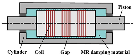
Figure 1. Schematic diagram of the shear-valve type MR damper.
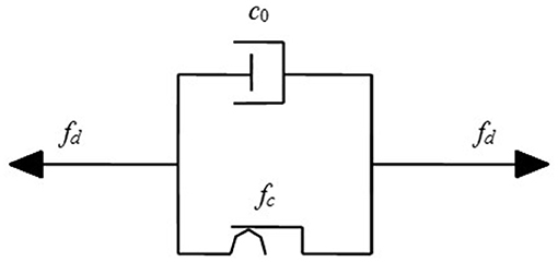
Figure 2. Bingham model (Guo et al., 2008).
Dynamic Equation of the Controlled Structure
In this paper, MR dampers are equipped between the chevron brace on each floor of the steel frame structure, as shown in Figure 3. The dynamic equation for the n-floor steel frame structure equipped MR dampers can be descripted as
where M, C, and K are the mass, damping, and stiffness matrixes of the steel frame structure, respectively; x is an n-dimensional vector to represent the displacement response of each floor of the steel frame structure relative to the ground; I is an n-dimensional column vector with 1 for each element; is the seismic acceleration; B is an n-dimensional vector to show the number of MR dampers installed on each floor of the steel frame structure; fd is an n-dimensional vector of control forces generated by MR dampers at each floor.
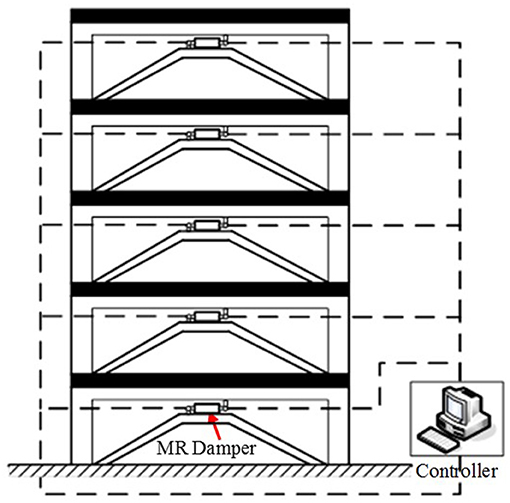
Figure 3. The structure with MR dampers.
Particle Swarm Optimization Algorithm
Based on the social behavior of bird flocking, fish schooling, and swarming theory, James Kennedy and Russell Eberhart proposed PSO algorithm in 1995 (Eberhart and Shi, 2001). That means, the birds in the group are abstracted into “particles” without mass and volume. Through the mutual cooperation and information sharing of these “particles,” the speed of their movement is affected by the information of the historical movement status of the group and themselves. The historical optimal position affects the current motion direction and motion speed of the particles and can better coordinate the relationship between the particles themselves and the group motion, and find the optimal solution in a complex solution space.
The Original Version PSO Algorithm
In an m-dimensional problem space there is a particle swarm, and zi is the current position of the i-th particle; vi is the current velocity of the i-th particle; pi is the optimal position experienced by the i-th particle in the particle group, which is called the optimal position of the individual; pg is the optimal position of the all particles of the swarm that were experienced, which is called the global optimal position. Then the evolution equation of the original version PSO algorithm can be described as Eberhart and Shi (2001)
where the subscript j means the j-th dimension of the particle; the subscript i means the i-th particle in the particle swarm; t is the t-th generation; c1 represents the cognitive learning coefficient which is used to adjust the step of particle that flies toward the best location of itself; c2 represents the social learning coefficient which is used to adjust the step of a particle that flies toward the global best position; rand1( ) and rand2( ) are two independent random functions within the range of [0,1].
The PSO Algorithm With Constriction Factor
In order to control the flying speed of the particle effectively and let the algorithm achieve a balance between global detection and particle exploitation, that is, in order to ensure convergence of the particle swarm algorithm, in 1999, Clerc proposed the PSO algorithm with constriction factor (Clerc, 1999). In 2000, Eberhart and Shi simplified the constriction factor and enhanced its practicality (Eberhart and Shi, 2000). The velocity evolution equation of the particle swarm algorithm with constriction factor can be described as
where k represents constriction factor which is a function of c1 and c2.
PSO Algorithm Design of MR Intelligent Structure
In the earthquake mitigation control of an MR intelligent structure, choosing a reasonable control current for the MR damper is key to reducing seismic damage to the structure. The displacement and acceleration responses of the MR intelligent structure can reflect whether the structure will be damaged or not. In this case, the displacement, and acceleration responses control constitute a multi-objective control system in the seismic mitigation control of the MR intelligent structure. The following is a detailed description of how to use the PSO algorithm to accurately select control currents of MR dampers, and then achieve multi-objective control of the MR intelligent structure and meet the requirements of building codes.
Definition of Fitness Function
In the PSO control of an MR intelligent structure, a multi-objective optimal control algorithm is adopted, that is, structural displacement targets, and structural acceleration targets. Therefore, the fitness function, namely the objective function can be set as:
where f1(t) is the objective function of the structural displacement; f2(t) is the objective function of the structural acceleration; α and β are weighting coefficients and α + β = 1; t represents the t-th moment; xn represents the n-th floor displacement of the structure; ẍn represents the n-th floor acceleration of the structure; Maxxn and Maxẍn are the maximum allowable displacement and acceleration response of the n-th floor of the structure.
It can be seen from Equation (9) that weighting coefficients α and β determine the weight relationship between the displacement target and the acceleration target in fitness function. According to the seismic requirements buildings and building codes, during the earthquake, the magnitude of the structural displacement is closely related to the safety of structures, which is the main control target. The structural acceleration is mainly to affect the safety of the internal furniture or equipment of the structure, which is the secondary control target. So, in general, 0 ≤ β < α ≤ 1.
In Equation (10), according to the seismic requirements buildings and building codes (China Building Code Compilation Group, 2001), Maxxn can be determined. When the structure is in an elastic state, the structural maximum inter-story displacement response is h/550 (h is the floor height of the structure), so Maxxn can be set as h/550 in the fitness function. When the structure is in an elastoplastic state, the structural maximum inter-story displacement is h/50.
Choice of PSO Algorithm
In the PSO control of the MR intelligent structure, the PSO algorithm with constriction factor proposed by Clerc (1999) was chosen, as shown in the Equation (3) and (4). The constriction factor k in the algorithm is more effective in controlling and constraining the flight speed of the particles, at the same time, enhancing the local search ability of the algorithm (Eberhart and Shi, 2000).
Termination Condition Setting of PSO Algorithm
In the PSO control of the MR intelligent structure, the termination condition of the PSO algorithms is whether the structural displacement response and the acceleration response meet the seismic requirements buildings and building codes. That is, when the displacement response and the acceleration response are less than the preset maximum value, the search for the optimal solution can be terminated, and the corresponding control current (or voltage) value of the MR damper is output. The setting of the termination conditions can not only ensure the safety of building structures but also ensure the rapid selection of the control current (or voltage) of the MR damper.
Numerical Analysis
Modeling and simulation analysis of a five-floor steel frame structure with one MR damper installed on each floor are carried out in MATLAB to verify the correctness and effectiveness of the designed PSO algorithm. The parameters of the five-floor steel frame structure are the each-floor mass: m = [2.60 2.30 2.30 2.30 2.30] × 104 kg; the each-floor initial stiffness: k = [2.06 2.32 2.32 2.32 2.32] × 107 N/M; the each floor height: h = [3.9 3.3 3.3 3.3 3.3] m. The Newtonian viscosity η is 0.9 Pa· s (Yang et al., 2002) in the Equation (1). Parameters in the Equation (2) are A1 = -11374, A2 = 14580, and A3 = 1281. Parameters in the equation (3) are Ld = 400 mm, hd = 2 mm, and D = 100 mm. Parameters of the designed PSO algorithm are: the size of particle swarm is 30, the particle dimension is 5, the weighting coefficient in fitness function α = 0.7 and β = 0.3, the cognitive learning coefficient c1 = 2.8, the social learning coefficient c2 = 1.3. El-Centro seismic waves and Taft seismic waves with 200 gal acceleration amplitude are selected, and the sampling time is 0.02 s.
In the numerical analysis, El Centro seismic waves first are used for the seismic excitation of different structures, and the seismic responses of the PSO control structure are compared with those of the passive control structures and the uncontrolled structure. Figure 4 shows the structural 5th floor responses of the PSO control and the uncontrolled structure. It can be obtained from Figure 4 that under the PSO algorithm the structural displacement and acceleration responses of the structure both are effective. Under the PSO algorithm, the structural 5th floor maximum displacement response is 19.3 mm, which is effectively reduced by 66.43% compared to that of the uncontrolled structure, 57.5 mm. And under the PSO algorithm, the structural 5th floor maximum acceleration response, 5.90 m/s2, is reduced by 10.58% compared to that of the uncontrolled structure, 6.60 m/s2. That is because, in order to ensure the safety of the structure, it is necessary to increase the stiffness of the MR damper by increasing the control currents of the MR damper to reduce the structural displacement responses. It means the more stiffness increases, the more displacement response decreases. But when the stiffness is increased, the structural acceleration responses will also be affected. Moreover, the large stiffness will lead to the increase of the structural acceleration response frequency and excessive stiffness will lead to the amplification of acceleration amplitude. That is, the large stiffness is unfavorable to the control of structural acceleration responses.
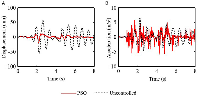
Figure 4. The structural 5th floor response of the PSO control and the uncontrolled structure (El-Centrol). (A) The displacement response. (B) The acceleration response.
To further illustrate the effectiveness of the PSO algorithm, the structural displacement and acceleration responses of the PSO control structure are compared with those of the ON-control structure and the OFF-control structure. The ON-control method and the OFF-control method belong to the passive control method. For the control current of the MR damper, when it is set as the maximum current level (2A), the control method is the ON-control method; when it is set as the minimum current level (0A), the control method is the OFF-control method. Figure 5 shows the structural 5th floor responses of the PSO control and the ON-control structure. Figure 6 shows the structural 5th floor responses of the PSO control and the OFF-control structure.
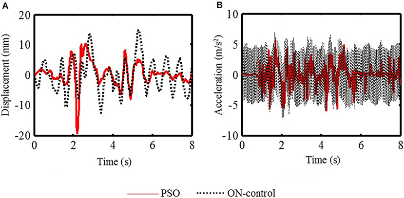
Figure 5. The structural 5th floor response of the PSO control and the ON-control structure (El-Centrol). (A) The displacement response. (B) The acceleration response.
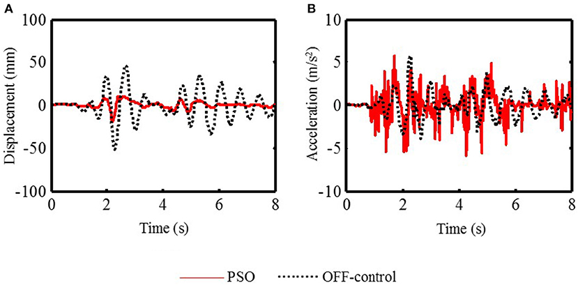
Figure 6. The structural 5th floor response of the PSO control and the OFF-control structure (El-Centrol). (A) The displacement response. (B) The acceleration response.
It can be obtained from Figure 5 that the displacement responses of the PSO control structure are inferior to those of the ON-control structure. However, the acceleration responses of the PSO control structure are far superior to those of the ON-control structure. Under the PSO algorithm, the structural 5th floor maximum displacement response is 19.3 mm, which is effectively reduced by −30.40% compared to that of the uncontrolled structure, 14.8 mm. But under the PSO algorithm, the structural 5th floor maximum acceleration response, 5.90 m/s2, is reduced by 17.11% compared to that of the uncontrolled structure, 7.12 m/s2. This is because under ON-control method the control currents applied to MR dampers are always the maximum current 2A, this inevitably makes the structural stiffness always very large. In this case, as mentioned above, the structural displacement responses must be significantly improved. However, the cost is that the frequency and amplitude of the structural acceleration responses are obviously amplified, which is not expected in the control process.
It can be obtained from Figure 6 that the displacement responses of the PSO control structure are significantly better than those of the OFF-control structure but the acceleration responses of the PSO control structure are not as much as those of the ON-control structure. Under the PSO algorithm, the structural 5th floor maximum displacement response is 19.3 mm, which is effectively reduced by 63.03% compared to that of the uncontrolled structure, 52.2 mm yet under the PSO algorithm, the structural 5th floor maximum acceleration response, 5.90 m/s2, is reduced by −2.61% compared to that of the uncontrolled structure, 5.75 m/s2.
Figure 7 shows the maximum seismic responses of each floor under different control methods. Table 1 lists the maximum displacement responses as a numeric comparison of each floor under different control methods. Table 2 lists the maximum acceleration responses as a numeric comparison of each floor under different control methods. It can be seen that for the displacement responses of each floor, the PSO control algorithm is slightly inferior to ON-control method, however, its shock absorption effect has reached the seismic requirements of the buildings and building codes and the reduced amplitude of each floor relative to the uncontrolled structure is also reduced by a minimum of 53.57%. For the maximum acceleration response of each floor, the ON-control method not only fails to reduce the maximum amplitude of each floor, but also causes a large scale-up. This is mainly due to the fact that the maximum current (2A) is always given to the MR damper in each floor under ON-control method, which makes the structural stiffness increase too much. Nonetheless, the PSO algorithm reduces the maximum acceleration of each floor to a certain extent because it can define more appropriate control currents according to the fitness function, which makes sure that structural displacement responses and acceleration responses are reduced as much as possible at the same time.
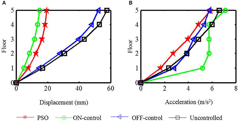
Figure 7. The maximum response comparison of each floor under different control method (El-Centrol). (A) The maximum displacement response. (B) The maximum acceleration response.
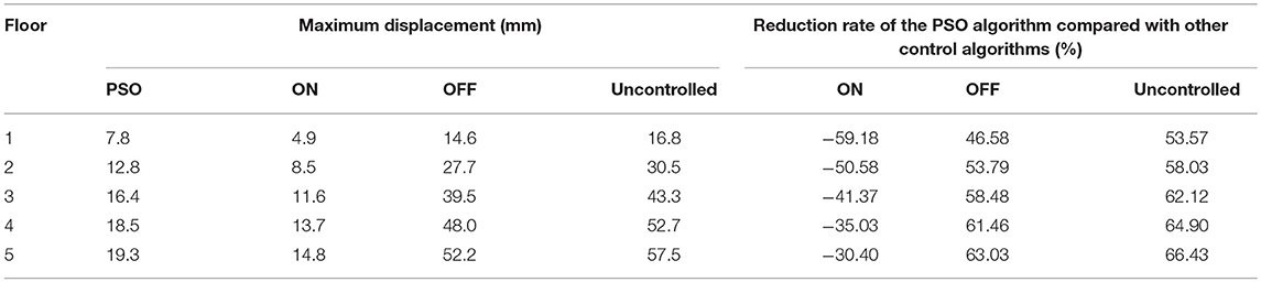
Table 1. The maximum displacement responses comparison of each floor (El-Centro).
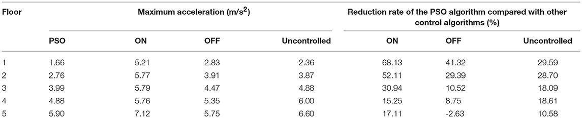
Table 2. The maximum acceleration responses comparison of each floor (El-Centrol).
Figure 8 shows control currents of MR dampers of each floor of the PSO control structure. Figure 9 shows control currents vs. forces of the 5th floor of the PSO control structure. It can be seen in Figure 8 that control currents applied to MR dampers at each time are completely different and most currents are <1.5A in most of the time. It can not only effectively reduce the damage to building structures caused by earthquakes, but also reduce energy waste as much as possible. It can be seen in Figure 9 that the amplitude of damping force produced by the MR damper increases with the increase of the control current. In addition, it can be seen that there are positive and negative damping forces, and sometimes there are different damping forces under the same control current such as 0.5A, because the damping force generated by the MR damper is related not only to the control current, but also to the speed of the MR damper at the current moment. Therefore, in the case of the same current, if the direction and/or magnitude of velocity is different, the damping force generated by the MR damper is also different.
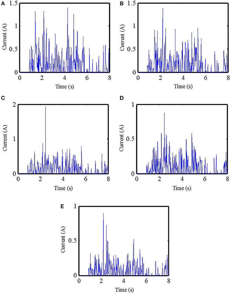
Figure 8. Control currents of MR dampers of each floor of the PSO control structure (El-Centrol). (A) The 1st floor control currents. (B) The 2nd floor control currents. (C) The 3rd floor control currents. (D) The 4th floor control currents. (E) The 5th floor control currents.
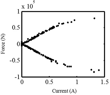
Figure 9. Control currents vs. forces of the MR damper of the 5th floor PSO control structure (El-Centrol).
When the earthquake excitation is changed, is the PSO control algorithm still valid? Taft seismic waves are used as the earthquake excitation to illustrate the effectiveness the PSO control algorithm under different the earthquake excitation. Figure 10 shows the maximum seismic responses of each floor under different control methods due to Taft earthquake. Table 3 lists the maximum displacement responses numeric comparison of each floor under different control methods. Table 4 lists the maximum acceleration responses numeric comparison of each floor under different control methods. It can be obtained that similar to El-Centro seismic excitation, for the displacement responses of each floor, the PSO control algorithm is slightly inferior to ON-control method, however, its shock absorption effect has reached the seismic requirements of buildings and building codes, moreover, and the reduced amplitude of each floor relative to the uncontrolled structure is also reduced by a minimum of 44.29%. For the maximum acceleration response of each floor, the PSO algorithm can reduce the maximum acceleration of each floor to a certain extent, and it works better than other methods.
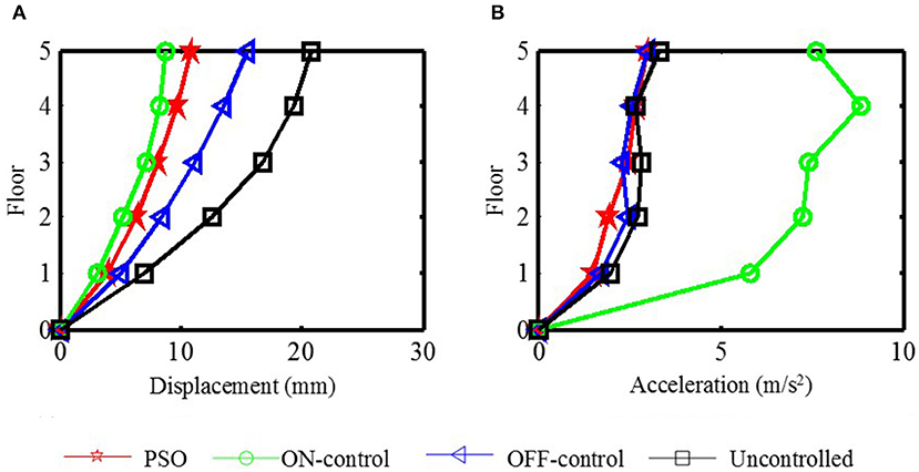
Figure 10. The maximum response comparison of each floor under different control method. (A) The maximum displacement response. (B) The maximum acceleration response.
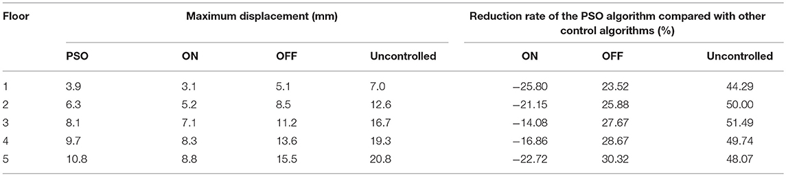
Table 3. The maximum displacement responses comparison of each floor (Taft).
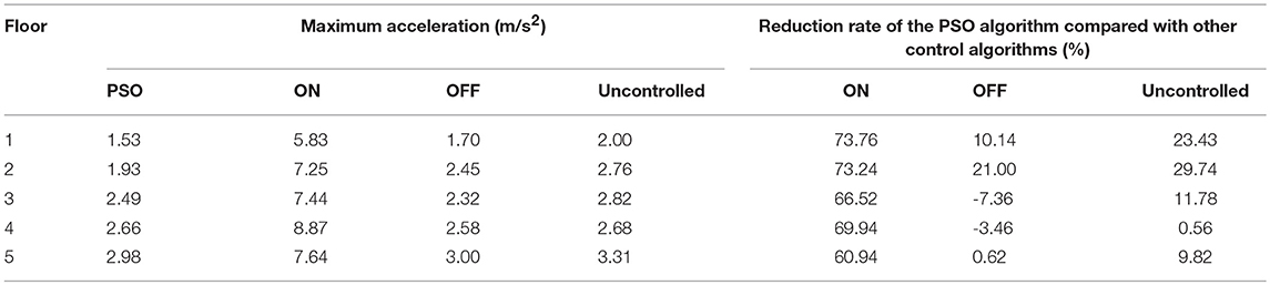
Table 4. The maximum acceleration responses comparison of each floor (Taft).
Concluding Remarks
In the PSO control of the MR intelligent structure, both the structural displacement and acceleration responses are the control objectives, so a multi-objective control algorithm is required. In this paper, the PSO algorithm as a multi-objective optimal control method for the MR intelligent structure is investigated, and numerical analysis for a five-floor structure with one MR damper installed on each floor under different seismic excitation is carried out. Simulation results of the PSO control structure are compared with those of the ON-control structure, the OFF-control structure and the uncontrolled structure. The following conclusions are obtained from this study.
In the seismic control of structures, the magnitude of structural displacement responses is related to the safety of building structures, and the structural acceleration responses are related to the destruction of the internal appendages and furniture of the structure, and even the safety of people in it. Therefore, the weighted sum of structural displacement and acceleration is selected as the fitness function in the PSO control algorithm. The simulation results show that the selection of the fitness function is reasonable and effective.
Whether with El Centro seismic waves or Taft seismic waves as the seismic excitation, under the PSO algorithm, the structural displacement responses can be significantly reduced, meanwhile the structural acceleration responses also can be reduced to some extent, while the reduced amplitude is relatively small. This is mainly because in the seismic control of building structures, the displacement control is more important than the acceleration control, the weight of the displacement is greater than that of the acceleration in the fitness function.
ON-control method can reduce the structural displacement responses very-well and the result is better than that of the PSO method. However, since the control current is always set to the maximum, the structural stiffness is always very large, and finally the structural acceleration responses is greatly amplified.
Data Availability
All datasets generated for this study are included in the manuscript and/or the supplementary files.
Author Contributions
Y-QG proposed the idea of this paper. Under the guidance, Y-QG and W-HX analyzed the PSO algorithm and jointly completed the writing of the article. XJ helped in proof reading of overall presentation and simulation data analysis.
Funding
The work was supported by National Natural Science Foundation of China with Grant Number (51878355), the National Science Fund for Distinguished Young Scholars with Grant number (51625803), the Program of Chang Jiang Scholars of Ministry of Education, Ten Thousand Talent Program of Leading Scientists and the Program of Jiangsu Province Distinguished Professor.
Conflict of Interest Statement
The authors declare that the research was conducted in the absence of any commercial or financial relationships that could be construed as a potential conflict of interest.
References
Askari, M., Li, J., and Samali, B. (2016). Semi-active control of smart building-MR damper systems using novel TSK-Inv and max-min algorithms. Smart Struct. Syst. 18, 1005–1028. doi: 10.12989/sss.2016.18.5.1005
China Building Code Compilation Group (2001). Code for Seismic Design of Buildings (GB50011-2001). Beijing: China building industry press.
Chung, L. L., Wu, L. Y., and Jin, T. G. (1998). Acceleration feedback control of seismic structures, Eng. Struct. 20, 62–74. doi: 10.1016/S0141-0296(97)00060-6
Clerc, M. (1999). “The swarm and the queen: towards a deterministic and adaptive particle swarm optimization,” in Proc. I999 ICEC, (Washington, DC), 1951–1957.
Dyke, S. J., Spencer, B. F., Sain, M. K., and Carlson, J. D. (1996). Modeling and control of magnetorheological dampers for seismic response reduction. Smart Mater. Struct. 5, 565–575. doi: 10.1088/0964-1726/5/5/006
Eberhart, R. C., and Shi, Y. (2000). “Comparing inertia weights and constriction factors in particle swarm optimization,” in Proceedings of the IEEE Conference on Evolutionary Computation (San Diego, CA: ICEC), 84–88.
Eberhart, R. C., and Shi, Y. (2001). “Particle swarm optimization: developments, applications and resources,” in Proc. Congress on Evolutionary Computation. IEEE service center, (Piscataway, NJ), 81–86.
Guo, Y. Q., Fei, S. M., and Xu, Z. D. (2008). Simulation analysis on intelligent structures with magnetorheological dampers. J. Intell. Mater. Syst. Struct. 19, 715–726. doi: 10.1177/1045389X07079650
Guo, Y. Q., Xu, Z. D., Chen, B. B., Ran, C. S., and Guo, W. Y. (2017). Preparation and experimental study of magnetorheological fluid for vibration control. Int. J. Acoust. Vibrat. 22, 1–7. doi: 10.20855/ijav.2017.22.2464
Nordin, N. H. D., Muthalif, A. G. A., and Razali, M. K. M. (2018). Control of transtibial prosthetic limb with magnetorheological fluid damper by using a fuzzy PID controller. J. Low Frequency Noise Vibrat. Active Control. 37, 1067–1078. doi: 10.1177/1461348418766171
Phillips, R. W. (1969). Engineering Applications of Fluids with a Variable Yield Stress, Ph.D. Thesis, university of California, Berkeley.
Phu, D. X., Shah, K., and Choi, S. B. (2014). Design of a new adaptive fuzzy controller and its implementation for the damping force control of a magnetorheological damper. Smart Mater. Struct. 23:065012. doi: 10.1088/0964-1726/23/6/065012
Rabinow, J. (1948). The magnetic fluid clutch. Transac. Am. Inst. Electr. Eng. 67, 1308–1315. doi: 10.1109/T-AIEE.1948.5059821
Schurter, K. C., and Roschke, P. N. (2001). “Neuro-fuzzy control of structures using magnetorheological dampers,” in Proceedings of the American Control Conference, (Arlington, VA), 1097–1102. doi: 10.1109/ACC.2001.945866
Wang, D. H., and Liao, W. H. (2005). Modeling and control of magnetorheological fluid dampers using neural networks. Smart Mater. Struct. 14, 111–126. doi: 10.1088/0964-1726/14/1/011
Xu, Z. D., and Guo, Y. Q. (2006). Fuzzy control method for earthquake mitigation structures with magnetorheological dampers. J. Intell. Mater. Syst. Struct. 17, 871–881. doi: 10.1177/1045389X06061044
Xu, Z. D., Sha, L. F., and Zhang, X. C. (2013). Design, performance test and analysis on magnetorheological damper for earthquake mitigation. Struct. Control Health Monit. 20, 956–970. doi: 10.1002/stc.1509
Xu, Z. D., and Shen, Y. P. (2003). Intelligent bi-state control for the structure with magnetorheological dampers. J. Intell. Mater. Syst. Struct. 14, 35–42. doi: 10.1177/1045389X03014001004
Xu, Z. D., Shen, Y. P., and Guo, Y. Q. (2003). Semi-active control of structures incorporated with magnetorheological dampers using neural networks. Smart Mater. Struct. 12, 80–87. doi: 10.1088/0964-1726/12/1/309
Yang, G., Spencer, B. F. Jr., Carlson, J. D., and Sain, M. K. (2002). Large-Scale MR fluid dampers: modeling and dynamic performance considerations, Eng. Struct. 24, 309–323. doi: 10.1016/S0141-0296(01)00097-9
Keywords: magnetorheological (MR) damping material, MR damper, the particle swarm optimization (PSO) algorithm, multi-objective optimization control, building structure
Citation: Guo Y-Q, Xie W-H and Jing X (2019) Study on Structures Incorporated With MR Damping Material Based on PSO Algorithm. Front. Mater. 6:37. doi: 10.3389/fmats.2019.00037
Received: 21 January 2019; Accepted: 20 February 2019;
Published: 19 March 2019.
Edited by:
Abid Ali Shah, University of Science and Technology Bannu, PakistanReviewed by:
Zhongwen Zhang, Southeast University, ChinaYeshou Xu, Northwestern University, United States
Xiangcheng Zhang, Zhengzhou University, China
Copyright © 2019 Guo, Xie and Jing. This is an open-access article distributed under the terms of the Creative Commons Attribution License (CC BY). The use, distribution or reproduction in other forums is permitted, provided the original author(s) and the copyright owner(s) are credited and that the original publication in this journal is cited, in accordance with accepted academic practice. No use, distribution or reproduction is permitted which does not comply with these terms.
*Correspondence: Ying-Qing Guo, Z3lpbmdxaW5nQDEyNi5jb20=