 Mikko Nelo
 Henrikki Liimatainen
 Maria Väätäjä1
 Jonne Ukkola
 Jari Juuti
 Heli Jantunen
- 1Microelectronics Research Unit, University of Oulu, Oulu, Finland
- 2Fiber and Particle Engineering, University of Oulu, Oulu, Finland
The frequency spectrum to be used by future wireless telecommunication systems such as 5G and beyond requires novel materials which are environment-friendly, are low cost and, most importantly, have low dielectric loss and permittivity when approaching higher frequencies. In this work, the development of all-inorganic composites with a relative permittivity of ~1.2 and loss tangents in the range of 10−3 is presented. The composites were fabricated at the exceptionally low temperature of 120°C and were based on lithium molybdate (Li2MoO4) ceramic as a water-soluble binder reinforced by quartz fibers. The relative permittivity was further decreased by the addition of hollow micron-sized glass spheres having very low dielectric loss. A simple manufacturing method through filtration, stencil printing and drying is presented. The microstructure of the composites was investigated with FESEM microscopy and the dielectric properties by SPDR. Printing tests were carried out in order to evaluate the possibility of using the proposed composites in, for example, printed antenna applications.
Introduction
The future telecommunication systems such as 5G will lead to new challenges to be solved: the increasingly high frequencies will increase the parasitic capacitances between the metal interconnects, the line-to-line crosstalk noise, the resistance—capacitance delay on the signal and the increased power dissipation (Maex et al., 2003; Shamiryan et al., 2004; Zhao et al., 2018). The use of low relative permittivity (εr) and low dielectric loss (tan δ) materials would minimize the parasitic capacitances, thus decreasing signal latency and allowing higher signal speeds and improved efficiency (Farrell et al., 2011). Low εr dielectric materials have been utilized in improving semiconductor packaging and integrated circuit performance as well as in high frequency, low-loss circuit boards (Shamiryan et al., 2004; Lee et al., 2005; Farrell et al., 2011). In polymeric materials both the use of porosity (Rathore et al., 2008; Joseph et al., 2015; Zhao et al., 2018) and low permittivity functional groups (Yuan et al., 2013; Liu et al., 2015; Lei et al., 2016) have been employed. Permittivity values as low as 1.05 with excellent dielectric losses have been achieved with porous polymeric materials such as the polyurethane and polyethylene foams as used in radomes (Eccostock product data sheet, 2018; General Plastics product data sheet, 2018).
Hollow glass microspheres (HGMS) offer an inexpensive solution to reducing the dielectric permittivity and losses of circuit boards or thick film devices (Kellerman, 1988; Chellis et al., 1992). Recently, coated glass microspheres have also been utilized in EM-shielding (Fu et al., 2007; Wang et al., 2016). Traditional solutions for making HGMS composites include a polymeric binder phase, although in this case the temperature stability is again a challenge.
Ceramic composite materials offer good stability at higher temperatures and their permittivity has been successfully reduced by introducing porosity (Bittner and Schmid, 2010; Sobocinski et al., 2015; Synkiewicz et al., 2017). Their downside has been the high manufacturing temperature resulting in high energy consumption and increased production costs. With the recent invention of a room temperature fabrication method (RTF), a water-based suspension of lithium molybdenum oxide (LMO), has been used to produce bulk dielectric samples and composites (Kähäri et al., 2014, 2015; Väätäjä et al., 2017). Using LMO enables a new approach to the manufacture of low εr ceramic materials at very low temperature due to its ability to form solid structures with 3D printing utilizing a low external pressure (Väätäjä et al., 2018). This enables the use of HGMS as a porosity-adding material without the risk of crushing them during molding. In this work, with the combination of the RTF method with its low pressure approach, a further development step is taken to achieve extremely low εr ceramic based composite materials.
Experimental
HGMS were purchased from Kevra Oy (Finland). According to the datasheet from the manufacturer, the spheres were C-type glass with 50–75% SiO2 and had an average particle size of 40–80 μm, a volumetric density of 0.1–0.15 g/cm3 and a temperature resistance of up to 650°C. Saturated Li2MoO4 (LMO) solution was made by mixing 80.0 g of LMO powder (>99%; Alfa Aesar, USA) in 100.0 g of deionized water overnight. The resulting saturated clear solution was collected and used in the experiments. The quartz fibers used were purchased from Robson Scientific (UK). According to the manufacturer, the fibers were quartz wool with a fiber diameter range of 5–30 μm, a purity of 99.995% SiO2 and a temperature resistance of up to 1,000°C.
Cellulose nanofibers (CNF) were synthesized from bleached birch-wood pulp (Betula Pendula) using a non-derivatizing urea-choline chloride deep eutectic solvent (DES) pre-treatment (Sirviö et al., 2015). First, the DES system was formed by heating 107.5 g choline chloride and 92.5 g urea in a round-bottom flask at 100°C in an oil bath to obtain a clear, colorless liquid, after which the cellulose fibers (2.0 g of dry sheets) were introduced into the liquid at 100°C for 2 h. After the DES pre-treatment, 200 ml of deionized water was added while mixing and the cellulose fibers were filtered (Whatman 413) and washed with deionized water (2,000 ml). The pretreated sample was further individualized into cellulose nanofibers using a microfluidizer (Microfluidics M-110EH-30, USA). The sample was diluted in a low concentration (0.5%) before microfluidization, and was then passed five times through 400 and 200 μm chambers at a pressure of 1,000 bar. The obtained viscous cellulose nanofiber suspension was stored in a cold environment (+4°C).
The samples were fabricated by the following method, inspired by the paper making process, but instead of cellulose fibers, 100 mg of quartz fibers were used to provide mechanical strength for the samples. The fibers were placed in a square format on a filter sheet using a 200 μm thick 60 × 60 mm stencil as a guide. They were moistened with deionized water to temporary bind them together. Two Hundred milligram of HGMS were mixed with 1.0 g of deionized water and 1.0 g of saturated LMO solution to form a paste. This paste was applied on top of the quartz fibers using a 100 μm thick, 50 × 50 mm sized stencil and a blade. The resulting sandwich-like structure was lifted from the filter and placed on a release film with the LMO-HGMS paste downwards, thus achieving a smooth surface. The second layer of LMO-HGMS paste was printed through the 100 μm stencil as in the previous step, resulting in samples with LMO-HGMS paste layers on both sides. A perforated plastic film was placed on top of the samples, followed by four layers of suction paper to absorb the excess LMO solution. Finally, the samples, release films and papers were placed between two aluminum plates, pressed using 2 kPa pressure and dried in an oven for 18 h at 110°C. The aluminum plates and additional pressure were used to avoid warping during drying. The resultant samples were treated with an additional 2 h of drying without the plates and pressure to ensure that all the water was evaporated.
The dimensions and weight of samples were measured after drying. Since the amounts of glass spheres and quartz wool were precisely known, the LMO content could be calculated from the weight of the samples. After the weighing, the samples were cut into 52 × 52 mm squares for density and dielectric measurements. Post-treatments for surface smoothening with CNF suspension or LMO solution were carried out after the first measurements. On post-treatment with CNF, 1.0 ml of 0.49 wt.% CNF suspension was spread on each side of the samples using a doctoring blade, and on post-treatment with LMO, 0.50 g of saturated solution and 0.5 g of deionized water was applied to both sides of the samples. Moistened samples were handled as in the original preparation step by drying them between smooth and perforated release films, suction papers, aluminum plates, and pressure for 18 h at 110°C followed by additional drying of 2 h freely at 110°C.
The printing tests of the conductive patterns were done by manually screen printing DuPont 5064H (DuPont Ltd, UK) silver ink through a 180 mesh nylon screen with 16 μm thick emulsion and 500 μm wide lines. The printed patterns were dried for 30 min at 120°C. The flow of the sample manufacturing process with a schematic drawing of the sample structure is presented in Figure 1.
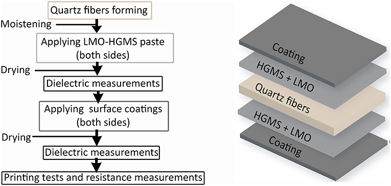
Figure 1. (Left) Flow diagram of sample preparation process. (Right) Structural layers of the samples.
The dielectric measurements were carried out with a vector network analyzer (VNA) (Rhodes and Schwarz ZVB20, Germany) with split-post dielectric resonators (SPDR) (QWED, Poland) with nominal resonances at 2,475 and 5,180 MHz. The measurement results were calculated using QWED analysis software developed for the resonators. The resistance of the printed conductive lines was measured using a four-point measurement carried out in a probe station (Wentworth Laboratories, USA) connected to a multimeter (Agilent Technologies 34401A, USA). The surface quality after different treatments and elemental composition was investigated with field emission scanning electron microscopy (FESEM-EDS) analysis (Carl Zeiss Ultra Plus, Germany). Finally, the surface roughness analysis was done with a 3D laser scanning microscope (Keyence VK-X200, USA).
Results and Discussion
The dielectric values for the coated samples are shown in Table 1. Untreated LMO-HGMS samples were measured before and after two different coatings. A total of six samples were measured in each case and the standard deviations calculated. The uncoated samples had an average relative permittivity of 1.19 and a loss tangent of 1.6–1.7 × 10⁻³ at both measurement frequencies, whereas the CNF coated samples had a permittivity of 1.19 with an increased loss tangent of 2.5–2.7 × 10⁻³. The small influence of the CNF coating on the permittivity was estimated to be caused by the small quantity of CNF needed to achieve a smooth surface; typically 10 mg per sample. However, the increased losses were probably caused by polar functional groups in the CNF coating. The LMO coated samples remained similar in their dielectric properties with only minor changes in both relative permittivity and loss tangent. This result is due to the low dielectric loss of LMO, thus leading to very small changes in dielectric properties.
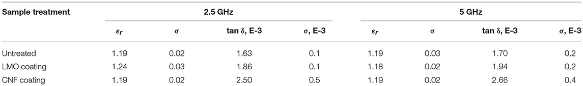
Table 1. Dielectric properties with standard deviation of samples at 2.5 and 5 GHz.
FESEM analysis was used to assess the surface quality of the samples. On uncoated samples (Figure 2a), it was noted that despite the gentle manufacturing process (maximum of 2 kPa pressure) some of the HGMS on the surface were cracked. This could be further improved by selecting smaller HGMS. Some quartz fibers were also visible on the surface. These caused some problems later in the printing experiments. Although the LMO was observed to bind most of the particles together, some porosity was observed on the sample surfaces. LMO and CNF coated samples (Figures 2b,c) had clearly reduced porosity, the latter being the least porous. CNF coating resulted in the smoothest surface, whereas LMO coating appeared to form crystals during the precipitation of LMO from the coating solution. EDS analysis (Figure 2d) was carried out on an uncoated sample to determine the SiO2 content of the HGMS beads. After reduction of LMO from the result, the HGMS contained 72 wt.% SiO2, 14 wt.% Na2O, and 14 wt.% CaO. Using reduced alkali HGMS could possibly further reduce the dielectric losses of the composite samples.
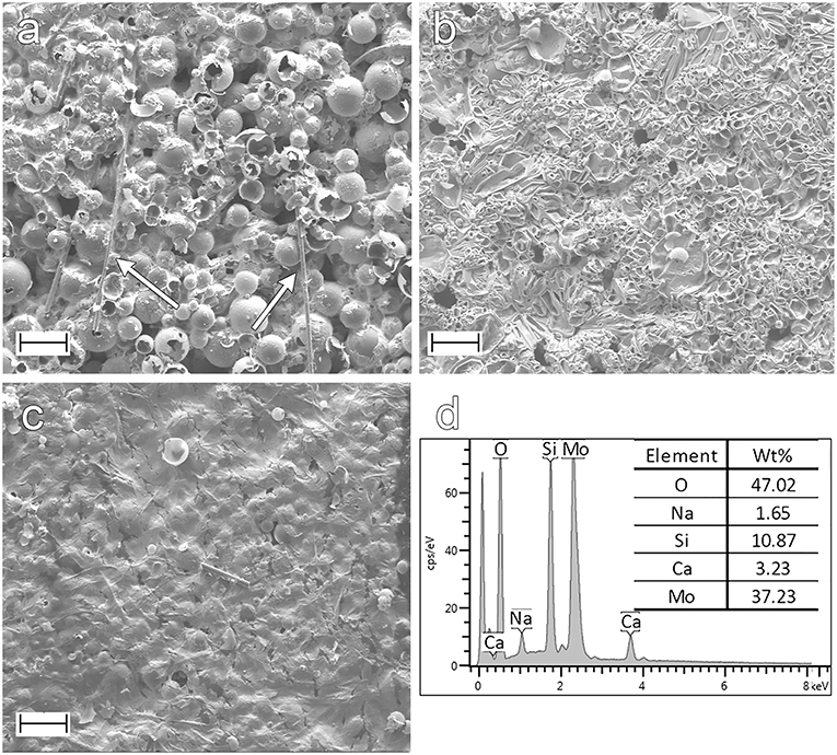
Figure 2. (a) Uncoated sample. The surface consisted of LMO- bound HGMS showing porosity and some quartz fibers (white arrows). (b) LMO-coating reduced the surface porosity and submerged fibers. The LMO was observed to form hexagonal patterns on the sample surface. (c) CNF coated sample showed the smoothest surface with only a minor amount of porosity visible. All scale bars 100 μm. (d) EDS analysis of uncoated sample surface showing molybdate and oxygen from the LMO and the other elements from the HGMS.
The roughness after different surface treatments was studied with 3D laser scanning microscope using 3 × 3 mm2 area of each sample. In addition, a common printing paper (Xerox, 80 g/m2), a sintered ceramic substrate (DuPont 951) and a PET sheet for printed electronics (Melinex 339 PET) were analyzed to compare the surface quality of the produced samples. The results collected in Figure 3 show that whereas LMO coating has a small effect, the utilization of CNF greatly reduces surface roughness. With further optimization, even smoother surface should be achievable.
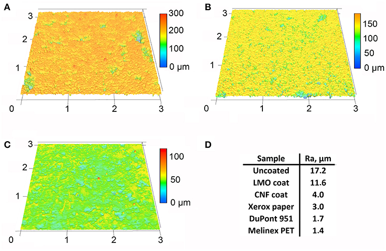
Figure 3. Surface profiles and roughness values for different samples. Zero height is set as the lowest point for each sample. (A) Uncoated sample with the highest roughness. (B) Sample with LMO-coating with lower roughness. (C) CNF coated sample with the smoothest surface of HGMS composites. (D) Surface roughness measured for the HGMS composite samples, printing paper, sintered ceramic substrate, and PET sheet.
The conductive lines were fabricated by screen printing. The high viscosity of the printing ink was considered to be beneficial when printing on a porous surface, while low viscosity inks could easily be completely absorbed into the samples. The printing proved to be challenging due to the contact that the printing screen made with the substrate despite the offset of the screen. In the untreated samples, loosely attached HGMS or quartz fibers adhered to the screen's surface. The same tendency was observed with the loose crystals on the LMO coated samples. This contaminated the printing surface of the screen and caused damage to the printed lines, as shown in Figures 4a,b. These problems were not present with CNF coated samples (Figure 4c), which resulted in more uniform printed patterns.
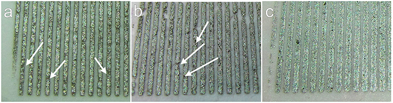
Figure 4. (a–c) Printed 500 μm wide test lines. (a) Sample with untreated surface, (b) sample with LMO coating, (c) sample with CNF coating. Damage (white arrows) on lines was observed in untreated and LMO coated samples.
The resistance values of the 4.0 mm long and 0.5 mm wide printed lines as determined by four-point measurement were compared with those of the patterns printed on PET sheet. Six parallel lines were measured and their resistance values and standard deviations are shown in Table 2. The results showed that the lines printed on CNF coated samples gave lower resistance values than those measured from uncoated and LMO coated samples. Moreover, these CNF coated samples exhibited very similar resistance values to those of the lines printed on the PET sheet. The feasibility of the silver ink used here has been earlier demonstrated for antenna operating at ~ 4 GHz (Kähäri et al., 2016).
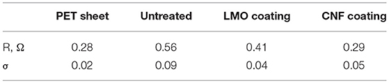
Table 2. Resistance of 4.0 × 0.5 mm2 printed lines.
Conclusions and Perspectives
A simple method of manufacturing extremely low εr ceramic based composite materials at very low temperature is presented. The composites showed low losses at high frequencies. In addition to this, a surface coating method was developed by utilizing LMO solution and CNF suspension for resulting in improved surface smoothness which enabled printing of conductive lines with low resistance. The composite with CNF coating exhibited εr and tan δ values of 1.19 and 0.0027 at 5 GHz, respectively. The lines printed on this composite showed a resistance of 0.29 Ω, similar to those printed on PET. The performance of the composite can be even further optimized in the future with lower alkali content or reduced size of HGMS, and different methods of surface coatings, such as applying sol-gel film on top of the samples.
The proposed method provides a simple approach to fabricate ceramic-based low εr substrates with only five processing steps starting from raw powder materials. The method is also environmentally friendly due to its low energy consumption achieved by low fabrication temperature (120°C) compared to the one commonly used for ceramics (>850°C). Moreover, since only low fabrication temperature and pressure are used, no special devices with high investment costs are required.
Author Contributions
MN produced and measured all the samples, obtained the used materials and developed the filtration-based manufacturing method. HL and JU prepared the nanocellulose used in surface treatments of the samples. MV operated the laser scanning microscope and assisted on measurement data processing. HJ and JJ formulated the original hypotheses and discussed the dielectric results and printing experiments of the study. All authors contributed to the writing of the manuscript and evaluation of the results.
Conflict of Interest Statement
The authors declare that the research was conducted in the absence of any commercial or financial relationships that could be construed as a potential conflict of interest.
Acknowledgments
The work leading to these results has received funding from the European Research Council (ERC) under the ERC POC grant agreement No. 812837. This work was supported in part by the Academy of Finland 6 Genesis Flagship (grant no. 318927) and by the Academy of Finland Printed Intelligence Infrastructure, PII (grant no. 320020).
References
Bittner, A., and Schmid, U. (2010). Permittivity of LTCC substrates porousified with a wet chemical etching process. Proce Eng. 5, 327–330. doi: 10.1016/j.proeng.2010.09.114
Chellis, L. N., Japp, R. M., Summa, W. J., Rudik, W. J., and Wang, D. W. (1992). Flame Retardant, Low Dielectric Constant Microsphere Filled Laminate. New York, NY: International Business Machines Corporation. Patent, US5126192A
Eccostock product data sheet (2018) Available online at: http://www.eccosorb.com/Collateral/Documents/English-US/RFP-DS-PP%20112515.pdf (accessed April 25, 2019).
Farrell, R., Goshal, T., Cvelbar, U., Petkov, N., and Morris, M.A. (2011). Advances in ultra low dielectric constant ordered porous materials. Electrochem. Soc. Interface Winter 20, 39–46. doi: 10.1149/2.F04114if
Fu, W., Liu, S., Fan, W., Yang, H., Pang, X., Xu, J., et al. (2007). Hollow glass microspheres coated with CoFe2O4 and its microwave absorption property. J. Magn. Magn. Mater. 316, 54–58. doi: 10.1016/j.jmmm.2007.03.201
General Plastics product data sheet (2018) https://www.generalplastics.com/wp-content/uploads/2016/11/White-Paper-PU-Foam-Dielectric-Materials-for-Use-in-Radomes-and-Other_Applications.pdf (accessed April 25, 2019).
Joseph, A. M., Nagendra, B., Surendran, K. P., and Gowd, E. B. (2015). Syndiotactic polystyrene/hybrid silica spheres of POSS siloxane composites exhibiting ultralow dielectric constant. ACS Appl. Mater. Interfaces 7, 19474–19483. doi: 10.1021/acsami.5b05933
Kähäri, H., Ramachandran, P., Juuti, J., and Jantunen, H. (2016). Room-temperature-densified Li2MoO4 ceramic patch antenna and the effect of humidity. Int. J. Appl. Ceram. Technol. 14, 50–55. doi: 10.1111/ijac.12615
Kähäri, H., Teirikangas, M., Juuti, J., and Jantunen, H. (2014). Dielectric properties of lithium molybdate ceramic fabricated at room temperature. J. Am. Ceram. Soc. 97, 3378–3379. doi: 10.1111/jace.13277
Kähäri, H., Teirikangas, M., Juuti, J., and Jantunen, H. (2015). Improvements and modifications to room-temperature fabrication method for dielectric Li2MoO4 ceramics. J. Am. Ceram. Soc. 98, 687–689. doi: 10.1111/jace.13471
Kellerman, D. (1988). Micro-Electronics Devices and Methods of Manufacturing Same. Maynard, MA: Digital Equipment Corporation. Patent US4781968A.
Lee, B., Park, Y.-H., Hwang, Y.-T., Oh, W., Yoon, J., and Ree, M. (2005). Ultralow-k nanoporous organosilicate dielectric fi lms imprinted with dendritic spheres. Nat. Mater. 4, 147–150. doi: 10.1038/nmat1291
Lei, X., Qiao, M., Tian, L., Chen, Y., and Zhang, Q. (2016). Tunable permittivity in high-performance hyperbranched polyimide films by adjusting backbone Rigidity. J. Phys. Chem. C 120, 2548–2561. doi: 10.1021/acs.jpcc.5b11667
Liu, Y., Qian, C., Qu, L., Wu, Y., Zhang, Y., Wu, X., et al. (2015). A bulk dielectric polymer film with intrinsic ultralow dielectric constant and outstanding comprehensive properties. Chem. Mater. 27, 6543–6549. doi: 10.1021/acs.chemmater.5b01798
Maex, K., Baklanov, M. R., Shamiryan, D., lacopi, F., Brongersma, S. H., and Yanovitskaya, Z. S. (2003). Low dielectric constant materials for microelectronics. J. Appl. Phys. 93, 8793–8841. doi: 10.1063/1.1567460
Rathore, J. S., Interrante, L. V., and Dubois, G. (2008). Ultra Low-k Films Derived from Hyperbranched Polycarbosilanes (HBPCS). Adv. Funct. Mater. 18, 4022–4028. doi: 10.1002/adfm.200801197
Shamiryan, D., Abell, T., Iacopi, F., and Maex, K. (2004). Low-k dielectric materials. Mater. Today 7, 34–39. doi: 10.1016/S1369-7021(04)00053-7
Sirviö, J. A., Visanko, M., and Liimatainen, H. (2015). Deep eutectic solvent system based on choline chloride-urea as a pre-treatment for nanofibrillation of wood cellulose. Green Chem. 17, 3401–3406. doi: 10.1039/C5GC00398A
Sobocinski, M., Teirikangas, M., Peräntie, J., Vahera, T., Nelo, M., Juuti, J., et al. (2015). Decreasing the relative permittivity of LTCC by porosification with poly(methyl methacrylate) microspheres. Ceram. Int. 41, 10871–10877. doi: 10.1016/j.ceramint.2015.05.028
Synkiewicz, B., Szwagierczak, D., and Kulawik, J. (2017). Multilayer LTCC structures based on glass-cordierite layers with different porosity. Microelectron 34, 110–115. doi: 10.1108/MI-12-2016-0084
Väätäjä, M., Kähäri, H., Juuti, J., and Jantunen, H. (2017). Li2MoO4 -based composite ceramics fabricated from temperature- and atmosphere-sensitive MnZn ferrite at room temperature. J. Am. Ceram. Soc. 100, 3626–3635. doi: 10.1111/jace.14914
Väätäjä, M., Kähäri, H, Ohenoja, K., Sobocinski, M., Juuti, J., and Jantunen, H. (2018). 3D printed dielectric ceramic without a sintering stage. Sci. Rep. 8:15955. doi: 10.1038/s41598-018-34408-5
Wang, J., Wang, J., Zhang, B., Sun, Y., Chen, W., and Wang, T. (2016). Combined use of lightweight magnetic Fe3O4-coated hollow glass spheres and electrically conductive reduced graphene oxide in an epoxy matrix for microwave absorption. J. Magn. Magn. Mater. 401, 209–216. doi: 10.1016/j.jmmm.2015.10.001
Yuan, C., Jin, K., Li, K., Diao, S., Tong, J., and Fang, Q. (2013). Non-porous low- k dielectric films based on a new structural amorphous fluoropolymer. Adv. Mater. 25, 4875–4878. doi: 10.1002/adma.201302021
Keywords: low permittivity, ceramic composites, nanocellulose, low temperature, GHz antenna application, electroceramic composites, electronics substrate
Citation: Nelo M, Liimatainen H, Väätäjä M, Ukkola J, Juuti J and Jantunen H (2019) Solid Air—Low Temperature Manufacturing of Ultra-Low Permittivity Composite Materials for Future Telecommunication Systems. Front. Mater. 6:94. doi: 10.3389/fmats.2019.00094
Received: 06 December 2018; Accepted: 15 April 2019;
Published: 03 May 2019.
Edited by:
Michael P. M. Jank, Fraunhofer Institut für Integrierte Systeme und Bauelementetechnologie IISB, GermanyReviewed by:
Janos Kiss, University of Szeged, HungaryAri Alastalo, VTT Technical Research Centre of Finland Ltd., Finland
Copyright © 2019 Nelo, Liimatainen, Väätäjä, Ukkola, Juuti and Jantunen. This is an open-access article distributed under the terms of the Creative Commons Attribution License (CC BY). The use, distribution or reproduction in other forums is permitted, provided the original author(s) and the copyright owner(s) are credited and that the original publication in this journal is cited, in accordance with accepted academic practice. No use, distribution or reproduction is permitted which does not comply with these terms.
*Correspondence: Mikko Nelo, bWlra28ubmVsb0BvdWx1LmZp