 Huanjun Jiang
 Shurong Li
 Liusheng He
- 1State Key Laboratory of Disaster Reduction in Civil Engineering, Tongji University, Shanghai, China
- 2Department of Disaster Mitigation for Structures, Tongji University, Shanghai, China
To enhance the seismic resilience of coupled reinforced concrete shear walls, a new damper working in the replaceable coupling beam is proposed in present study. The new damper is a combination of metallic damper and viscoelastic (VE) damper. The metallic damper consists of an I-shaped steel beam with multiple low-yield-point steel plate webs paralleled to each other; the VE damper is composed of multiple layers of VE material bonded between multiple steel plates. Through the composite use of viscoelastic material and low-yield-point steel, the new damper is expected to work effectively against both the earthquake and the wind. To study the respective mechanical behavior of each component of the combined new damper, eight metallic dampers, two VE dampers, and one combined damper are tested under cyclic loading first. The variable parameters of the metallic damper are strength grade of web steel, web dimensions, and end stiffener configuration. It is found that the effect of the strength grade of web steel is most significant. Compared with the metallic damper using the steel web with normal strength grade, the ductility, ultimate plastic shear rotation, and cumulative plastic shear rotation of the damper using the low-yield-point steel web are much larger. The effect of web dimensions on the deformation capacity is slight. With the addition of end stiffener, plasticity concentrates thereby, which prevents the flange-to-end plate weld fracture. The VE damper exhibits extraordinary deformability. The storage modulus, shear loss modulus and loss factor of the VE material decrease with the increase of strain amplitude. The storage modulus and shear loss modulus of the VE material decrease slightly as the excitation frequency increases within the range between 0.1 and 1 Hz, and the effect of the excitation on the loss factor is not significant. At last, the combined damper, an assembly of one metallic damper component and two VE damper components, is tested, which exhibits stable hysteretic behavior and excellent deformability. The predicted yield shear strength and elastic stiffness agree well with test results.
Introduction
Reinforced concrete shear walls are widely used in medium- and high-rise building structures due to their large capacity of axial/lateral strength and stiffness. As commonly adopted in practice, short coupling beams are used to connect adjacent walls to have an efficient structural wall system. In case of a damaging earthquake, coupling beams as the first defense level of the coupled wall system will undergo large deformation and dissipate most energy. Therefore, coupling beams concentrate most of the damage during earthquakes, which is difficult to repair (Kam and Pampanin, 2011; Wallace, 2012). Even if the coupling beams can be repaired, the cost of time and expense is great.
To solve the problem, several researchers have proposed various types of dampers installed within the coupling beam. Most of them belong to displacement-dependent dampers which provide high initial stiffness and exhibit significant energy-dissipation capacity, such as metallic yielding dampers and friction dampers. Fortney et al. (2007) developed a new steel coupling beam with a central fuse. Test results showed that the coupling beam demonstrated good energy-dissipation capacity. Chung et al. (2009) developed a friction damper that applied in the middle of coupling beams. A non-linear time history analysis was conducted, and the analysis results showed that the seismic performance of the coupled shear wall system with friction dampers was superior to the traditional coupled shear wall system. As the metallic damper is commonly cheaper and more reliable in terms of durability, a number of studies have been focused on them in recent years (Wang et al., 2012; Ji et al., 2016; Lu X. et al., 2018a,b; Lu Z. et al., 2018a,b). However, for the I-section steel damper, the filet welds between the web and the stiffener fractured, leading to the damper failure. For the I-section steel beam with a diamond-shaped opening in the web, the stress concentrated around the opening, and corners tore with the increase of shear rotation, causing the early failure of the damper (Lu X. et al., 2018a,b; Lu Z. et al., 2018a,b). Velocity-dependent devices such as viscoelastic (VE) dampers and viscous fluid dampers can dissipate energy for all magnitudes of dynamic deformation. Therefore, VE dampers were installed in the mid-span of the coupling beams (Montgomery and Christopoulos, 2015). Non-linear dynamic analysis of tall buildings incorporating VE dampers demonstrated good performance under wind and minor earthquakes, but the improvement was not obvious under major earthquakes (Mackay-Lyons et al., 2012).
Meanwhile, different types of seismic energy absorption devices have been developed, such as viscoelastic dampers, viscous dampers, metallic dampers, tuned mass dampers, earthquake isolation devices, magnetorheological dampers, particle mass dampers, and et al (Xu et al., 2013b, 2016; Jiang et al., 2017; Lu X. et al., 2018a,b; Lu Z. et al., 2018a,b). Through the optimization of placing these devices, the structural vibration can be largely reduced (Xu et al., 2003, 2004, 2013a, 2019). Among these devices, metallic dampers are increasingly used, such as X-shaped metal dampers (Tsai et al., 1993), shape memory alloy dampers (Wang and Zhu, 2017), bucking restrained braces (Takeuchi et al., 2012; Shi et al., 2018), steel slit shear walls (Hitaka and Matsui, 2003; Kurata et al., 2015; He et al., 2016), and among others. The reasons for their popularity include low cost, stable hysteretic behavior, good reliability and so on. A certain amount of dissatisfaction on metallic dampers is the relatively large lateral deformation needed to trigger the energy dissipation and thus the efficiency in dissipating energy is usually not desirable under minor earthquakes or wind excitation. While, VE dampers are known to be effective in controlling vibrations under small ground motions. However, the stiffness they provide is limited and damping is not sufficient when experiencing strong earthquakes. Naturally, the idea comes that a proper combination of metallic dampers and VE dampers used in coupling beams might give satisfactory performance for the coupled shear wall system under both minor and strong earthquakes.
With the above background, a new combined damper installed in the mid-span of coupling beams is proposed in this paper. The new damper is a combination of the VE damper and metallic damper, so as to achieve vibration control demands under different excitation levels. A series of cyclic loading tests were carried out to gain a better understanding of the mechanical behavior of the combined damper. Comparative investigations on the failure mode, shear strength, hysteretic behavior, ductility, and energy dissipation etc. were conducted using test results.
Description of New Combined Damper for Replaceable Coupling Beams
Figure 1A shows the schematic diagram of the replaceable coupling beam, which comprises of the new replaceable damper in the middle and non-replaceable parts at two ends of the coupling beam. In case of an earthquake, damage is expected to be concentrated on the combined damper and the non-replaceable parts remain elastic. Figure 1B shows the schematic drawing of the combined damper, which is the combination of one central metallic damper and two edge VE dampers. The metallic damper is an I-shaped steel beam with two steel plate webs placed in parallel, which were welded together by complete joint penetration groove welds. The VE damper consists of multiple layers of VE materials bonded between multiple steel plates.
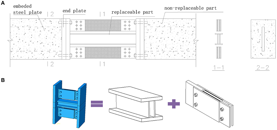
Figure 1. Schematic drawing: (A) replaceable coupling beam; (B) the combined damper.
Previous studies suggested that it was preferred to have the metallic damper yielding in shear because of its stable behavior under cyclic loading (Okazaki and Engelhardt, 2007). Meanwhile, studies also showed that for the web with stiffeners, the shear strains were observed to increase near the web stiffeners. In contrast, for web without stiffeners the distribution of strains was more uniform along the length (Dusicka et al., 2009). Therefore, to avoid web buckling, trying to have a smaller web depth-thickness ratio of the web through reducing height or increasing thickness was adopted in this study. Meanwhile, end plate stiffener was also used in one metallic damper for comparison.
Test Program
Test Specimens
Eight metallic dampers, two VE dampers and one combined damper were designed, the dimensions of which are illustrated in Figure 2. For the metallic damper, the variable parameters studied are the steel grade, dimensions of the web, and end stiffener configuration. Q345 steel, one kind of Chinese standardized mild steel with the yield strength of 345 MPa, is used for flanges. For the web, three types of steel, LY160 (low yield point steel with a nominal yield stress of 160 MPa), LY225 (low yield point steel with a nominal yield stress of 225 MPa), and Q235 (Chinese standardized mild steel with a yield strength of 235 MPa), respectively, are adopted. To reduce the strain levels at the ends of the flange and web and prevent the failure of the end-plate welds, the approach of using end stiffeners is investigated. A metallic damper specimen (M8) with four parallel end plate stiffeners is designed. The dimensions of the end plate stiffener is 35 × 57 × 10 mm. For all the metallic damper specimens, the flanges, and webs are welded together by complete joint penetration groove welds. The detailed parameters of metallic dampers are shown in Table 1. Uniaxial tensile specimen tests gave the mechanical properties of the steel grade used, as listed in Table 2.
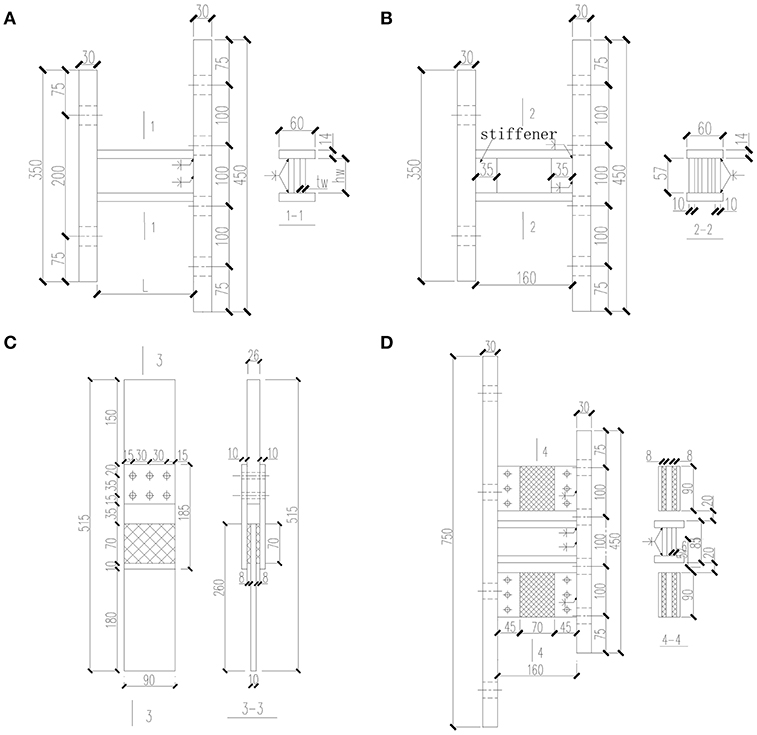
Figure 2. Test specimens: (A) metallic dampers M1–M7; (B) metallic damper M8; (C) VE damper; (D) combined damper.
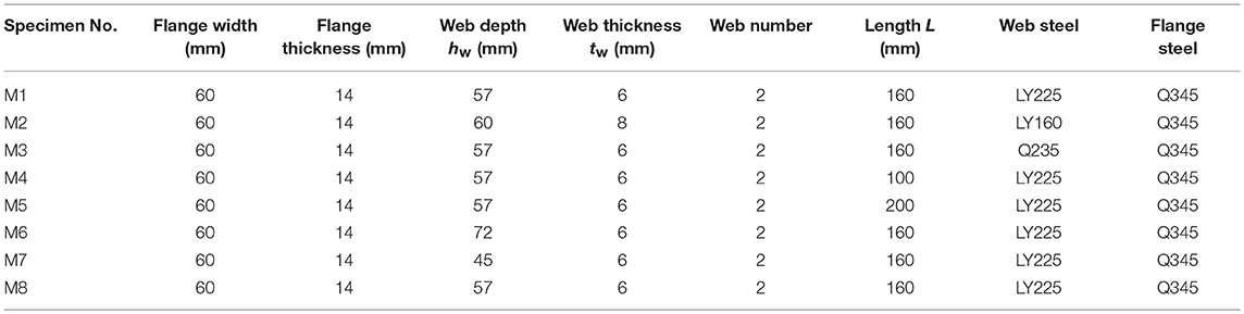
Table 1. Detailed parameters of metallic dampers.
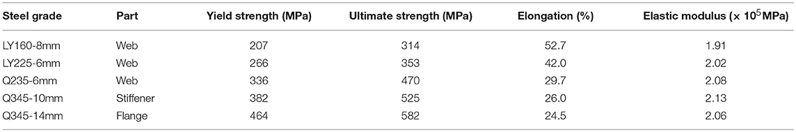
Table 2. Mechanical properties for steel of metallic dampers.
The VE damper consisted of two layers of 70 × 90 mm VE materials bonded between Q345 steel plates with a thickness of 10 mm. The VE material used in this study was an elastomeric one, which presented improved energy absorption capacity. For illustrative purpose, the two VE dampers were noted as V1 and V2, respectively. The thickness of the VE material for V1 was 6 and 8 mm for V2.
The combined damper was manufactured by placing two edge VE damper components and one central metallic damper component in parallel. Both ends of the three components were welded together to the 30 mm thick end plates.
Test Setup
The VE dampers were tested in a MTS uniaxial testing system (Figure 3A). The cyclic axial force was applied to the central VE damper through the specially designed connections. Figure 3B shows the setup for both the metallic damper and the combined damper. The test setup is a portal frame with four pins at each corner, with the tested dampers installed between the top loading beam and bottom foundation beam by high-strength bolts. Lateral load from the actuator is applied to the top loading beam.
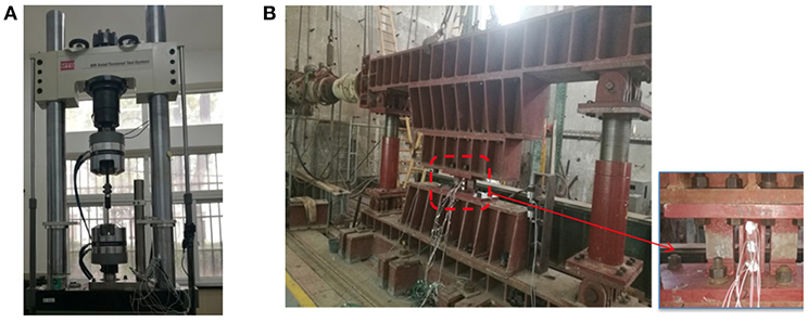
Figure 3. Test setup: (A) VE damper; (B) metallic damper and combined damper.
Loading Protocol
For the metallic dampers and the combined damper, the lateral load was applied by displacement control with each amplitude repeated three times according to Chinese specification of testing methods for earthquake resistant building (Ministry of Construction of China, 1997). The amplitude increment was 1% rotation, defined as the ratio of lateral displacement divided by the specimen height.
The displacement controlled loading was also applied to the VE dampers. Different from the loading protocol adopted for the above dampers, the displacement in the form of sinusoidal wave was used and five cycles were repeated for each amplitude. Also, to study the effect of loading frequency on its mechanical behavior, different loading frequencies were used for certain amplitudes. Table 3 gives the detailed loading protocol adopted. For Specimen V1, 12 loading frequencies are used at the amplitudes of 50 and 100%, and the constant frequency of 0.1 Hz is used for other amplitudes. For Specimen V2, to save the loading time, only 6 loading frequencies are used at the amplitude of 100%, and the constant frequency of 0.1 Hz is used for other amplitudes.
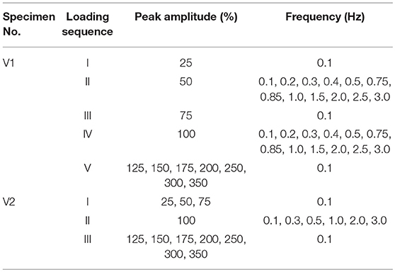
Table 3. Loading protocol of VE dampers.
The loading protocol of the combined damper basically followed that of the VE damper. The loading frequency was kept constant, i.e., 0.1 Hz, for all the amplitudes.
Test Results and Discussions
Metallic Dampers
Failure Mode
No web or flange buckling or local instability was observed during the test, indicating that the method to avoid web buckling by adopting small depth-thickness ratio was effective. The maximum depth-thickness ratio of 12 can be used as the threshold value in designing the web. Overall, the fracture occurred in the following positions as shown in Figure 4: (1) flange-to-end plate weld; (2) corners of the web next to the welds; and (3) web-to-flange weld.
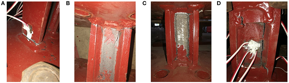
Figure 4. Damage pattern of fractures: (A) flange-to-end plate weld; (B) web corners next to the welds; (C) web-to-flange weld; (D) Specimen M8.
For Specimens M1 and M6, the fracture occurred at the flange-to-end plate weld and the corners of the web next to the welds. Cracks were first observed in the flange next to the steel plate weld. These cracks did not immediately propagate and enlarge. And the resistance did not decrease obviously until the corner of the web next to the welds fractured.
The flange-to-end plate weld fracture caused the failure of Specimens M2 and M5. No web damage was observed during the test. The main reason is that the web of Specimen M2 was made of LY160 steel whose ductility was better than that of LY225 steel and Q235 steel. As for Specimen M5, its length of 200 mm was the largest among all the specimens, which was more dominated by flexual behavior. The more obvious effect of diagonal tension at large shear deformation gave the higher stress level at the flange-to-end plate welds. Specimens M3, M4, and M7 had a similar damage development process. Cracks were first observed in the flange-steel plate weld, followed by the web-to-flange weld fracture. In the end, the development of the web-to-flange weld fracture caused the failure.
The flange-to-end plate weld fracture was not observed in Specimen M8. As previously stated, end plate stiffeners were used in Specimen M8. With the aid of stiffeners, the stress level at the flange-to-end plate weld was largely reduced, which shifted large plasticity position toward the middle part of the damper. The effectiveness of the stiffeners in preventing the flange-to-end plate weld fracture was demonstrated. With the increases of lateral displacement, fracture occurred in the stiffener-flange welds first. Finally, the web-to-flange weld was totally torn, causing the failure of Specimen M8. The failure mode is illustrated in Figure 4D.
Shear Force-Shear Rotation Relationship
Figure 5 shows the hysteretic curves, with abscissa being shear rotation defined as the ratio between the lateral displacement and the specimen height. The metallic dampers show very stable hysteretic loops and exhibit excellent deformation and energy-dissipation capability. With the increase of lateral displacement, the shear strength hardening is apparent, and there is no decline in bearing capacity until failure.
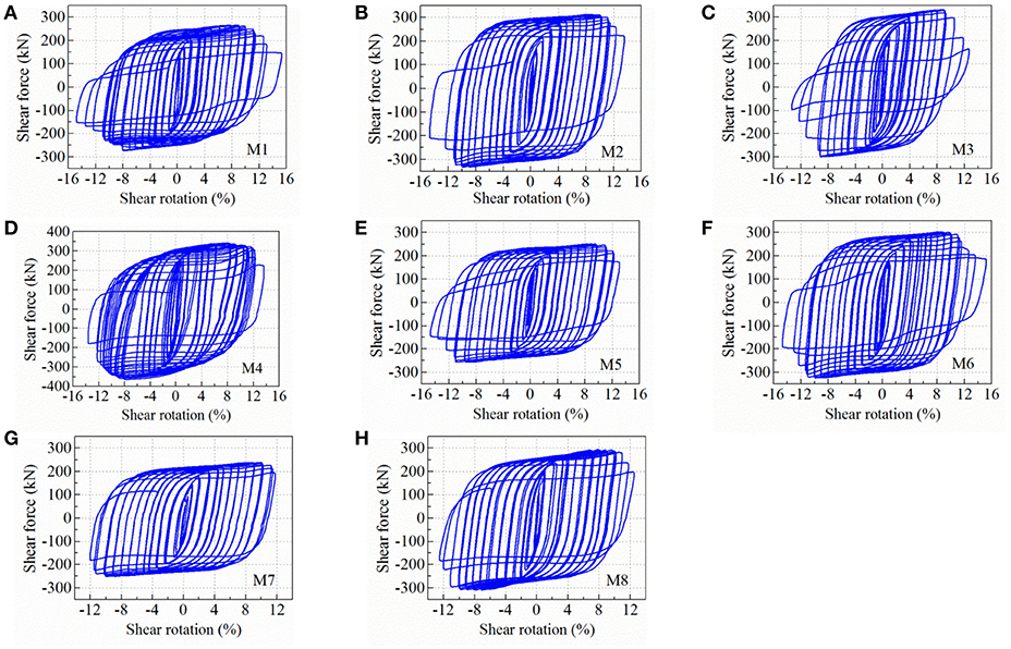
Figure 5. Hysteretic curves of metallic dampers: (A) M1; (B) M2; (C) M3; (D) M4; (E) M5; (F) M6; (G) M7; (H) M8.
The normalized shear force-shear rotation envelope curves are illustrated in Figure 6. The ordinate of shear force is normalized by the yield shear strength (Vy), which is calculated as 0.6 f yAw, where f y is the actual measured yield stress of the steel obtained from tensile coupon test, and Aw is the web sectional area. Table 4 summarizes the shear strength and deformation capacity of metallic dampers. The overstrength ratio (Vmax/Vy, with Vmax being the maximum shear force obtained in the test) is an important parameter to design the non-replaceable part of the coupling beam. Test results in this study found that the overstrength ratio increased with the decrease of length and height of web and yield stress of web steel. The overstrength ratio ranged from 2.27 to 3.24, and the average of overstrength ratio was 2.62. Specimen M2 made of LY160 demonstrated the largest ductility and shear strength. The only difference among Specimens M1, M4, and M5 was the specimen length. The shortest M4 exhibited the largest shear strength. Among Specimens M1, M6, and M7, M7 had the smallest web depth and exhibited the largest shear strength. Compared with the reference Specimen M1, Specimen M8 with end plate stiffener presented higher shear strength.
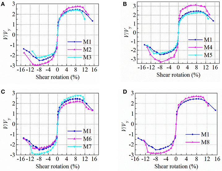
Figure 6. Normalized shear force-shear rotation envelope curves: (A) different web steel; (B) different specimen length; (C) different web depth; (D) different detailing.
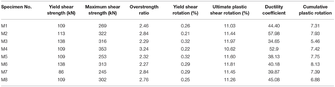
Table 4. Shear strength and deformation capacity of metallic dampers.
The ductility coefficient, defined as the ratio between the ultimate shear rotation and the yield shear rotation, is listed in Table 4. Compared with Specimen M3 (Q235 steel), the ductility coefficient of Specimens M1 (LY225 steel) and M2 (LY160 steel) increases by 28.1 and 67.3%, respectively. With the adoption of low-yield-point steel in the web, the ductility of the metallic damper is significantly enhanced. While the length and depth of the damper and the end stiffener have limited effect on the ductility. Table 4 also lists the ultimate plastic shear rotation and cumulative plastic rotation. The average ultimate plastic shear rotation is 0.11, which is larger than the value of 0.08 specified in the provisions of the AISC 341-10 (ANSI/AISC, 2010). The effect of web steel grade on the deformation capacity, such as the ultimate plastic shear rotation and cumulative plastic rotation, is remarkable. The ultimate plastic shear rotation and cumulative plastic rotation increase with decrease of yield stress of the web steel. Basically, the effect of length and depth of the damper on the ultimate plastic shear rotation and cumulative plastic rotation is slight.
Energy Dissipation Capacity
The energy dissipation capacity was generally evaluated by using equivalent viscous damping coefficient Ceq, which is calculated according to the following formula:
where Ehyst is the sum of the area enclosed by hysteretic loops, and Emax is energy absorbed by equivalent elastomers at the same displacement amplitude.
Figure 7 illustrates the calculated equivalent viscous damping coefficients of metallic dampers, using the first cycle at each shear rotation amplitude. The equivalent viscous damping coefficient rises as the shear rotation increases before the metallic damper damaged. The equivalent viscous damping coefficients are >0.5 for all specimens at the rotation beyond 0.03. For specimens with different web steel grade, the equivalent viscous damping coefficient increases as the web steel yield stress decreases (Figure 7A). With the decrease of length of web, the equivalent viscous damping coefficient increases slightly (Figure 7B). The height of the web has little effect on energy dissipation capacity (Figure 7C). With or without the end plate stiffener, the equivalent viscous damping coefficient is similar (Figure 7D).
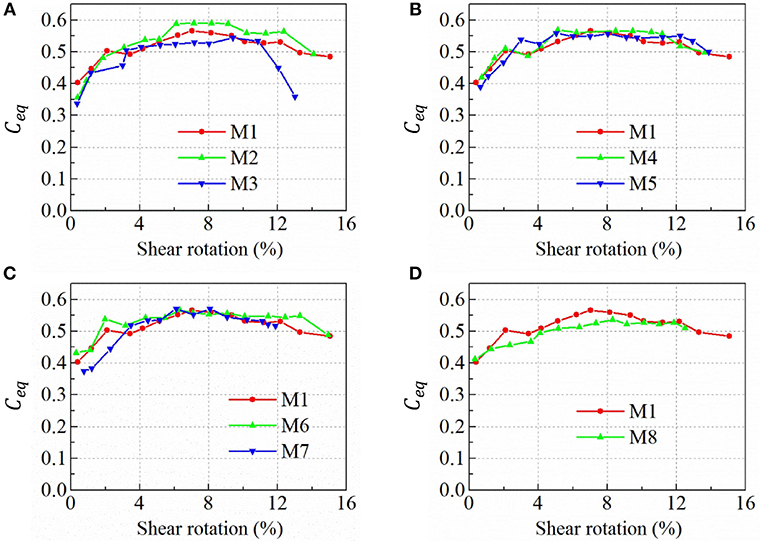
Figure 7. Equivalent viscous damping coefficients of metallic dampers: (A) different web steel; (B) different specimen length; (C) different web depth; (D) different detailing.
VE Dampers
Failure Mode
There was no separation observed between the VE layer and steel plate until 300% strain for both Specimens V1 and V2. When the strain amplitude reached 350%, the VE layer separated from the steel plate and the bearing capacity dropped subsequently.
Energy Dissipation and Strain Dependency
Figure 8 shows the hysteretic loops of Specimens V1 and V2 under various strains subject to a constant frequency 0.1 Hz. It can be seen that the VE damper dissipates energy at all strain ranges. In addition, hardening behavior under relatively large strain is clearly observed for both specimens. The shear storage modulus (G′), shear loss modulus (G″) and loss factor (η) are the most important factors reflecting the properties of VE damper. These factors can be obtained from the hysteresis curves, and can be expressed as:
where A is the VE material area, h is the thickness of the VE material, n is the layers of VE material, μ0 is the maximum displacement, F1 is the corresponding force at displacement μ0, and F2 is the corresponding force at zero displacement.
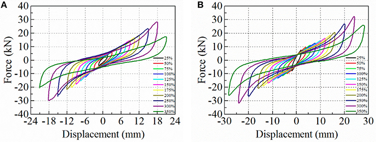
Figure 8. Hysteretic curves of VE dampers: (A) V1; (B) V2.
The variation of these factors with strain levels for two specimens are shown in Figure 9. Because of the thicker VE material layer, both the shear storage modulus and shear loss modulus of Specimen V2 are larger than that of Specimen V1. While the loss factor is quite similar for both specimens. In addition, the shear storage modulus, shear loss modulus and loss factor decrease with increase of strain. Beyond the strain of 250%, the storage shear modulus stops to decrease as hardening starts.
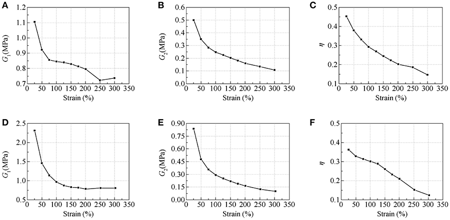
Figure 9. Strain dependency: (A) shear storage modulus of V1; (B) shear loss modulus of V1; (C) loss factor of V1; (D) shear storage modulus of V2; (E) shear loss modulus of V2; (F) loss factor of V2.
Frequency Dependency
As previously described, different loading frequencies were adopted for Specimen V1 at strain amplitudes of 50% and 100% and Specimen V2 at a strain amplitude of 100%. Figure 10 illustrates the variation of the shear storage modulus, shear loss modulus, and loss factor under different frequency. It can be seen that both the shear storage modulus and shear loss modulus decrease slightly as the excitation frequency increases within the frequency range between 0.1 and 1 Hz. However, the dependency on frequency is not obvious when the frequency exceeds 1 Hz. With the increase of strain amplitude, both the shear storage modulus and shear loss modulus decrease (Specimen V1). The loss factor is not significantly dependent on both of the shear strain amplitude and the frequency.
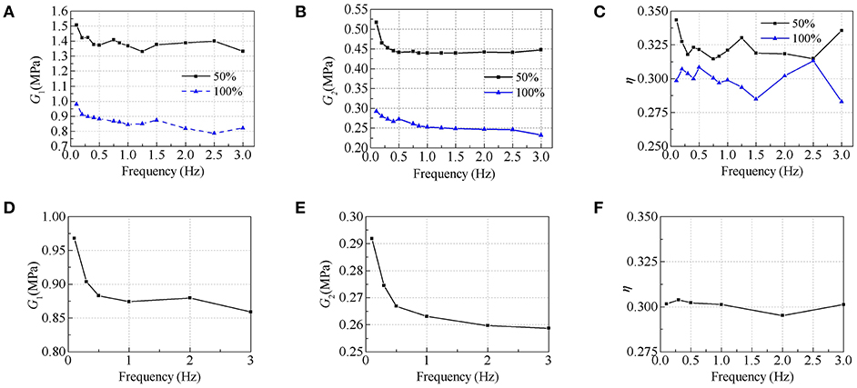
Figure 10. Frequency dependency: (A) shear storage modulus of V1; (B) shear loss modulus of V1; (C) loss factor of V1; (D) shear storage modulus of V2; (E) shear loss modulus of V2; (F) loss factor of V2.
Combined Damper
Failure Mode
The combined damper had the failure mode similar to Specimen M1. Cracks were first observed in the flange next to the steel plate weld when the rotation was 8.93%, and the bearing capacity continued to increase. The maximum shear strength reached 314 kN at the rotation of 9.92%. During the following loading cycles, cracks were observed at the coner of the web. Ultimately, the cracks tore through the entire length of the web along the flange welds, and the bearing capacity decreased. No damage of the VE damper was observed till the shear rotation of 12% when the equivalent strain of the VE material reached 240%.
Lateral Force-Displacement Relationship
Figure 11A shows the shear force vs. rotation hysteretic curves of the combined damper. With the increase of the displacement, the strength hardening is apparent. The hysteretic loop becomes S-shaped after the shear rotation of 12% because the hysteresis curve of the VE damper is S-shaped and the hardening is apparent when the strain of the VE material is >200%. The comparison of envelope curve between Specimen M1 and the combined damper is shown in Figure 11B. The strength and the stiffness of the combined damper are higher than that of metallic damper due to the contribution of VE damper. In comparison with the metallic damper, the initial stiffness of combined damper increases from 259 to 270 kN/mm, and the maximum shear strength increases from 269 to 314 kN. The VE damper contributes about 14% on the bearing capacity and 4% on the stiffness.
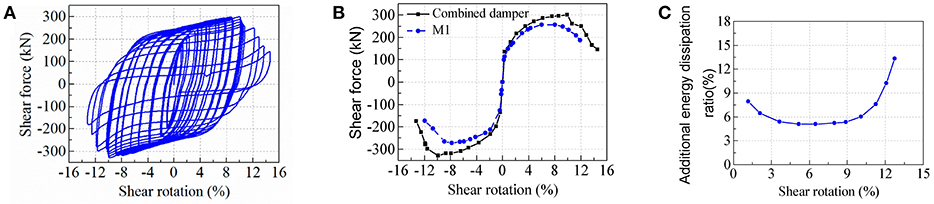
Figure 11. Combined damper: (A) hysteretic curve; (B) skeleton comparison with the metallic damper M1; (C) energy dissipation by VE damper.
Energy Dissipation
It can be seen from Figure 11B that, basically, the combined damper experiences a greater force at the same deformation, indicating that the combined damper dissipates more energy than metallic damper. Figure 11C shows the ratio of the energy dissipated by the VE damper to that of the total energy in the combined damper. As indicated in the figure, the additional energy dissipation ratio is 8% at small deformation level, and then drops to 5.5% as the energy dissipated by metallic damper increases. After the metallic damper fails, the ratio increases significantly.
Estimation of Elastic Stiffness and Yield Strength
The stiffness of the metallic damper (KM) and VE damper (KV) can be expressed respectively as follows:
where L is the length of the metallic damper, μ is the correction coefficients, A and Av are, respectively the web cross sectional area of metallic damper and the shear area of the VE damper, I is the cross sectional moment of inertia of metallic damper, E and G are respectively the elastic modulus and shear modulus of metallic damper, and G′ is shear storage modulus of the VE material.
The elastic stiffness of the combined damper is then the summation of metallic damper and VE damper:
As previously mentioned, the yield shear strength (Vy) of the metallic damper was calculated as:
where f y is the yield strength of the steel, and Aw is the web sectional area.
As shown in Figure 6, the ordinate of ±1 gives the inflection point in the shear force-rotation envelope curve, which indicates that Equation (8) is capable of capturing the yield shear strength of the metallic dampers. As there is no clear yield point in the hysteresis of the VE damper, its yield shear strength can be conservatively estimated as the shear strength at the moment when the metallic damper yields. The yield shear strength of the combined damper can be calculated as:
where Δy is the yield displacement of metallic damper, determined as the ratio between the yield shear strength derived by Equation (8) and the stiffness derived by Equation (5).
According to Equation (7), the predicted elastic stiffness of the combined damper is 280 kN/mm with an error of 3.7% compared with the test result of 270 kN/mm. Equation (9) gives the yield shear strength of 112 kN, with an error of 7.4% compared with the test result of 122 kN. Basically, the analytical solutions predicts well both the elastic stiffness and yield shear strength.
Conclusions
A new damper, combining the viscoelastic damper and metallic damper used for replaceable coupling beams, is proposed and studied in this paper. Through a series of experimental study, the major findings are summarized as follows:
(1) No web instability was observed, indicating that unstiffened webs with depth-thickness ratio < 12 was sufficient to avoid web buckling. The web end stiffeners effectively reduced the flange stress at the ends of the specimen, which prevented the failure of flange-to-end plate welds.
(2) The maximum overstrength ratio of the metallic damper reached 3.24 with an average of 2.62. The overstrength ratio increased with the decrease of the length or depth of web or the yield strength of web steel.
(3) The effect of web steel grade on the deformation and energy dissipation capacity of the metallic damper was remarkable. The metallic damper using low-yield-point steel exhibited excellent ductility and energy dissipation capacity. While the length and depth of the damper and the installation of end stiffener had limited effect.
(4) No damage occurred at the shear surface between the VE layer and steel plate until the strain of 300%, and the VE layer and steel plate started to separate at the strain of 350%.
(5) The shear storage modulus, shear loss modulus, and loss factor of the VE material decreased with the increase of strain. Both the shear storage modulus and shear loss modulus decreased slightly with the increase of loading frequency ranging from 0.1 to 1 Hz. However, the dependency on frequency was not obvious when the frequency exceeded 1 Hz. The loss factor was not significantly dependent on the loading frequency.
(6) The combined damper illustrated stable hysteretic loops and exhibited excellent deformation capability. The predicted elastic stiffness and yield shear strength agreed well with test results.
Author Contributions
HJ supervised the research and revised the manuscript. SL conducted the experiments, analyzed data and wrote manuscript partially. LH reviewed and revised the manuscript. All the authors participated in discussion of the research.
Funding
The authors are grateful for the support from National Key Research and Development Program of China under Grant No. 2017YFC1500701 and Program of Shanghai Academic Research Leader under Grant No. 18XD1403900.
Conflict of Interest Statement
The authors declare that the research was conducted in the absence of any commercial or financial relationships that could be construed as a potential conflict of interest.
References
ANSI/AISC (2010). AISC 341-10, Seismic Provisions for Structural Steel Buildings. Chicago, IL: American Institute of Steel Construction.
Chung, H. S., Moon, B. W., Lee, S. K., Park, J. H., and Min, K. W. (2009). Seismic performance of friction dampers using flexure of Rc shear wall system. Struct. Des. Tall Spec. 18, 807–822. doi: 10.1002/tal.524
Dusicka, P., Itani, A. M., and Buckle, I. G. (2009). Cyclic behavior of shear links of various grades of plate steel. J. Struct. Eng. 136, 370–378. doi: 10.1061/(ASCE)ST.1943-541X.0000131
Fortney, P. J., Shahrooz, B. M., and Rassati, G. A. (2007). Large-scale testing of a replaceable “Fuse” steel coupling beam. J. Struct. Eng. 133, 1801–1807. doi: 10.1061/(ASCE)0733-9445(2007)133:12(1801)
He, L., Togo, T., Hayashi, K., Kurata, M., and Nakashima, M. (2016). Cyclic behavior of multirow slit shear walls made from low-yield-point steel. J. Struct. Eng. 142:04016094. doi: 10.1061/(ASCE)ST.1943-541X.0001569
Hitaka, T., and Matsui, C. (2003). Experimental study on steel shear wall with slits. J. Struct. Eng. 129, 586–595. doi: 10.1061/(ASCE)0733-9445(2003)129:5(586)
Ji, X. D., Wang, Y. D., Ma, Q. F., and Okazaki, T. (2016). Cyclic behavior of very short steel shear links. J. Struct. Eng. 142:04015114. doi: 10.1061/(ASCE)ST.1943-541X.0001375
Jiang, H., Li, S., and Zhu, Y. (2017). Seismic performance of high-rise buildings with energy-dissipation outriggers. J. Construct. Steel Res. 134, 80–91. doi: 10.1016/j.jcsr.2017.03.013
Kam, W. Y., and Pampanin, S. (2011). The seismic performance of RC buildings in the 22 February 2011 christchurch earthquake. Struct. Concrete 12, 223–233. doi: 10.1002/suco.201100044
Kurata, M., He, L., and Nakashima, M. (2015). Steel slit shear walls with double-tapered links capable of condition assessment. Earthq. Eng. Struct. Dyn. 44, 1271–1287. doi: 10.1002/eqe.2517
Lu, X., Chen, C., Jiang, H., and Wang, S. (2018a). Shaking table tests and numerical analyses of an RC coupled wall structure with replaceable coupling beams. Earthq. Eng. Struct. Dyn. 47, 1882–1904. doi: 10.1002/eqe.3046
Lu, X., Chen, Y., and Jiang, H. (2018b). Earthquake resilience of reinforced concrete structural walls with replaceable “Fuses”. J. Earthq. Eng. 22, 801–825. doi: 10.1080/13632469.2016.1264330
Lu, Z., Huang, B., Zhang, Q., and Lu, X. (2018a). Experimental and analytical study on vibration control effects of eddy-current tuned mass dampers under seismic excitations. J. Sound Vibr. 421, 153–165. doi: 10.1016/j.jsv.2017.10.035
Lu, Z., Huang, B., and Zhou, Y. (2018b). Theoretical study and experimental validation on the energy dissipation mechanism of particle dampers. Struct Control Health Monit 25:e2125. doi: 10.1002/stc.2125
Mackay-Lyons, R., Christopoulos, C., and Montgomery, M. (2012). “Enhancing the seismic performance of RC coupled wall high-rise buildings with viscoelastic coupling dampers,” in Proceedings of the 15th World Conference on Earthquake Engineering (Lisboa).
Ministry of Construction of China (1997). Specification of Testing Methods for Earthquake Resistant Building JGJ 101-96, Beijing: China Architecture and Building Press (in Chinese).
Montgomery, M., and Christopoulos, C. (2015). Experimental validation of viscoelastic coupling dampers for enhanced dynamic performance of high-rise buildings. J. Struct. Eng. 141:04014145. doi: 10.1061/(ASCE)ST.1943-541X.0001092
Okazaki, T., and Engelhardt, M. D. (2007). Cyclic loading behavior of EBF links constructed of ASTM A992 steel. J. Constr. Steel Res. 63, 751–765. doi: 10.1016/j.jcsr.2006.08.004
Shi, Q.-X., Wang, F., Wang, P., and Chen, K. (2018). Experimental and numerical study of the seismic performance of an all-steel assembled Q195 low-yield buckling-restrained brace. Eng. Struct. 176, 481–499. doi: 10.1016/j.engstruct.2018.09.039
Takeuchi, T., Hajjar, J., Matsui, R., Nishimoto, K., and Aiken, I. (2012). Effect of local buckling core plate restraint in buckling restrained braces. Eng. Struct. 44, 304–311. doi: 10.1016/j.engstruct.2012.05.026
Tsai, K.-C., Chen, H.-W., Hong, C.-P., and Su, Y.-F. (1993). Design of steel triangular plate energy absorbers for seismic-resistant construction. Earthq. Spectra 9, 505–528. doi: 10.1193/1.1585727
Wallace, J. W. (2012). Behavior, design, and modeling of structural walls and coupling beams - Lessons from recent laboratory tests and earthquakes. Int. J. Concr. Struct. Mater. 6, 3–18. doi: 10.1007/s40069-012-0001-4
Wang, B., and Zhu, S. (2017). Seismic behavior of self-centering reinforced concrete wall enabled by superelastic shape memory alloy bars. Bull. Earthq. Eng. 16, 479–502. doi: 10.1007/s10518-017-0213-8
Wang, T., Guo, X., He, X., Duan, C., and Du, Y. (2012). Experimental study on replaceable hybrid coupling beams. Appl. Mech. Mater. 166–169, 1779–1784. doi: 10.4028/www.scientific.net/AMM.166-169.1779
Xu, Z., Guo, Y., and Wang, S. (2013a). Xing-Huai Huang. Optimization analysis on parameters of multi-dimensional earthquake isolation and mitigation device based on genetic algorithm. Nonlin. Dyn. 72, 757–765. doi: 10.1007/s11071-013-0751-9
Xu, Z., Huang, X., Xu, F., and Yuan, J. (2019). Parameters optimization of vibration isolation and mitigation system for precision platforms using non-dominated sorting genetic algorithm. Mech. Sys. Signal Process. 128, 191–201. doi: 10.1016/j.ymssp.2019.03.031
Xu, Z., Liao, Y., Ge, T., and Xu, C. (2016). Experimental and theoretical study on viscoelastic dampers with different matrix rubbers. J. Eng. Mech. ASCE 142:04016051. doi: 10.1061/(ASCE)EM.1943-7889.0001101
Xu, Z., Sha, L., and Zhang, X. (2013b). Design, performance test and analysis on magnetorheological damper for earthquake mitigation. Struct. Control Health Monit. 20, 956–970. doi: 10.1002/stc.1509
Xu, Z., Shen, Y., and Zhao, H. (2003). A synthetic optimization analysis method on structures with viscoelastic dampers. Soil Dyn. Earthq. Eng. 23, 683–689. doi: 10.1016/j.soildyn.2003.07.003
Keywords: coupling beam, replaceable, metallic damper, viscoelastic damper, combined damper
Citation: Jiang H, Li S and He L (2019) Experimental Study on a New Damper Using Combinations of Viscoelastic Material and Low-Yield-Point Steel Plates. Front. Mater. 6:100. doi: 10.3389/fmats.2019.00100
Received: 14 January 2019; Accepted: 17 April 2019;
Published: 03 May 2019.
Edited by:
Zhao-Dong Xu, Southeast University, ChinaReviewed by:
Wei Wang, Xi'an University of Architecture and Technology, ChinaYongfeng Du, Lanzhou University of Technology, China
Copyright © 2019 Jiang, Li and He. This is an open-access article distributed under the terms of the Creative Commons Attribution License (CC BY). The use, distribution or reproduction in other forums is permitted, provided the original author(s) and the copyright owner(s) are credited and that the original publication in this journal is cited, in accordance with accepted academic practice. No use, distribution or reproduction is permitted which does not comply with these terms.
*Correspondence: Liusheng He, aGxzQHRvbmdqaS5lZHUuY24=