 Jianwei Tu
 Zhao Li
 Jiarui Zhang
- Hubei Key Laboratory of Roadway Bridge & Structure Engineering, Wuhan University of Technology, Wuhan, China
As a semi-active control device, the magnetorheological (MR) damper has received much praise for its great controllability, quick response, and lower input power. However, the problem of liquid leakage arises after its long-term service, severely affecting its performance and service life. To solve this problem, this paper proposes fully vulcanizing and consolidating viscoelastic material, the cylinder barrel and the piston rod, which replaces the traditional dynamic seal with a static seal, and developing a new leak-proof MR damper. Considering that viscoelastic material has a certain energy dissipation and fluid-structure interaction with MR fluid, the correction factor of the pressure gradient is introduced to establish the mechanical model of the leak-proof MR damper which is to be tested. The testing result shows that warpage deformation of viscoelastic material weakens the damping force of the MR damper and the weakening effect increases with current intensity. Given the influence of current intensity on the correction factor, the complete mechanical model of the leak-proof MR damper is obtained on the basis of the verified model. Through the comparison between the theoretical calculation curve and the test curve, the revised mechanical model is found to well reflect the mechanical properties of the leak-proof MR damper.
Introduction
Magnetorheological (MR) Fluid is a solid/liquid two-phase suspension produced by magnetizable particles dispersing in the carrier fluid. It is a new smart fluid material whose mechanical properties are adjusted remarkably by the external magnetic field. In the external magnetic field, the random disorder state of magnetizable particles is transformed into an orderly chain along the external magnetic field direction, changing MR material from homogeneously dispersed solid/liquid two-phase suspension into solid-like material. This process is fast, reversible, and controllable (Hardy, 1951; Jacob, 1951; Carlson and Spencer, 1996). Researches indicate that MR fluid is typically characterized by the shear stress, and apparent viscosity changing with the external shear rate and magnetic field intensity, and that the type, saturation magnetization, surface characteristic, size, and morphology of magnetizable particles (Jolly et al., 1999; Hato et al., 2011; Susan-Resiga and Vékás, 2014; Liu et al., 2015; Vereda et al., 2016; Mohamad et al., 2018) have a great influence on the mechanical properties of the MR material. Due to the apparent sedimentation of MR fluid, MR grease has been proposed, improving its anti-sedimentation greatly (Zhu, 2006; Hu et al., 2015). At present, the most outstanding use of MR fluid (grease) is that it is placed into a sealed container with an adjusted magnetic field to make a smart shock absorber with an adjustable damping force (Xu et al., 2013; Deng et al., 2017; Zhang et al., 2017; Christie et al., 2019), which is applied in many areas such as vibration reduction, vibration isolation, vibration absorption, and protection (Xu et al., 2000; Qu et al., 2009). For instance, there are applications in vibration control of truck seats in the auto industry (Choi et al., 2000; Sun et al., 2016), vibration control to reduce low-frequency vibration and high-frequency shock vibration of vessels in navigation field (Yao et al., 2008), vibration control to reduce the ground shock vibration of airplane landing in aviation field (Zhu et al., 2011), vibration isolation and mitigation for the precision platform of precision instrument (Xu et al., 2019).
However, the problem of liquid leakage will take place after long-term service because most magnetorheological fluid (grease) dampers are sealed with rubber seal rings. When the damper piston is moving in a reciprocating motion, friction between magnetizable particles embedded in the rubber ring and the piston rod creates vertical nicks on the rod and the carrier fluid will leak from those nicks, causing the seal failure of the damper. Some research shows that with fluid leakage, its mechanical properties will change greatly, the energy consumption area will decrease sharply, and controlling time delay will be longer, which seriously affects the vibration control effect of the MR fluid (grease) damper (Iyengar et al., 2004; Lu et al., 2011; Wang et al., 2012; Tudón-Martínez and Morales-Menendez, 2015; Jeyasenthil and Choi, 2018). Therefore, leakage shortens the service life of the MR fluid (grease) damper and restricts its application in practical projects.
To solve the problem of its leakage, Carlson (1999) has used a porous sponge material in the MR fluid damper. Under suction of capillary tubes, MR fluid is stored in the pores of the porous sponge to reduce MR fluid leakage. Kelso et al. (2003) have designed a two-tiered seal device in the damper. The first tier is at the in-out position of the piston rod, and the second is between the piston and cylinder body. The two-tiered seal can effectively prevent the damper fluid leakage. Iyengar et al. (2004) carried out the seal wear test of rod seals in a MR damper to research the wear process of the rod when the damper was working. The best sealing material is determined by wear test of fluids on sealing materials. Xu and Cao (2004) installed MRF sealing device on the inner side of cylinder barrel. The magnetic field generated by the permanent magnet is used to make the MRF form a strong liquid film, which avoids the wear and liquid leakage of the MR damper. Giorgetti et al. (2010) have designed a rotary MR damper, remarkably decreasing MR fluid sedimentation and wear of the seal device, and improving the damper durability. Tu et al. (2011) have sprayed a hard alloy coat onto the damper piston rod to improve its rigidity and delay its nicking damage, which can effectively lengthen the damper service life. Yan et al. (2013) have stored MR material with porous metallic foams in the damper to make a porous metallic foam MR damper, which can effectively reduce its leakage without a sophisticated seal. Zhou et al. (2013) used metal sealing device instead of rubber sealing to overcome the leakage problem of damper caused by aging and corrosion of rubber sealing ring. Yazid et al. (2014) have proposed a new radial hydraulic seal device, which can effectively reduce the leakage at the sealing device. Sun et al. (2016) proposes to use a rotating MR damper in seat suspension to effectively solve the shortcomings of linear dampers. The rotating MR damper can reduce not only the amount of MRF needed but also the sealing requirements. Since the O-ring cannot completely prevent hydraulic oil leakage, Delgado and San Andres (2010) have employed an end seal device with a spring contact, which has been found in testing to reduce oil leakage and air ingestion.
Most researchers propose improving the original O-ring/piston seal, and optimizing and applying a multi-tiered sealing device. Those methods can delay the fluid leakage, lengthen the service life of the MR fluid (grease) damper, but they cannot completely solve its leakage problem mainly because the dynamic seal between the O-ring and the piston will inevitably create friction damage and cause leakage. This paper proposes a static seal for the MR fluid (grease) damper. The static seal adopts viscoelastic material as the sealing material, which can produce large elastic-plastic shear deformation to ensure that viscoelastic material moves with the piston and avoids being damaged in shear deformation. This material has two properties of energy dissipation and energy storage (Christensen and Freund, 1982). When suffering external forces, its strain obviously lags behind stress, whose straining motion works over a great resistance. Some of the energy is consumed by conversion into heat and some is stored in the form of potential energy, which has a good energy dissipation action (Samali and Kwok, 1995). Viscoelastic material is extensively applied in the ship industry (Townsend et al., 2018), space industry (Cunha-Filho et al., 2016), civil engineering (Tezcan and Uluca, 2003; Xu et al., 2016) etc. Viscoelastic material is selected to be the sealing material for the leakage-proof MR damper. It is connected between the damper cylinder barrel and the piston through microwave vulcanization so that relative motion and friction will not occur between the sealing material and the piston rod in its reciprocating motion. A relative displacement is created between the piston rod and the cylinder barrel by the material's own shear deformation, forming a static seal and the viscoelastic material can absorb energy to improve the damper through its own deformation. According to this principle, a new leakage-proof MR damper is developed to radically resolve the problem of MR fluid (grease) leakage from the damper.
After applying a viscoelastic material and making the static seal device, the mechanical model of the new leakage-proof MR damper has been changed significantly and must describe the dynamic properties of both viscoelastic material and MR material. In studying the mechanical model of MR material, Stanway et al. (1987) have treated MR fluid as yield stress material and suggested the Bingham model concerning the linear relationship between shear stress and shear rate of MR fluid. Based on Bingham model, Çeşmeci and Engin (2010) have performed experiments on the linear MR fluid damper, which can predict well the outputting force of the MR fluid damper. Yang (2001) have proposed the Herschel-Bulkley model to describe the shear-thinning behaviors of MR fluid while Wen (1976) has suggested the Bouc-Wen model which is universal and is able to calculate and reflect various hysteresis curves. In studying the mechanical model of viscoelastic material, Chang et al. (1993) have suggested the Kelvin model which is formed by parallel connection of the linear spring and linear damper unit, reflecting creep and relaxation of viscoelastic material. Zhang and Soong (1992) have proposed the Maxwell model, which is formed by a series connection of the linear spring and linear damper unit. Liu (1990) has suggested the standard linear solid model, which is formed by a series connection of the spring unit and Kelvin model, reflecting both creep and relaxation of viscoelastic material and its property changes with frequency. On the basis of a standard linear solid model, Xu et al. (2010) have proposed the equivalent standard solid model with temperature-frequency equivalent theory which can accurately reflect its property changes with temperature and frequency. This paper establishes the mechanical model of a new leakage-proof MR fluid damper and tests it through the damper performance tests.
From the above research, a leakage-proof MR damper is developed to solve the leakage problem of MR damper. The leakage-proof MR damper uses viscoelastic material to vulcanize both the cylinder and piston rod, which replaces the traditional dynamic seal with a static seal. However, considering the energy-consumption of viscoelastic material and the fluid-structure interaction between viscoelastic material and magnetorheological fluid, the mechanical model of leakage-proof MR damper is changed. Based on the traditional MR damper mechanical model, the correction factor of a pressure gradient is introduced to consider the influence of viscoelastic materials on leak-proof dampers and establish the mechanical model of the leak-proof MR damper. In addition, the mechanical properties of the new MR damper also tested. It can be found that the new MR damper has good sealing performance and can fundamentally solve the leakage problem of MR damper. The mechanical model of leakage-proof MR damper can well reflect its mechanical properties.
The Sealing Structure of the New Leakage-Proof MR Damper
When the MR damper works, its chamber is filled with MR fluid in a high-pressure condition. To prevent leakage, an O-ring made of rubber is usually devised at the port to seal the damper, as is shown in Figure 1. The O-ring, a regular sealing element of fluid damper, is characterized by easy manufacture, simple structure, and low cost.
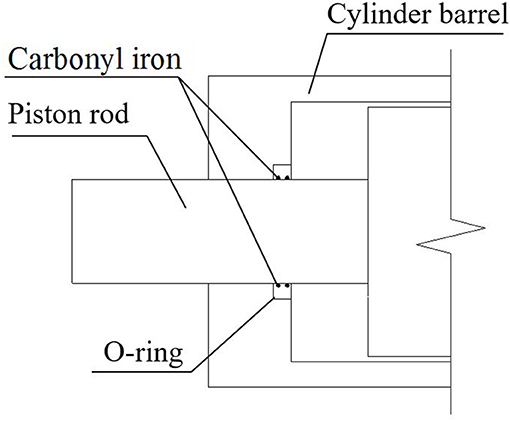
Figure 1. The sealing device of a regular MR damper.
As for a MR damper, magnetizable particles are embedded into the rubber O-ring by the great pressure inside the chamber, and then produce dry friction with the piston rod at the fixed position on the sealing ring. Due to the great rigidity of those particles, vertical nicks are created on the rod when it moves many times. MR fluid in the damper will leak from those nicks, seriously influencing its performance and service life. In order to solve the leakage problem of the traditional MR damper, a new leakage-proof MR damper is designed in Figure 2. Viscoelastic material is inserted between the cylinder barrel and the piston rod. And cylinder barrel, viscoelastic material and the piston rod are entirely connected through microwave vulcanization. The connection strength can reach the failure strength of viscoelastic materials.
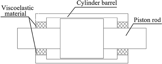
Figure 2. The new leakage-proof MR damper.
When the damper operates, the reciprocating motion of the piston will cause viscoelastic material to move along, using the material's own shear deformation to make up for the displacement difference between the external cylinder barrel and the piston, as shown in Figure 3. In this case, no friction exists between the viscoelastic material and the piston rod, which replaces the dynamic seal with a static seal successfully. Magnetizable particles are unlikely to be embedded into the viscoelastic material to produce friction damage to the piston rod, so that the leakage problem of the traditional MR damper is radically resolved, as is shown in Figure 4. Besides, viscoelastic material has a stable chemical performance and strong corrosion and fatigue resistance, lengthening the damper service life and improving its engineering applicability, as shown in Figure 5. In the new sealing device, thickness and coherent length of viscoelastic material need designing according to reality, and a new mechanical model needs establishing to describe the mechanical properties because many changes happen to the damper.
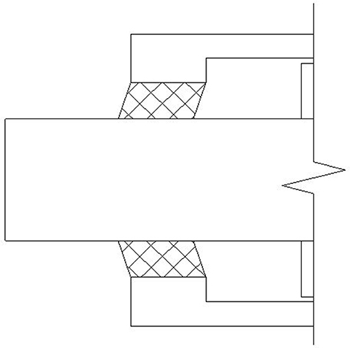
Figure 3. Shear deformation of viscoelastic material.
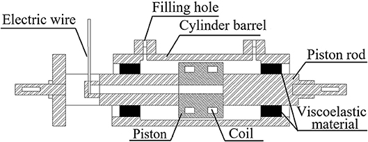
Figure 4. The section diagram of the leakage-proof MR damper.
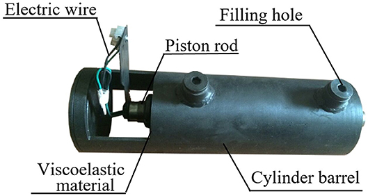
Figure 5. The real diagram of the leakage-proof MR damper.
The Mechanical Model of the New Leakage-Proof Mr Damper
With viscoelastic material, the new leakage-proof MR damper is changed, compared with the traditional one in the following manner: (1) viscoelastic material itself is an energy-consume damping material. Serving as a sealing device, it will change the damping and stiffness of the device; (2) fluid-structure interaction will occur between viscoelastic material and MR fluid. On the one hand, when the MR damper works, the high pressure created by internal fluid produces warpage deformation of the viscoelastic material; on the other hand, its warpage deformation will influence the internal pressure of the damper in return. Those changes alter the damping force of the new leakage-proof MR damper. A new mechanical model must be established.
The Inner Chamber Volume Increment Caused by Warpage Deformation of Viscoelastic Material
The fluid pressure of the inner chamber produces warpage deformation of the viscoelastic material, as shown in Figure 6, which results in larger inner chamber capacity, smaller inner chamber pressure, and then less fluid flow through the gap channel of the damper. Fluid flow QΔV can be obtained as:
in which V is the fluid volume through the gap channel, ΔV is the inner chamber volume increment caused by viscoelastic material deformation, and Q0 is the fluid flow through the gap channel without considering viscoelastic material deformation.
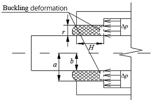
Figure 6. Deformation computing model of viscoelastic material.
The relationship between viscoelastic material deformation ΔV and the inner chamber fluid pressure Δp is obtained by the first-order shear deformation plate theory (Wang and Ma, 2004). The dimensions of the new leakage-proof damper are shown in Figure 6.
Under the pressure, the corner close-form expression ψ and the deflection close-form ω of viscoelastic material can be obtained as:
in which Ω = EH3/12(1 − v2), and As = ksEH/2(1 + μ2); Δp is the pressure difference at the damper gap channel; r is the difference between inside and outside diameters of viscoelastic materials; E is the elastic modulus of viscoelastic material; H is the vulcanizing and coherent length of viscoelastic material and the piston; μ is the Poisson ratio of viscoelastic material; ks is the shear correction factor.
The boundary conditions of viscoelastic tier are: Ψa = Ψb = 0, ωa = ωb = 0. Four unknown numbers C1, C2, C3, C4 can be obtained and substituted into Formula (3) to obtain the deflection curve. Volume increment of viscoelastic material is obtained by integrating the deflection curve. Because the fluid pressure changes with time, the deformation volume of the viscoelastic material also changes with time:
in which a and b are the distance between the center line of the piston rod and the two bonding surface; ω(r, t) is the deflection curve of viscoelastic material.
The Correction Factor of Pressure Gradient
Because the ratio of the gap between the external cylinder barrel and the piston and the inner diameter of cylinder is very small, a parallel model (Yang, 2001) can be used to approximately simulate an axisymmetric fluid model. Figure 7 shows the velocity profile diagram of MR fluids through parallel plates. For the different regions in Figure 7, the fluid velocity formulas are as follows:
MR fluids in the core region “C” will flow as a whole, and the velocity of flow in the core region is ux(h1) = ux(h2).
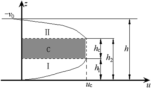
Figure 7. The velocity profile diagram of MR fluids through the gap.
From the above formulas, the fluid flow through the damper gap can be obtained:
in which Ap is the effective area of the piston; v0 is the speed of the piston; s is the circumference of the piston; ux(z) is the gap fluid velocity equation; η is the viscosity of MR fluid; dp/dx is the pressure gradient; h, h1, and h2 are shown in Figure 7.
The gap pressure gradient is expressed from (7):
From (1) and (8), warpage deformation of viscoelastic material will influence the gap flow of MR fluid, and then influence the gap pressure gradient, while the pressure gradient will directly change the damping force of the MR damper. To consider the influence of viscoelastic material deformation on the gap pressure gradient, the correction factor of pressure gradient α is obtained:
in which is the gap pressure gradient considering the influence of viscoelastic material deformation.
To most gap-type MR dampers, the ratio between h2 and h can be set to be 0.7 (Spencer et al., 1998).
In the movement of the damper piston, the gap pressure gradient changes at any moment, so that the correction factor of pressure gradient α also changes with time. Also, with the external current intensity increasing, the internal pressure of the damper increases, causing warpage deformation of the viscoelastic material to increase and influence the gap pressure gradient. Therefore, the correction factor of pressure gradient also considers the influence of current intensity.
The correction factor of pressure gradient of the MR damper is obtained by cycle computing of liquid-structure interaction. The computing process is: the initial pressure gradient Δp(t0) of the moment t0 = 0 is substituted into (2) and (3) to calculate the deflection curve ω(r, t0) of viscoelastic material, and then the deformation volume ΔV(t0) of viscoelastic material is obtained by integrating (4); the correction factor of pressure gradient at the next moment is obtained by (10); the pressure difference Δp(t1) with consideration of the viscoelastic material deformation influence at the next moment is obtained by (12); the correction factor of pressure gradient α changing with time is obtained by cycle computing.
According to the capacity formula of the MR damper gap, the modified damping force produced by MR fluid with considering viscoelastic material deformation influence is obtained:
in which FΔV is the MR damping force considering the viscoelastic material deformation influence; Fsv is the traditional MR damping force; L is the effective length of the piston.
When the damper works, its inner chamber pressure difference changes with time, and a fluid-structure interaction exists between viscoelastic material and the inner chamber MR fluid. The inner chamber fluid pressure difference produces deformation of viscoelastic material, leading to the increase of the damper inner chamber volume, and the decrease of the gap flow and pressure difference. The decrease of the pressure difference results in the decrease of viscoelastic material deformation and then of the damper inner chamber volume, and the increase of the gap flow and of the pressure difference. Thus, a time formula related to the correction factor of pressure gradient should be established to obtain the mechanical model of the damper at work.
The internal pressure difference of the damper mostly originates from the MR damping force. The formula for the pressure difference considering the viscoelastic material deformation influence is:
The Damping Force of the New Leakage-Proof MR Damper
The new leakage-proof MR damper is composed of two parts: one is provided by the pressure gradient created at the gap the MR fluid flows through, and the other is provided by elastic-plastic deformation of viscoelastic material. The damping force created by the pressure gradient is obtained:
The piecewise 3-order polynomial model with high fitting accuracy is used to calculate the damping force of traditional dampers.
in which, ad1, ad2, ad3, au1, au2, au3 are coefficients of piecewise polynomials respectively; v1,v3are the yielding velocities of the negative acceleration section; v2,v4 are the yielding velocities of the positive acceleration section; v1,v2,v3,v4 are the velocity values at the turning points of the two branch curves, and they are all functions of the current.
The damping force provided by viscoelastic material is:
According to the standard linear solid model (Xu et al., 2010), the formula of its modulus and dissipation factor is:
in which n is the number of viscoelastic material; G1 and G2 are storage modulus and consuming modulus respectively; u is the relative displacement of the piston; v0 is the velocity of the piston; A is the equivalent flat area of viscoelastic material; t is the thickness of material; η2 is the loss factor of viscoelastic material; λ is excitation frequency. The coefficients of q0, q1, and p1 are determined by the properties of viscoelastic materials.
Finally, the damping force of the leakage-proof MR damper is obtained:
The Performance Test of the New Leakage-Proof MR Damper
The Test Surveys
The parameters of self-made leakage-proof MR damper are shown in Table 1. A regular MR damper with an O-ring seal is also made, and its main parameters are the same as those of the leakage-proof MR damper, except with no viscoelastic material as the seal device. Performance tests are conducted on both dampers. There are three operating conditions: (1) the performance test for the leakage-proof MR damper without MR fluid, that is, only considering the outputting force of viscoelastic material; (2) the performance test for the regular MR damper; (3) the performance test for the leakage-proof MR damper with MR fluid, as shown in Tables 2–4. The fatigue performance test was conducted for both dampers. The hydraulic servo system is used to perform the loading test to the damper, as shown in Figure 8 and the test data for force and displacement are obtained through data acquisition system to draw the corresponding hysteresis curve.

Table 1. The main parameters of the leakage-proof MR damper.
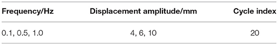
Table 2. The operating conditions of test 1.
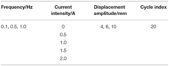
Table 3. The operating conditions of test 2 and test 3.
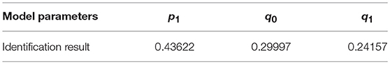
Table 4. Parameter identification of viscoelastic material.
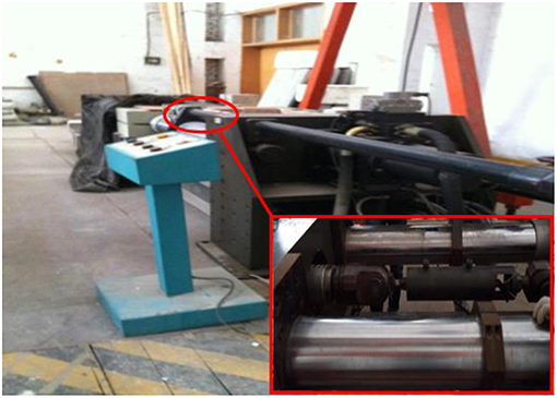
Figure 8. Diagram of the hydraulic servo loading system to the damper.
The Test Results
Figure 9 shows the hysteresis curves of the leakage-proof MR damper without MR fluid in operating conditions of 0.1, 0.5, and 1 Hz. The energy-consuming hysteresis curve of viscoelastic material is an oval. The hysteresis curve area is small but cannot be ignored, which means that the influence of viscoelastic material in the leakage-proof MR damper on its damping force cannot be ignored. With the increase of displacement amplitude, the hysteresis curve area of viscoelastic material increases, and as does its energy consumption. Besides, in the same displacement amplitude the hysteresis curve area of viscoelastic material increases with frequency, but the increase effect is not so apparent as amplitude change.
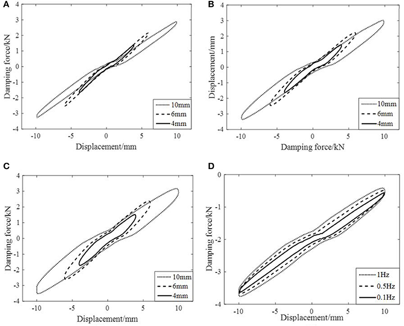
Figure 9. Hysteresis curves of the empty leakage-proof MR damper with varying frequency and amplitude. (A) Frequency 0.1Hz. (B) Frequency 0.5Hz. (C) Frequency 1Hz. (D) Amplitude 10mm.
Figures 10, 11 indicate the performance test results of the regular MR damper and the leakage-proof MR damper respectively. The outputting force of either one increases with current intensity, that is, the damper has an obvious MR effect. The force-displacement hysteresis curve of the regular MR damper is almost rectangular with a slightly bulging central part, which is caused by the viscous damping force provided by damper velocity, whereas that of the leakage-proof MR damper is a parallelogram with a certain inclination. And the force-displacement hysteresis curve of the leakage-proof MR damper has a sinking central part. The reason for the different shapes between the two results is that viscoelastic material provides additional stiffness for MR damper. When the displacement of the damper is larger, the damping force provided by viscoelastic material is larger. Therefore, the force-displacement hysteretic curve of the leakage-proof MR damper is a parallelogram with a certain inclination compared with that of the regular MR damper. In addition, the inner chamber pressure gradually increases in the process of the damper returning to the equilibrium position, which results in large warping deformation of the viscoelastic material, thus continuously weakening the damper's damping force. And when the displacement of the damper is 0, the weakening effect is greatest. Figure 11 also shows that with the increase of current intensity, the sinking degree of the hysteresis curve of the leakage-proof MR damper increases. This is because with the increase of current intensity, the inner pressure of the damper increases, warpage deformation of viscoelastic material also increases and the correction factor of pressure gradient decreases, leading to a more evident weakening effect on the damping force, which proves that it is reasonable to introduce a correction factor of pressure gradient into the mechanical model.
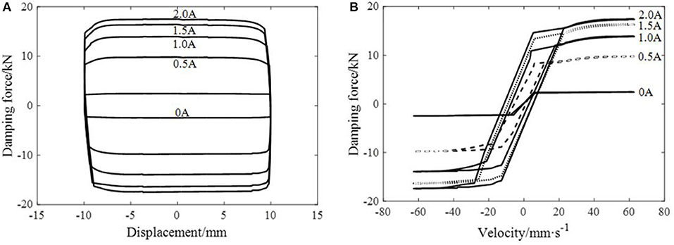
Figure 10. The hysteresis curve of the regular MR damper at frequency 1 Hz and amplitude 10 mm. (A) The relationship curve of displacement and damping force. (B) The relationship curve of velocity and damping force.
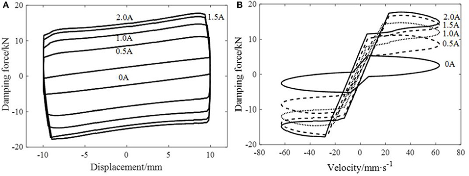
Figure 11. The hysteresis curve of the leakage-proof MR damper at frequency 1 Hz and amplitude 10 mm. (A) The relationship curve of displacement and damping force. (B) The relationship curve of velocity and damping force.
The same phenomenon can be reflected in the force-velocity hysteresis curve. With the maximum velocity, the curve end of the regular MR damper is a diagonal and the damping force is not weakened; while with the maximum velocity, the curve end of the leakage-proof MR damper has a descent stage, the damping force is weakened, and the force-velocity curve is a ring at the end, which means that viscoelastic material participates in energy consumption.
The fatigue property test on the MR damper adopts the load condition of frequency 5 Hz and amplitude 2 mm to apply a current intensity of 1 A. In the loading process, the sealing position of the damper is checked once every 50,000 cycle intervals. In the beginning, both the regular MR damper and the leakage-proof one keep a favorable sealing effect; after 200,000 fatigue tests some subtle nicks are found on the piston rod of the regular MR damper, but the damper is sealed well; after 500,000 fatigue tests, evident nicks appear on the piston rod of the regular MR damper and fluid leaks from them; after 550,000–600,000 fatigue tests, MR fluid begins to leak and drop, which means its seal is invalid, as is shown in Figure 12. Meanwhile, viscoelastic material at the sealing position on the leakage-proof MR damper and the joint between the piston and cylinder barrel are still in good condition, even after 2,000,000 loading cycles, as shown in Figure 13. The fatigue test for the MR damper indicates that the leakage-proof MR damper replaces the dynamic seal with a static seal which has a significant sealing property.
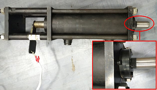
Figure 12. Diagram of the regular MR damper.
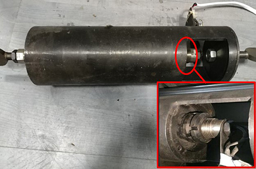
Figure 13. Diagram of the leakage-proof MR damper.
Parameter Identification of the Mechanical Model of the Leakage-Proof MR Damper
Constant Current Intensity Working Condition
According to the test results of the MR damper without fluid under every working condition, parameter identification in (15) can be accomplished by using the least squares method. The result is shown in Table 4:
From the above results, the storage modulus, consuming modulus, and loss factor can be obtained. Combining with the size parameters of viscoelastic materials, the formula for calculating the damping force of viscoelastic materials can be obtained.
According to the performance test result of the regular MR damper, the relationship between yield velocity and current is obtained, as shown in (19–22).
The least squares method is used to identify the parameters of the piecewise 3-order polynomial model. In order to ensure the accuracy of the polynomial calculation results, the relationship between the current and the coefficients of each piecewise polynomial is fitted by a second order polynomial, such as a = b + c * I + d * I2.The damping force of conventional dampers can be calculated by the parameters of Equation (14). The results of parameter identification are shown in the Table 5.
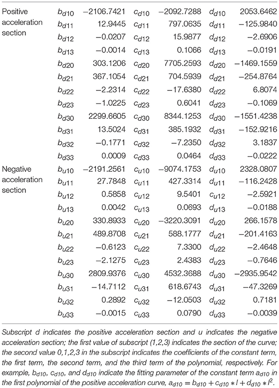
Table 5. Parametric identification of the piecewise 3-order polynomial model.
With those identified parameters, the mechanical model of the newly-established leakage-proof MR damper is verified. For the working condition of loading frequency 1 Hz, amplitude 10 mm and current intensity 2 A the maximum outputting force of the regular MR damper is 17.4 kN, implying that the initial inner pressure of the damper is 2.11 MPa. Through the fluid-structure interaction calculation the correction factor of pressure gradient under this working condition is obtained:
The damping force of the leakage-proof MR damper under this working condition is obtained from (17):
Figure 14 compares the results of testing and the mechanical model under this working condition. It indicates that the theoretical result is basically coincident with the testing result. The mechanical model can reflect that the damping force is weakened when the damper is at the equilibrium position, meaning that it is appropriate to introduce the correction factor of pressure gradient when establishing the mechanical model of the leakage-proof MR damper. This model can effectively describe its mechanical properties.
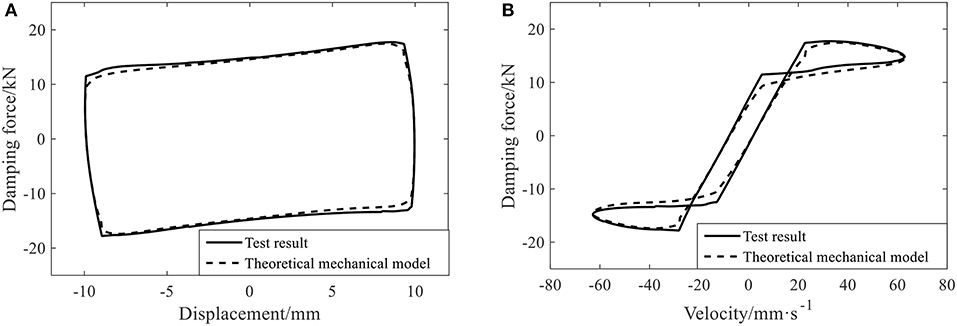
Figure 14. The comparison between the theoretical mechanical model and the test result of the leakage-proof MR damper. (A) Hysteresis curves of displacement and damping force. (B) Hysteresis curves of velocity and damping force.
Varying Current Intensity Working Condition
The tests prove that the sinking degree of the hysteresis curve of the leakage-proof MR damper is correlated to current intensity, that is, the more powerful the current intensity is, the greater sinking degree becomes in the middle of the curve. It means that the introduced correction factor of pressure gradient is also influenced by the impressed current intensity. The correction factor of pressure gradient under harmonic loads can be expressed as:
in which m(I) and n(I) are parameters concerning current intensity; ω is the angular frequency of the piston.
With data from the test, it is obtained by using the least squares method:
After obtaining two current intensity parameters in the correction factor, the mechanical model of the new leakage-proof MR damper can be obtained from (17):
Figure 15 is the comparison between the mechanical model and the test result under the working condition of frequency 1 HZ and amplitude 10 mm. It shows that the hysteresis curve obtained by the mechanical model under different working conditions is basically consistent with the curve from the test result, meaning that the newly-established mechanical model of the leakage-proof MR damper can well reflect the mechanical properties of the damper under different working conditions.
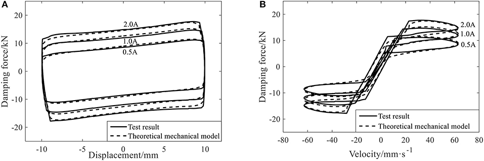
Figure 15. The comparison between the theoretical mechanical model and the test result of the leakage-proof MR damper under the varying current condition. (A) Hysteresis curves of displacement and damping force. (B) Hysteresis curves of velocity and damping force.
Conclusion
In order to solve the leaking problem of the MR damper, a leakage-proof MR damper is designed and created to accomplish this task fundamentally by using a softer viscoelastic material to provide a static seal for the damper. Considering that warpage deformation occurs to viscoelastic material under the load of its internal fluid, the correction factor of pressure gradient is proposed and then the mechanical model is established for the leakage-proof MR damper. After verification, the test results show that:
(1) The external cylinder barrel is vulcanized and connected with the piston by using viscoelastic material, and the traditional dynamic seal is replaced by a static seal. The test proves that its durability is greatly improved.
(2) Compared with the regular damper, the hysteresis curve of the leakage-proof MR grease damper has a sinking part in the middle, proving that warpage deformation of the viscoelastic material can weaken the damper capacity and the weakening effect increases with the current intensity. The correction factor of pressure gradient is introduced to consider that it is reasonable for warpage deformation of viscoelastic material and current intensity to influence the damping force of the MR damper.
(3) The calculated result of the mechanical model for the new leakage-proof MR damper is basically consistent with the test results, verifying the validity of the mechanical model of the leakage-proof MR damper and reflecting its mechanical properties well.
Data Availability
All datasets generated for this study are included in the manuscript and/or the supplementary files.
Author Contributions
JT initiated the research. ZL and JZ designed the experiments. KG, JL, and JG conducted the experiments. JT and ZL wrote the paper.
Funding
The research presented in this paper is supported by Natural Science Foundation of Hubei Province [grant number 2016CFA020]; Project of Ministry of Science and Technology [grant number 2018YFC0705601].
Conflict of Interest Statement
The authors declare that the research was conducted in the absence of any commercial or financial relationships that could be construed as a potential conflict of interest.
References
Carlson, J. D. (1999). Low-cost MR fluid sponge devices. J. Intell. Mater. Syst. Struct. 10, 589–594. doi: 10.1106/CG4J-V704-9LPH-GEC0
Carlson, J. D., and Spencer, B. F. Jr. (1996). “Magneto-rheological fluid dampers for semi-active seismic control,” in International Conference on Motion and Vibration Control (Chiba).
Çeşmeci., Ş, and Engin, T. (2010). Modeling and testing of a field-controllable magnetorheological fluid damper. Int. J. Mech. Sci. 52, 1036–1046. doi: 10.1016/j.ijmecsci.2010.04.007
Chang, K. C., Lai, M. L., Soong, T. T., Hao, D. S., and Yeh, Y. C. (1993). Seismic Behavior and Design Guidelines for Steel Frame Structures With Added Viscoelastic Dampers. Technical Report Nceer. Buffalo, NY: National Center for Earthquake Engineering Research, 93–0009.
Choi, S. B., Nam, M. H., and Lee, B. K. (2000). Vibration control of a MR seat damper for commercial vehicles. J. Intell. Mater. Syst. Struct. 11, 936–944. doi: 10.1106/AERG-3QKV-31V8-F250
Christensen, R. M., and Freund, L. B. (1982). Theory of Viscoelasticity. New York, NY: Academic Press.
Christie, M. D., Sun, S., Deng, L., Ning, D. H., Du, H., Zhang, S. W., et al. (2019). A variable resonance magnetorheological-fluid-based pendulum tuned mass damper for seismic vibration suppression. Mech. Syst. Signal Process. 116, 530–544. doi: 10.1016/j.ymssp.2018.07.007
Cunha-Filho, A. G., de Lima, A. M. G., Donadon, M. V., and Leão, L. S. (2016). Flutter suppression of plates using passive constrained viscoelastic layers. Mech. Syst. Signal Process. 79, 99–111. doi: 10.1016/j.ymssp.2016.02.025
Delgado, A., and San Andres, L. (2010). Identification of force coefficients in a squeeze film damper with a mechanical seal: large contact force. J. Tribol. 132:032201. doi: 10.1115/1.4001458
Deng, H., Wang, M., Han, G., Zhang, J., Ma, M., Zhong, X., et al. (2017). Variable stiffness mechanisms of dual parameters changing magnetorheological fluid devices. Smart Mater. Struct. 26:125014. doi: 10.1088/1361-665X/aa92d5
Giorgetti, A., Baldanzini, N., Biasiotto, M., and Citti, P. (2010). Design and testing of a MRF rotational damper for vehicle applications. Smart Mater. Struct. 19:065006. doi: 10.1088/0964-1726/19/6/065006
Hardy, E. J. R. (1951). The magnetic fluid clutch. Electr. Eng. 67, 1167–1167. doi: 10.1109/EE.1948.6444497
Hato, M. J., Choi, H. J., Sim, H. H., Park, B. O., and Ray, S. S. (2011). Magnetic carbonyl iron suspension with organoclay additive and its magnetorheological properties. Colloids Surf. A 377, 103–109. doi: 10.1016/j.colsurfa.2010.12.029
Hu, Z., Yan, H., Guo, X., Wang, X., and Wen, H. (2015). Rheological properties and stability of lithium-based magnetorheological grease with damping effect. Acta Petrol. Sin. 31, 166–171. doi: 10.3969/j.issn.1001-8719.2015.01.026
Iyengar, V. R., Alexandridis, A. A., Tung, S. C., and Rule, D. S. (2004). Wear testing of seals in magneto-rheological fluids©. Tribol. Trans. 47, 23–28. doi: 10.1080/05698190490279083
Jacob, R. (1951). Magnetic Fluid Torque and Force Transmitting Device. US, US2575360. Washington, DC: U.S. Patent Office.
Jeyasenthil, R., and Choi, S. B. (2018). A novel semi-active control strategy based on the quantitative feedback theory for a vehicle suspension system with magneto-rheological damper saturation. Mechatronics 54, 36–51. doi: 10.1016/j.mechatronics.2018.06.016
Jolly, M. R., Bender, J. W., and Carlson, J. D. (1999). Properties and applications of commercial magnetorheological fluids. J. Intell. Mater. Syst. Struct. 10, 5–13. doi: 10.1177/1045389X9901000102
Kelso, S. P., Denoyer, K. K., Blankinship, R. M., Potter, K., and Lindler, J. E. (2003). Experimental validation of a novel stictionless magnetorheological fluid isolator. Smart Struct. Mater. 2003 5052, 186–197. doi: 10.1117/12.483966
Liu, J., Wang, X., Tang, X., Hong, R., Wang, Y., and Feng, W. (2015). Preparation and characterization of carbonyl iron/strontium hexaferrite magnetorheological fluids. Particuology 22, 134–144. doi: 10.1016/j.partic.2014.04.021
Lu, G., Li, Y., and Song, G. (2011). Analysis of a magneto-rheological coupler with misalignment. Smart Mater. Struct. 20:105028. doi: 10.1088/0964-1726/20/10/105028
Mohamad, N., Ubaidillah Mazlan, S. A., Imaduddin, F., Choi, S. B., and Yazid, I. I. M. (2018). A comparative work on the magnetic field-dependent properties of plate-like and spherical iron particle-based magnetorheological grease. PLoS ONE 13:0191795. doi: 10.1371/journal.pone.0191795
Qu, W. L., Qin, S. Q., Tu, J. W., Liu, J., Zhou, Q., Cheng, H., et al. (2009). Intelligent control for braking-induced longitudinal vibration responses of floating-type railway bridges. Smart Mater. Struct. 18:125003. doi: 10.1088/0964-1726/18/12/125003
Samali, B., and Kwok, K. C. S. (1995). Use of viscoelastic dampers in reducing wind and earthquake-induced motion of building structures. Eng. Struct. 17, 639–654. doi: 10.1016/0141-0296(95)00034-5
Spencer, B. F., Yang, G., Carlson, J. D., and Sain, M. K. (1998). “Smart dampers for seismic protection of structures: a full-scale study,” in World Conference on Proceedings (Kyoto).
Stanway, R., Sproston, J. L., and Stevens, N. G. (1987). Non-linear modelling of an electro-rheological vibration damper. J. Electrostat. 20, 167–184. doi: 10.1016/0304-3886(87)90056-8
Sun, S. S., Ning, D. H., Yang, J., Du, H., Zhang, S. W., and Li, W. H. (2016). A seat suspension with a rotary magnetorheological damper for heavy duty vehicles. Smart Mater. Struct. 25:105032. doi: 10.1088/0964-1726/25/10/105032
Susan-Resiga, D., and Vékás, L. (2014). Yield stress and flow behavior of concentrated ferrofluid-based magnetorheological fluids: the influence of composition. Rheologica Acta 53, 645–653. doi: 10.1007/s00397-014-0785-z
Tezcan, S. S., and Uluca, O. (2003). Reduction of earthquake response of plane frame buildings by viscoelastic dampers. Eng. Struct. 25, 1755–1761. doi: 10.1016/j.engstruct.2003.07.001
Townsend, P., Suárez-Bermejo, J. C., Sanz-Horcajo, E., and Pinilla-Cea, P. (2018). Reduction of slamming damage in the hull of high-speed crafts manufactured from composite materials using viscoelastic layers. Ocean Eng. 159, 253–267. doi: 10.1016/j.oceaneng.2018.04.029
Tu, J. W., Liu, J., Qu, W. L., Zhou, Q., Cheng, H. B., and Cheng, X. D. (2011). Design and Fabrication of 500-kN Large-scale MR Damper. J. Intell. Mater. Syst. Struct. 22, 475–487. doi: 10.1177/1045389X11399942
Tudón-Martínez, J. C., and Morales-Menendez, R. (2015). Adaptive vibration control system for MR damper faults. Shock Vibr. 2015, 1–17. doi: 10.1155/2015/163694
Vereda, F., Segovia-Gutiérrez, J. P., de Vicente, J., and Hidalgo-Alvarez, R. (2016). Faceted particles: an approach for the enhancement of the elasticity and the yield-stress of magnetorheological fluids. Appl. Phys. Lett. 108:211904. doi: 10.1063/1.4952394
Wang, T. J., and Ma, L. S. (2004). Analytical solutions for axisymmetric bending of functionally graded circular/annular plates. Acta Mech. Sin. 36, 348–353. doi: 10.1109/SPAWDA.2013.6841128
Wang, W. R., Yan, X. Q., Sun, Z. H., and Jiang, Q. (2012). Analysis of vane hydraulic damp dynamic seal mechanism and performance influencing factors. Adv. Mater. Res. 530, 130–133. doi: 10.4028/www.scientific.net/AMR.530.130
Wen, Y. K. (1976). Method for random vibration of hysteretic systems. J. Eng. Mech. Div. ASCE. 102, 249–263.
Xu, Y. L., Qu, W. L., and Ko, J. M. (2000). Seismic response control of frame structures using magnetorheological/electrorheological dampers. Earthq. Eng. Struct. Dyn. 29, 557–575. doi: 10.1002/(SICI)1096-9845(200005)29:5<557::AID-EQE922>3.0.CO;2-X
Xu, Y. X., and Cao, M. (2004). Design calculation of magnetorheological damper. J. Shanghai Jiaotong Univ. 38, 1423–1427. doi: 10.1088/1009-0630/6/5/011
Xu, Z. D., Huang, X. H., Xu, F. H., and Yuan, J. (2019). Parameters optimization of vibration isolation and mitigation system for precision platforms using non-dominated sorting genetic algorithm. Mech. Syst. Signal Process. 128, 191–201. doi: 10.1016/j.ymssp.2019.03.031
Xu, Z. D., Liao, Y. X., Ge, T., and Xu, C. (2016). Experimental and theoretical study of viscoelastic dampers with different matrix rubbers. J. Eng. Mech. 142:04016051. doi: 10.1061/(ASCE)EM.1943-7889.0001101
Xu, Z. D., Sha, L. F., Zhang, X.-C., and Ye, H. H. (2013). Design, performance test and analysis on magnetorheological damper for earthquake mitigation. Struct. Control Health Monitor. 20, 956–970. doi: 10.1002/stc.1509
Xu, Z. D., Wang, D. X., and Shi, C. F. (2010). Model, tests and application design for viscoelastic dampers. J. Vibr. Control 17, 1359–1370. doi: 10.1177/1077546310373617
Yan, Y. X., Hui, L. X., Yu, M., Fu, J., and Dong, L. H. (2013). Dynamic response time of a metal foam magneto-rheological damper. Smart Mater. Struct. 22:025026. doi: 10.1039/9781849737760
Yang, G. (2001). Large-Scale Magnetorheological Fluid Damper for Vibration Mitigation: Modeling, Testing and Control (Dissertation). Abstracts International (B. F. Spence).
Yao, X. L., Tian, Z. D., Deng, Z. C., and Shen, Z. H. (2008). “Research on the mechanics characteristics of ship vibration reduction and impact resistance isolator based on MR,” in Vehicle Power and Propulsion Conference (Arlington, TX: IEEE).
Yazid, I. I. M., Mazlan, S. A., Kikuchi, T., Zamzuri, H., and Imaduddin, F. (2014). Design of magnetorheological damper with a combination of shear and squeeze modes. Mater. Design 54, 87–95. doi: 10.1016/j.matdes.2013.07.090
Zhang, R., and Soong, T. T. (1992). Seismic design of viscoelastic dampers for structural applications. J. Struct. Eng. 118, 1375–1392. doi: 10.1061/(ASCE)0733-9445(1992)118:5(1375)
Zhang, X. C., Zhang, X., Zhao, Y., Zhao, J., and Xu, Z. D. (2017). Experimental and numerical studies on a composite MR damper considering magnetic saturation effect. Eng. Struct. 132, 576–585. doi: 10.1016/j.engstruct.2016.11.055
Zhou, Y., Zhang, M., Lu, J. N., Wang, D. Y., and Wu, C. X. (2013). Experimental study on mechanical property of viscous damper. China Civil Eng. J. 46, 8–15. doi: 10.15951/j.tmgcxb.2013.01.010
Zhu, C. S. (2006). Experimental investigation on the dynamic behavior of a disk-type damper based on magnetorheological grease. J. Intell. Mater. Syst. Struct. 17, 793–799. doi: 10.1177/1045389X06055847
Keywords: magnetorheological (MR) damper, leak-proof, viscoelastic material, mechanical model, performance test
Citation: Tu J, Li Z, Zhang J, Gao K, Liao J and Gao J (2019) Development, Test, and Mechanical Model of the Leak-Proof Magnetorheological Damper. Front. Mater. 6:118. doi: 10.3389/fmats.2019.00118
Received: 26 February 2019; Accepted: 08 May 2019;
Published: 07 June 2019.
Edited by:
Zhao-Dong Xu, Southeast University, ChinaReviewed by:
Seung-Bok Choi, Inha University, South KoreaYongbo Peng, Tongji University, China
Peng Pan, Tsinghua University, China
Copyright © 2019 Tu, Li, Zhang, Gao, Liao and Gao. This is an open-access article distributed under the terms of the Creative Commons Attribution License (CC BY). The use, distribution or reproduction in other forums is permitted, provided the original author(s) and the copyright owner(s) are credited and that the original publication in this journal is cited, in accordance with accepted academic practice. No use, distribution or reproduction is permitted which does not comply with these terms.
*Correspondence: Jianwei Tu, dHVqaWFud2VpQHdodXQuZWR1LmNu