 Cheng Zhang1
 Pu Li1Shizhong Wei1*Long You1
 Xiaodong Wang1Feng Mao1Dongliang Jin1Chong Chen1Kunming Pan1Cheng Luo2Jingkui Li3
- 1National Joint Engineering Research Center for Abrasion Control and Molding of Metal Materials, School of Materials Science and Engineering, Henan University of Science and Technology, Luoyang, China
- 2School of Mechanical Engineering, Yangtze University, Jingzhou, China
- 3School of Materials Science and Engineering, Zhengzhou University, Zhengzhou, China
Effects of tempering temperature on impact wear of 30Cr3Mo2WNi hot-working die steel are investigated by SEM, TEM, hardness, and impact wear tests. From 300 to 680°C, the hardness of the steel decreases and the impact toughness increases with increasing tempering temperature, while a secondary hardening with maximum hardness, 48.6 HRC, is achieved at 550°C. Fatigue delamination wear is the main mechanism during the impact wear, and three typical damage features are identified with different tempering temperatures. Brittle fatigue cracks are easy to occur in the steels tempered at 300°C. Ductile fatigue cracks occur at medium temperatures. Surfaces of steel tempered are extruded at 680°C.
Background
Die steel is an important metal material in manufacturing industry. The service life of die steel mainly depends on the good toughness, high fatigue resistance, and high wear resistance (Zhu, 2001). For the hot-working die steel, most of the works focused on the strength, toughness and fatigue resistance of hot-working die steel, while the impact wear resistance was less studied (Bronfin et al., 1992; Ji and Wu, 2013). Wear resistance is of great significance for production and manufacturing (Luong and Heijkoop, 1981; Barrau et al., 2003; Wei et al., 2011). Excellent wear resistance can not only improve the service life of the die and reduce the cost, but also give the consistent quality of products. Moreover, the low strength and toughness of the material are mainly responsible for the failure of die steel. The heat treatments have an important influence on the wear resistance of the material (Mukhamedov and Tilabov, 2003; Cui et al., 2011; Xu et al., 2017a,b). In this paper, the impact wear behavior of 30Cr3Mo2WNi hot-working die steel at different tempering temperatures was studied by MLD-10 impact wear tester, and the effects of strength and toughness were investigated. Finally, the failure mechanism was discussed.
Experimental Detail
30Cr3Mo2WNi hot-working die steel was prepared by vacuum melting and electroslag remelting. The chemical compositions of steel are listed in Table 1. The steel is tempered at 300, 500, 550, 600, and 680°C after water quenching at 980°C.
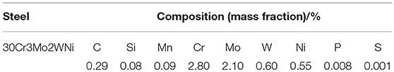
Table 1. Chemical compositions of the experimental steels.
The hardness of the tempered steels were measured by the HR150A Rockwell apparatus. The Vickers hardness of the samples were evaluated by a Digital Micro-hardness Tester HVS-1000A using a load of 25 g and a holding time of 15 s. The subsurface micro-hardness tests were performed on all the test samples up to a depth of 400 μm to study the extent of deformed zone. Charpy U-notch impact tests were carried out at room temperature using a pendulum impact testing machine (JB-300B), and the specimen dimensions are 10 × 10 × 55 mm.
Microstructure of specimens was studied using TESCAN-VEGA3SBH scanning electron microscopy (SEM) and Tecnai F20 high-resolution transmission electron microscopy (TEM). Specimens for TEM were taken from the surface layer with a thickness of 300 μm. The thin slice specimens were mechanically ground up to Ra = 0.1 μm (thickness of 50 μm). TEM specimens of Φ3 mm × 50 μm were taken from the middle of the thin slice specimens. Then, the thin foil specimens for the TEM observation were prepared using a twin-jet polisher (MTP-1A) in a solution of 95% acetic acid and 5% perchloric acid at −20 to −30°C, which were electropolished until a hole was obtained.
The impact wear test was performed with an experimental impact tester MLD-10 (Figure 1).
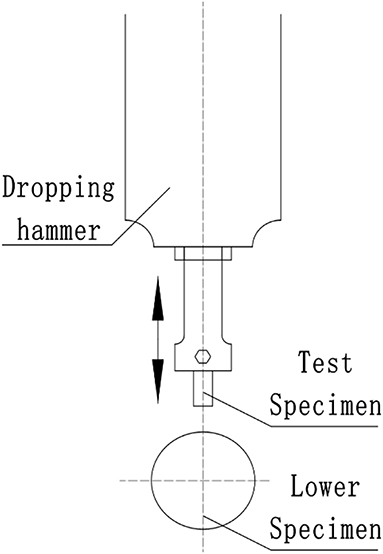
Figure 1. Schematic of the MLD-10 impact tester.
As shown in Figure 2, the test steel with a size of 10 × 10 × 30 mm is at the top of a grinding roller (GCr 15 steel with 60HRC hardness). A smooth surface was required for the specimen, and the axis of the specimen was perpendicular to the axis of the roller. During tests, the specimen moved up and down with the dropping hammer, and the roller rotated counterclockwise. No abrasive was added during tests. The experimental parameters were shown in Table 2. The wear loss of the specimens were measured.
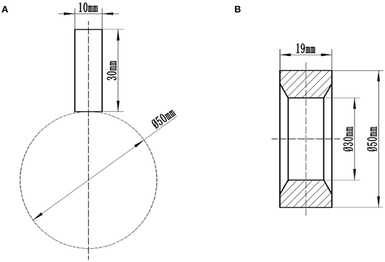
Figure 2. Schematic of the impact wear test. (A) Illustration of the testing structure; (B) Structure of the grinding roller.
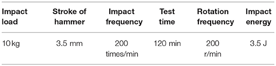
Table 2. Processing parameters during impact tests.
Three specimens were prepared from each tempered steel for impact wear test. Prior to wear test, the contact surfaces of samples were prepared by grinding using a 600-grit silicon carbide paper. The direction of grinding is perpendicular to the tangential direction of the cylindrical surface of the roller to ensure a same surface roughness before wearing. Then the samples were cleaned ultrasonically with alcohol for 20 min and dried. The weight of the samples was measured using an analytical balance (JA2000-4B) with an accuracy of 0.00001 g was used to weigh the samples. Before weighing, the worn specimens were cleaned with alcohol and dried to remove the stains and iron scraps attached to the surface. The amount of wear is assessed by the weight loss (ΔW) using equation (1):
where W0 is the mass of the sample before wear, Wi is the mass after wear in each time, and is obtained by the average of the three samples.
The worn surfaces and fatigue cracks in the subsurface were examined by SEM. As soon as the worn surfaces were observed after the impact wear test, the specimens were sectioned perpendicularly to the worn surfaces from the impact samples for observation of crack morphology. The subsurface micro-hardness tests were performed to study the extent of deformed zone.
Results and Discussion
Scenario 1: Variations of Hardness and Impact Toughness With Tempering Temperatures for 30Cr3Mo2WNi Steel
Table 3 and Figure 3 show the Rockwell hardness and impact energy of 30Cr3Mo2WVNi steel varying with tempering temperatures. The hardness of specimen tempered at 500°C, 46.4HRC, is 1.0 HRC lower than that treated at 300°C. A secondary hardening with maximum hardness of 48.6 HRC is achieved when the specimen is tempered at 550°C. As the tempering temperature increases, the hardness decreases. The hardness of the sample tempered at 600°C, 45.7HRC, is 3 HRC lower than that tempered at 550°C. When the tempering temperature exceeds 600°C, the hardness of test steel decreases drastically.
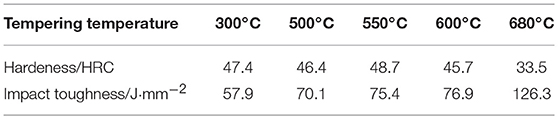
Table 3. Hardness and impact toughness of samples tempered at different temperatures.
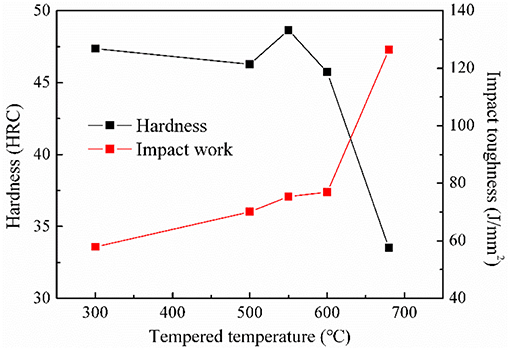
Figure 3. Variation of hardness and impact toughness with tempering temperature for 30Cr3Mo2WNi steel.
The toughness of the steel increases slowly when tempered is <600°C, and the impact energy of the steel is between 70.1 and 76.9 J·mm−2 from 500 to 600°C. However, the impact toughness of the material increases rapidly above 600°C. The impact energy of the specimens tempered at 680°C is even up to 126.3 J·mm−2.
Scenario 2: Evolution of the Microstructure With Tempering Temperature in 30Cr3Mo2WNi Steel
SEM images of the specimens tempered at different temperatures are shown in Figure 4. The microstructure of steel tempered at 300°C is mainly consisted of tempered martensite and a small amount of carbides. With the increase of tempering temperature, the tempered troostite and fine carbides develop in the microstructure, as shown in the TEM image by yellow frame in Figure 5. The secondary hardening occurs when the steel is tempered at 550°C, leading to a slight increase of the hardness. When the steel is tempered at 680°C, the size of carbides increases obviously, which are mainly distributed at grain boundaries and in grains. And the microstructure transforms to tempered sorbite, and thus the hardness decreases greatly.
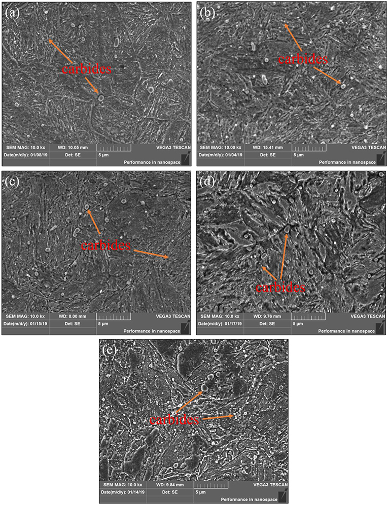
Figure 4. Microstructures of 30Cr3Mo2WNi steel treated at different tempering temperatures. (a) 300°C; (b) 500°C; (c) 550°C; (d) 600°C; (e) 680°C.
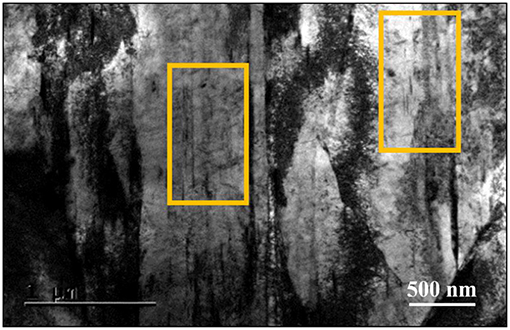
Figure 5. TEM photograph of microstructure after tempering at 550°C.
Scenario 3: Changes of Impact Wear Properties of 30Cr3Mo2WNi Steel With Tempering Temperature
Table 4 and Figure 6 show the weight losses of the specimens after impact wear test for 60 and 120 min at different tempering temperatures. As the tempering temperature increases, the wear losses decreases first and then increases when the wear time is 60 min. The wear loss of the steel tempered at 550°C is the lowest. The wear losses of specimens tempered at 300°C (19.1 mg) and 680°C (19.0 mg) are relatively the largest.
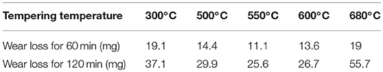
Table 4. Variation of impact wear loss with tempering temperature of 30Cr3Mo2WNi steel.
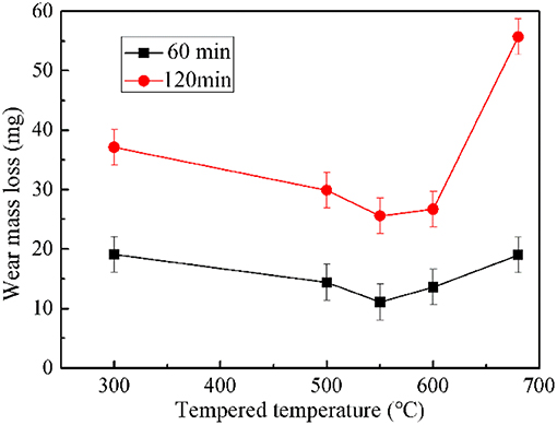
Figure 6. Variation of impact wear loss with tempering temperature of 30Cr3Mo2WNi steel.
For the time of 120 min, the wear behavior is similar to that of 60 min. However, when the tempering temperature exceeds 600°C, the wear rate increases greatly. Wear loss of specimen tempered at 680°C the reaches 55.7 mg, which is as twice as the wear loss at 550°C. It shows that the impact wear mechanism of test steel changes with the increasing of temperature.
It can be seen that the hardness of test steel reaches its peak due to secondary hardening from Figure 3, thus the wear mass loss is the least when tempered at 550°C. The wear loss is almost the same between the steels tempered at 500 and 600°C. In general, the wear resistance is proportional to the hardness of material, that is, the higher the hardness of the material is, the better the wear resistance is Modi et al. (2003) and Sevim and Eryurek (2006). However, hardness of the specimens tempered at 300°C is 15 HRC higher than that at 680°C, but the wear loss of the two specimens differs by only 0.1 mg. Compared to the steel tempered at 300°C, the hardness of the material is lower and the wear loss is still less when tempered at 550 and 600°C. Therefore, it indicates that there is no obvious relationship between the hardness and the impact wear loss of the materials in this work.
Scenario 4: Morphologies of Impact Wear for the 30Cr3Mo2WNi Steel at Different Tempering Temperatures
The microstructures of the wear surfaces are shown in Figure 7. The wear surface of 30Cr3Mo2WNi steel treated at different tempering temperatures cracked severely after wear for both 60 and 120 min, and the fatigue flaking was going to spall. The wear mechanism is mainly fatigue wear.
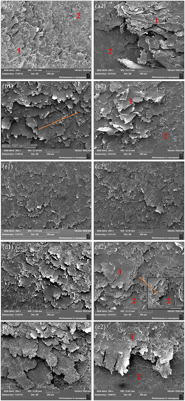
Figure 7. Microstructures of impact wear surfaces at various tempering temperature for 30Cr3Mo2WNi Steel. (a1,a2) 300°C 60 min, 120 min; (b1,b2) 500°C 60 min, 120 min; (c1,c2) 550°C 60 min, 120 min; (d1,d2) 600°C 60 min, 120 min; (e1,e2) 680°C 60 min, 120 min.
In Figure 7, the worn surface and the worn subsurface can be identified simultaneously in most cases and they are marked as area 1 and area 2, respectively. Most of the wear surface has peeled off after 60 min owing to the low toughness of the specimen tempered at 300°C, as shown in Figure 7a1. Therefore, the wear loss after 60 min is comparable with that tempered at 680°C. Among the five specimens with impact time of 60 min, it can be found that the wear surface tempered at 550°C is the smoothest, and shows less fatigue delamination, smaller crack size, and short fracture edge. In Figure 3, for the steel tempered at 550°C, the optimized mechanical properties of the steel are obtained, in chich the crack is difficult to form and expand, therefore the wear loss is the lowest. The length of fatigue cracks increases on the surface of specimens tempered at 500 and 600°C. The surface of the crack is flat, and there are no secondary cracks in the magnification of Figure 7b1, indicating that both the strength and the toughness are favorable, resulting in a low wear loss. The wear surface of specimen tempered at 680°C is rough and full of large cracks. Besides, there are large amounts of faults between the fragments, which indicate that a large part of fatigue fragments have spalled, then the wear loss is large.
The wear morphologies of specimens at different temperatures for 120 min are approximately the same as that for 60 min. In addition to the specimen tempered at 550°C, other four specimens show relatively smooth and green metal matrix. Some of the worn subsurface are relatively flat, indicating that they have not been significantly damaged, as shown in the magnification of the area 2 in Figure 7d2. Other subsurface layers have shown the features of plastic deformation and adhesive wear, indicating that the next cycle of wear is in progress (Archard and Hirst, 1956). The wear loss of specimens tempered at 680°C is much higher than other four specimens after wear for 120 min in Figure 6. It is argued that the wear mechanism has changed.
Figure 8 shows that the lateral side of wear surface of specimens tempered at 680°C for 120 min, and it shows a very serious plastic extrusion (So et al., 2008). After tempered at 680°C, the resistance to impact deformation of the steel is poor due to the low hardness. At the same time, the repeated impact and tangential friction induce a temperature excursion that in turn softens the surface, then extrudes the material from the contact surface under high stress, resulting in severe wear loss. However, other four samples show no obvious plastic extrusion owing to high hardness after test for 120 min.
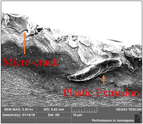
Figure 8. Micro-crack and plastic extrusion at the edge of wear surface.
Scenario 5: Fatigue Spalling Mechanism of 30Cr3Mo2WNi Steel Under Impact Condition
The essence of wear is the process of hardening and spalling of the wear surface. That is, the initiation, propagation and coalescence of micro-cracks in the wear surface and subsurface are important processes (Suh, 1977). Therefore, in order to demonstrate the failure mode of the test steels, it is beneficial to investigate the damage state of the wear surface and subsurface.
Figure 9 shows the cross section morphology of the steels after wear. Under the impact compression, the fatigue cracks can form at the surface and subsurface, then propagate and coalesce at a small angle along with the shear stress, resulting in flaking spall. Three typical impact damage features are presented in Figure 9.
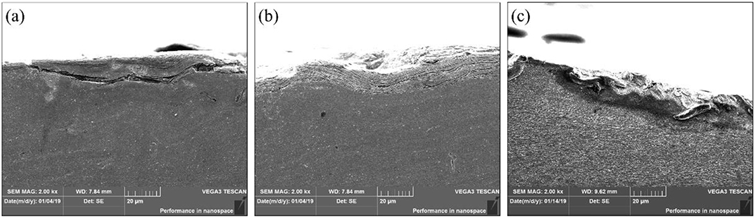
Figure 9. Cross-sectional micrographs. (a) Brittle crack; (b) Ductile crack; (c) Plastic extrusion.
The cracks are long and straight in Figure 9a, and the flake debris are thicker, and the edge is clear and smooth (Yang et al., 1995). This typical crack mainly occurs on the surface of the low tempered specimens, probably resulted from the higher hardness and lower toughness of the specimens with lower tempered temperature. Due to work hardening, the surface of the specimen becomes harder and more brittle under the continuous impact, leading to the formation of a persistent larger stress at the crack tip.
It can be seen from Table 5 that the largest difference of micro-hardness 140 HV between the wear surface and the matrix of the steels tempered at 300°C, indicating a larger deformation, and a higher stress concentration. As soon as the fatigue crack is formed, it will propagate rapidly parallel to the surface under the shear stress, and finally cause surface spalling.
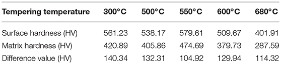
Table 5. Micro-hardnesses of wear surface and matrix of specimens tempered at different temperatures.
With the increase of tempering temperature, the toughness of the specimen increases, and the resistance to crack propagation is enhanced. Therefore, the crack is short and winding, showing obvious splitting structures, as shown in Figure 9b.
The hardness of steel is lower after tempered at high temperature, which reduces the resistance to plastic deformation, such as cutting, and chipping. Thus, the micro-cracks are prone to initiate from the plows and pits under impact (Huang et al., 2001). After crack initiation and coalescence, the metal surface with lower hardness will collapse and be extruded when impacted, resulting in severe wear loss, as shown in Figure 9c.
Figure 10 shows the schematic of the fatigue spalling during impact wear. At the initial stage of wear, fatigue cracks mainly nucleate on the surface, or subsurface (Figure 10A). With the increase of impact time, the plastic deformation occurs in the surface under the combination of the impact, and shear stress. Then the stress concentration increases and the cracks propagate, approximately parallel to the surface (Figure 10B). Subsequently, surface and subsurface cracks further expand and coalescence, resulting in fatigue spalling, and serious wear loss (Figure 10C).
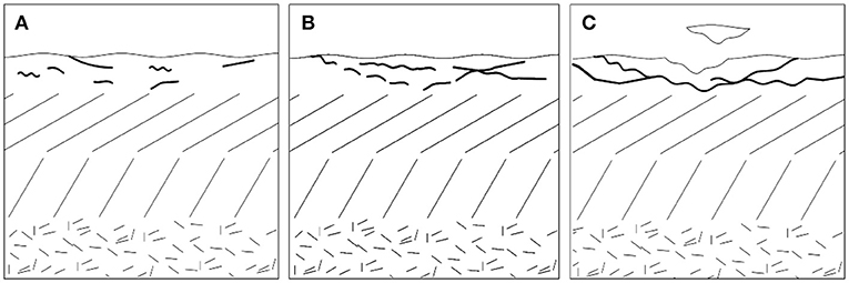
Figure 10. Schematic of the fatigue spalling during the impact wear. (A) Crack initiation; (B) Crack propagation and coalescence; (C) Crack spalling.
Conclusions
In this work, the impact wear behaviors of the 30Cr3Mo2WNi hot-working die steel has been studied under different conditions, and a few conclusions can be drawn from the results:
1. With the increase of tempering temperature, the hardness of the steel decreases and the toughness increases. The secondary hardening occurs when the steel is tempered at 550°C, which leads to an increased hardness of the steel.
2. Fatigue delamination wear is the impact wear mechanism during tests. With the increase of tempering temperature, the impact wear loss of the steel decreases first and then increases. The wear loss of the specimen tempered at 550°C is the lowest. The wear morphology of the specimen tempered at 680°C are the roughest one, and plastic extrusion appears at the lateral side, resulting in the largest wear loss.
3. Three damage features are identified for the specimens tempered at different temperatures. Brittle fatigue cracks are easy to occur at low tempering temperature of 300oC. Ductile fatigue cracks occurs at medium temperatures. Surface extrusion develops for the steel tempered at high temperature.
Data Availability
All datasets generated for this study are included in the manuscript and/or the supplementary files.
Author Contributions
CZ: operation of experiments and mechanism analysis. PL: preparation of specimens and experiment operation. SW: formulation of experimental scheme. LY: mechanical property. XW: operation of experiments. FM: heat treatment of steels. DJ: microstructure analysis. CC: mechanism analysis. KP: microstructure analysis. CL: preparation of specimens. JL: mechanism analysis.
Funding
The work was supported by the Key Scientific and Technological Project of Henan Province (Nos. 192102210009, 182102210043) and open science and technology cooperation project of Henan province (182106000024).
Conflict of Interest Statement
The authors declare that the research was conducted in the absence of any commercial or financial relationships that could be construed as a potential conflict of interest.
References
Archard, J. F., and Hirst, W. (1956). The Wear of metals under unlubricated conditions. Proc. R Soc. A 236, 397–410. doi: 10.1098/rspa.1956.0144
Barrau, O., Boher, C., Gras, R., and Rezai-Aria, F. (2003). Analysis of the friction and wear behaviour of hot work tool steel for forging. Wear 255, 1444–1454. doi: 10.1016/S0043-1648(03)00280-1
Bronfin, B. M., Eme'yanov, A. A., and Yu Pyshmintsev, I. (1992). Microstructural aspects of the fracture toughness and fatigue resistance of high-strength low-carbon steels. Mater. Sci. 27, 513–515. doi: 10.1007/BF00726467
Cui, X. H., Wang, S. Q., Wei, M. X., and Yang, Z. R. (2011). Wear characteristics and mechanisms of H13 steel with various tempered structures. J. Mater. Eng. Perform. 20, 1055–1062. doi: 10.1007/s11665-010-9723-0
Huang, J. F., Fang, H.-S., Xu, P., and Zheng, Y. K. (2001). Effect of Si on wear resistance of bainitic cast steel under high stress impact. J. Iron Steel Res. 13, 40–45.
Ji, T. Y., and Wu, X. C. (2013). Microstructure and mechanical properties of modified-H13 hot working die steel. J Iron Steel Res. 25, 31–38.
Luong, L. H. S., and Heijkoop, T. (1981). The influence of scale on friction in hot metal working. Wear 71, 93–102. doi: 10.1016/0043-1648(81)90142-3
Modi, O. P., Mondal, D. P., Prasad, B. K., Sing, M., and Khaira, H. K. (2003). Abrasive wear behaviour of a high carbon steels: effects of microstructure and experimental parameters and correlation with mechanical properties. Mater. Sci. Eng. A 343, 235–242. doi: 10.1016/S0921-5093(02)00384-2
Mukhamedov, A. A., and Tilabov, B. K. (2003). Effect of heat treatment on the wear resistance of parts with hard-alloy coatings. Metal Sci. Heat Treat. 45, 109–111. doi: 10.1023/A:1024567521385
Sevim, I., and Eryurek, I. (2006). Effect of fracture toughness on abrasive wear resistance of steels. Mater Design 27, 911–919. doi: 10.1016/j.matdes.2005.03.009
So, H., Chen, H. M., and Chen, L. W. (2008). Extrusion wear and transition of wear mechanisms of steel. Wear 265, 1142–1148. doi: 10.1016/j.wear.2008.03.002
Suh, N. P. (1977). An overview of the delamination theory of wear. Wear 44, 1–16. doi: 10.21236/ADA050250
Wei, M.-X., Wang, S.-Q., Wang, L., and Chen, K.-M. (2011). Effect of microstructures on elevated-temperature wear resistance of a hot working die steel. J. Iron Steel Res. Int. 18, 47–53. doi: 10.1016/S1006-706X(12)60021-1
Xu, L., Fan, X., Wei, S., Liu, D., Zhou, H., Zhang, G., et al. (2017a). Microstructure and wear properties of high-speed steel with high molybdenum content under rolling-sliding wear. Tribol. Int. 116, 39–46. doi: 10.1016/j.triboint.2017.07.002
Xu, L., Wei, S., Xiao, F., and Zhou, H. (2017b). Effects of carbides on abrasive wear properties and failure behaviours of high speed steels with different alloy element content. Wear 376, 968–974. doi: 10.1016/j.wear.2017.01.021
Yang, Y.-Y., Fang, H.-S., Zheng, Y.-K, Yang, Z.-G., and Jiang, Z.-L. (1995). The failure modeis induced by white layers during impact wear. Wear 185, 17–22. doi: 10.1016/0043-1648(94)06586-1
Keywords: tempering, impact wear, die steel, hardness, wear mechanism, fatigue crack
Citation: Zhang C, Li P, Wei S, You L, Wang X, Mao F, Jin D, Chen C, Pan K, Luo C and Li J (2019) Effect of Tempering Temperature on Impact Wear Behavior of 30Cr3Mo2WNi Hot-Working Die Steel. Front. Mater. 6:149. doi: 10.3389/fmats.2019.00149
Received: 30 April 2019; Accepted: 13 June 2019;
Published: 04 July 2019.
Edited by:
Shengqiang Ma, Xi'an Jiaotong University, ChinaReviewed by:
Lin L. U, Shanghai Research Institute of Materials (SRIM), ChinaKe Wang, Chongqing University, China
Jianjun Zhang, Xihua University, China
Copyright © 2019 Zhang, Li, Wei, You, Wang, Mao, Jin, Chen, Pan, Luo and Li. This is an open-access article distributed under the terms of the Creative Commons Attribution License (CC BY). The use, distribution or reproduction in other forums is permitted, provided the original author(s) and the copyright owner(s) are credited and that the original publication in this journal is cited, in accordance with accepted academic practice. No use, distribution or reproduction is permitted which does not comply with these terms.
*Correspondence: Shizhong Wei, d3N6QGhhdXN0LmVkdS5jbg==