 Himanshi Jangir
 Amarjeet Bhardwaj
 Janakarajan Ramkumar3
 Sabyasachi Sarkar
 Mainak Das
- 1Design Program, Indian Institute of Technology Kanpur, Kanpur, India
- 2Department of Biological Sciences and Bioengineering, Indian Institute of Technology Kanpur, Kanpur, India
- 3Department of Mechanical Engineering, Indian Institute of Technology Kanpur, Kanpur, India
- 4Nano Science and Synthetic Leaf Laboratory at Downing Hall, Centre for Healthcare Science and Technology, Indian Institute of Engineering Science and Technology, Howrah, India
- 5Design Program and Biological Sciences & Bio-Engineering, Indian Institute of Technology Kanpur, Kanpur, India
Developing ‘carbon lithium sulfide composite (C-Li2S)’ cathode is a promising strategy for Li-S battery. Quite interestingly, when Li and S are caged in a heavily nitrogen-doped reduced graphene oxide (NDRGO) matrix derived from Tassar silk cocoon, the composite (NDRGO-Li-S) electrode behaves like a supercapacitor. In this work, we first optimized the concentrations of sulfur and then introduced molybdenum in the NDRGO matrix to develop a stable NDRGO-Mo-Li-2S (where 2 stands for 2M) composite electrode. The electrode design process utilized the concepts of “embedded redox couples” and “induced electron transfer”; a putative strategy to alter internal electron-shuttling kinetics for applications in various charge storage devices; where a time of electron-shuttling is the key. In NDRGO-Mo-Li-2S composite the charge transport occurs via “induced electron transfer,” where Li+, is an external oxidant, provoking the inter atom electron transfer between Mo(VI), the internal oxidant, and S(-II), the internal reductant in Mo-S redox couple. This redox reaction is reversed using NDRGO, an external reductant inducing inter atom electron flow across [Mo(V)–(S2)] to complete the starting to product and back cycle. Such a redox cycle is competent for the flow of electrons in a lasting charge storage material through this unique bio-inorganic hybrid approach.
Introduction
A significant amount of research has undergone in Li-S battery; having sulfur as the cathode (positive electrode), lithium as the anode (negative electrode) and an aprotic organic solvent of lithium salt as an electrolyte (Rauh et al., 1979; Peled and Yamin, 1983; Peramunage and Licht, 1993; Shim et al., 2002; Armand and Tarascon, 2008; Aurbach et al., 2009). The major shortcomings of the Li-S battery are the following: (a) unstable nature of the sulfur cathode. (b) polysulfide shuttling problem. (c) challenges to select the appropriate electrolyte. (d) protecting the lithium anode or scouting for a more stable anode. These shortcomings have been dealt with in detail in recent reviews on the Li-S battery (Ely et al., 2018).
The present work involves the design and development of stable cathode material for Li-S battery. During the last decade, two major approaches have been attempted to improve the sulfur cathode. In the first approach, the sulfur cathode is being stabilized by forming a carbon-sulfur composite (Ji et al., 2009). While, in the second, Li2S cathode is preferred over the sulfur cathode (Hassoun and Scrosati, 2010).
Li2S suffers from poor electrical conductivity and sluggish electrochemical performance. Li2S-carbon composite electrodes are currently being investigated to improve stability and electrochemical activity (Geng et al., 2018; Jangir et al., 2018; Li et al., 2018a,b,c; Luo et al., 2019; Shi et al., 2019; Zhou et al., 2019). In one of our earlier works, to improve the conductivity and stability of Li2S, we developed a synthetic approach viz., we synthesized Li2S in a conductivity cage of heavily nitrogen doped reduced graphene oxide (NDRGO) derived from the wild Tassar silk cocoon (Jangir et al., 2018). We sequentially entrapped equimolar lithium and sulfur in NDRGO, resulting in the formation of NDRGO-Li-S composite. While testing the electrochemical performance of the NDRGO-Li-S composite, to our surprise, we observe that the composite behaved as a better supercapacitor as compared to NDRGO (Jangir et al., 2018). This finding sets the tone for the present research and opens up a few critical questions (a–c), that are enumerated below:
(a) In the earlier work, we used equimolar lithium and sulfur to develop the NDRGO-Li-S composite (Jangir et al., 2018). If we vary the content of sulfur while keeping the concentration of lithium constant, how will it influence the electrochemical performance of the composite?
(b) Since leaching of sulfur from both carbon-sulfur and Li2S-carbon cathode is a persistent problem; ‘how much sulfur can be optimally anchored in an NDRGO matrix, so that without any sulfur spillover, it retains stability and provides long term optimal electrochemical performance?’
(c) Exploring an alternative strategy to increase the stability of Li2S-carbon composite?
In the present work, we have addressed the questions a and b, by varying the concentration of sulfur and testing the electrochemical performance of the newly synthesized composites. The schematic of the strategy has been shown in Figure 1. While addressing question c, we drew our inspiration from two fundamental concepts: (i) electron shuttling through redox couples as observed in a biological membrane, (ii) induced electron transfer.
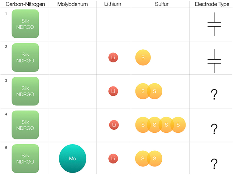
Figure 1. Overall experimental design and the strategies followed to develop a stable silk NDRGO, Li, S electrode. The heavily nitrogen doped reduced graphene oxide (NDRGO) derived from silk is used as a conductivity cage. Superscript 1 indicates NDRGO, a supercapacitor electrode. Superscript 2, stands for NDRGO-Li-S composite obtained from equimolar doping of Li and S on the NDRGO matrix. Superscript 3, stands for 1M Li and 2M S doping on the NDRGO matrix, i.e., NDRGO-Li-2S. Superscript 4, stands for 1M Li and 4M S doping on the NDRGO matrix, i.e., NDRGO-Li-4S. Superscript 5, stands for Mo, 1M Li and 2M S doping on the NDRGO matrix, i.e., MDRGO-Mo-Li-2S.
In the subsequent section, we will discuss each of these aspects and how these concepts assisted us in designing a stable Li2S-carbon composite electrode.
(i) Electron shuttling in biological membranes is carried out by a series of embedded redox couples, mainly iron-sulfur (Fe-S), cytochromes, and copper proteins. These metalloproteins are used with different redox potentials to control the electron flow and sometimes the energy used in these steps are coupled to derive relevant biochemical reactions. The direction of electron flow is a function of the redox potential. The time an electron takes to travel from point A to point B in a chloroplast or mitochondrial membrane, though very fast, yet depends on the number of redox couples which it encounters during its journey. Thus, the capacitive discharge of such a membrane is a function of the number of redox couples present in the membrane (Stryer, 1999). Inspiration could be drawn from such biological membranes; to introduce redox couples in synthetic electrode membranes to make it more stable and vary the time of electron transfer. The specific question we ask, is the following: could we stabilize sulfur by introducing an atom ‘X’ in the NDRGO matrix, so that sulfur forms redox couples with ‘X’ viz., S-X. In such a situation, the electron kinetics will be altered, as well as sulfur will be stabilized as an internally embedded redox couple. We chose molybdenum (Mo) as our ‘X’ atom; with the assumption that it will form a two-dimensional MoS2 structure on top of the NDRGO sheet, where MoS2 will function as a redox couple, stabilizing the sulfur. So what we targeted, is to develop an electrode matrix with an extended bond system having the key players as NDRGO, Mo, Li, and S.
(ii) Quite interestingly, in such extended bond systems, transfer of electrons can be induced by different kinds of operations. This brings us to the least known concept, viz., “Induced electron transfer,” introduced by Professor Henry Taube, through his famous book entitled “Electron Transfer Reactions of Complex Ions in Solution”; published in 1970 (Taube, 1970). Such an electron transfer across a central atom and an adjoining donor atom or ligand in a compound is induced by an external redox agent (either oxidant or reductant), that also participates in the said reaction. In such arrangement, the external redox system, say an oxidant provokes and initiates the electron transfer process across the central atom and ligand in the compound leading to a product, and the process is reversed by a second external reductant to bring back the product to starting compound (Taube, 1970; Sarkar and Ansari, 1986; Chandrasekaran et al., 1987; Ansari et al., 1988a,b,c; Miller and Min, 2009). The external oxidant and reductant, using such transitioning redox chemistry, maintained an interdependent two-ways electron shuttling arrangement necessary for storage devices. Such an approach could be exploited to control the time of electron transfer, which is the key for different kinds of charge storage electrodes viz., battery, supercapacitor, capattery.
Here, we have designed and engineered a bio-hybrid electrode by amalgamating these two above mentioned basic aspects of electron kinetics. The electrode consists of an embedded molybdenum-sulfur (Mo-S) redox couple; along with silk cocoon derived heavily nitrogen doped reduced graphene oxide (NDRGO) and lithium (Li), an electronegative and an electro-positive species, respectively. This electrode exhibits “induced electron transfer”; where Li+ acts as an external oxidant, providing the necessary driving force to provoke the inter atom electron transfer between Mo(VI), as internal oxidant, and S(-II), as internal reductant in Mo-S redox couple and NDRGO functions as external reductant assists in reversing the process and bringing the system back to its original configuration.
The work presented here is divided into three sub-sections as enumerated below:
Sub-section one: A detailed procedure has been discussed highlighting the design and engineering aspects of four different variants of the bio-hybrid electrode material. Further electrochemical characterization of these electrode materials have been carried out, and the results were compared to choose the best electrode configuration from the pool of four electrodes.
Sub-section two: Based on the comparative analysis in previous sub-section, a detailed structural analysis and life cycle studies were conducted for the NDRGO-Mo-Li-2S electrode configuration.
Sub-section three: A putative mechanism of electron transport on the electrode surface has been discussed on the basis of “induced electron transfer” and “shuttling of an electron through embedded redox couple” as observed in NDRGO-Mo-Li-2S electrode.
Experimental
Synthesis of Electrode Material and Electrochemical Characterization
Preparation of NDRGO
Tassar silk cocoon were obtained from the forest reserves of the state of Chhattisgarh in India as described in our previous work (Roy et al., 2014; Sahu et al., 2015; Dubey et al., 2018; Jangir et al., 2018). The dead pupae was removed and the Tassar silk cocoon was cut into small pieces and was then put into a crucible. The crucible was put into a furnace and the furnace was purged with argon for 45 min. Then the temperature of the furnace was slowly raised to 400 °C under argon atmosphere and that temperature was fixed to completely char the cocoon pieces for 4 h. The heating was then discontinued and the furnace was allowed to cool under argon till it attained room temperature. The bio-charred sample was removed from the crucible and was ground to form powdery fine particles using pestle and mortar. This sample was then packed and sealed into a Whatman filter paper to create a thimble-like package and the solid sample was placed inside and sealed to close the opening. That was repeatedly washed with acetone using a soxhlet extractor to remove any organic by-product formed under charring. The residual sample was allowed to dry and then oxidized using nitric acid. For this, 1 g of the washed sample was slowly added in portion into 30 ml of HNO3 to control the exothermic reaction with the evolution of nitric dioxide fumes and when it is virtually subsided, the mixture was allowed to stand for 18–24 h at 40 °C. The acid was then removed under slow evaporation to solidify the mass which was then washed with water, methanol and acetone sequentially, and finally dried in a desiccator. This sample on analysis is found to be ~15% nitrogen doped graphene oxide. This was then reduced using hydrazine hydrate. About 0.5 g of the above sample was treated in 30 ml of hydrazine hydrate at approximately 40 °C for 12 h. The insoluble reduced graphene oxide so formed was washed with water followed by methanol and acetone sequentially and dried in a desiccator. This sample is termed as nitrogen doped reduced graphene oxide (NDRGO) (Roy et al., 2014; Sahu et al., 2015; Dubey et al., 2018; Jangir et al., 2018).
Preparation of NDRGO-Li-S, NDRGO-Li-2S, NDRGO-Li-4S
Around 200 mg of NDRGO was added in previously argon purged 15 ml of dimethylformamide (DMF) and continuously stirred at 50 °C for 40 min under argon. Then, 21 mg of Li metal was added into it and stirred for 20 min. To this, 100, 200 and 400 mg of sulfur powder, respectively, added for NDRGO-Li-S, NDRGO-Li-2S, NDRGO-Li-4S compositions, respectively. In each case the final ternary mixture (NDRGO, Li and S) was stirred for 2 h, to obtain the final product. Then, DMF was removed by washing with benzene and the sample was stored in oxygen and moisture free chamber. Based on the sulfur ratio used, we got three products as NDRGO-Li-S, NDRGO-Li-2S, and NDRGO-Li-4S. NDRO-Li-S synthesis has been discussed in detail in one of our previous publications (Jangir et al., 2018).
Preparation of NDRGO-Mo-Li-2S
As mentioned in the preceding paragraph, around 200 mg of NDRGO was added in previously argon purged 15 ml of dimethylformamide (DMF) and stirred at 50 °C for 40 min under argon. Forty milligram ammonium molybdate tetra hydrate was added to this mixture and further stirred in an argon environment for 20 min, while maintaining a temperature of 50 °C. Following this, 21 mg Li was added. The reaction was allowed to progress for next 20 min and after this 200 mg S was added, and the reaction was continued for next 2 h. The final product was washed with benzene and stored for further use in vacuum desiccator.
Electrode Preparation, Electrolyte Preparation, and Electrochemical Characterization
(i) Electrode preparation: Electrode materials were coated on one side of the graphite sheet (current collector) of size 1.5 cm*1.5 cm. Only 5 mg of electrode material was coated.
(ii) Electrolyte preparation: 1 part of 1-butyl 3- methyl imidazolium tetrafluoroborate [BMIM]BF4 in 10 parts of acetonitrile (ACN) was used as electrolyte. This was prepared in argon atmosphere by gently dissolving in ACN for 30 min (Wang et al., 2012; Jangir et al., 2018).
(iii) Electrochemical characterization: Electrochemical analysis was performed using ZIVE SP1 single channel electrochemical workstation. We used three electrode configuration with platinum as counter electrode and a reference electrode. Two analyses were performed: cyclic voltammetry (CV) followed by charge-discharge study. CV was performed in the voltage range of −1.5 V to +1.5 V at a scan rate of 5 milliVolt per second (mV/s). Charge discharge analyses (CC/CC mode) were performed using a constant charging and discharging current of 5 milliampere (mA) in the voltage range of −1.5 V to +1.5 V. Long-term charge discharge analysis was performed for NDRGO-Mo-Li-2S at a constant charging and discharging current of 0.2 mA in a voltage range of −0.5 V to +1.0 V. In addition, for NDRGO-Mo-Li-2S, CV was performed at different scan rates of 100, 50, 5, and 1 mV/s. Also, charge discharge curves were recorded for 5, 1, and 0.2 mA constant current in a voltage window of −0.5 V to +1.0 V.
Electrode Material Characterization
Field emission gun scanning electron microscopy (FE-SEM) was performed using JSM-7100F (JEOL Ltd.). Transmission electron micrographs were obtained from FEI Technai 20 U Twin Transmission Electron Microscope (TEM). X-ray photoelectron spectroscopy (XPS) was done using PHI 5000 Versa probe II FEI Inc. instrument. X-ray diffraction (XRD) pattern was obtained using PANanlyticalX’Pert instrument.
Results and Discussion
This results section has been divided into three subsections as discussed earlier in the “introduction.”
Sub-section 1
Design principles and engineering of five different variants of bio-hybrid electrode material and the electrochemical characterization (Figures 1–6).
The electrode designing process was initiated from a naturally derived material of biological origin viz., Tassar silk cocoon. Bio-charred silk cocoon is a rich source of heavily nitrogen (~16%) doped reduced graphene oxide (NDRGO) matrix, exhibiting remarkable fluorescence, soft ferromagnetism, and supercapacitor properties (Roy et al., 2014; Sahu et al., 2015; Dubey et al., 2018; Jangir et al., 2018). We discovered that doping equimolar lithium and sulfur (NDRGO-Li-S) in NDRGO matrix improves supercapacitor properties (Jangir et al., 2018).
In the present work, we initially attempted to improve the electrochemical properties of NDRGO-Li-S complex, by increasing the S content from 1 to 2M and 4M, thus resulting in two new complexes NDRGO-Li-2S and NDRGO-Li-4S, respectively. The transmission electron micrographs of NDRGO-Li-S, NDRGO-Li-2S, and NDRGO-Li-4S composites are shown in Figures 2a–c. All the composites showed a 2-D sheets like geometry ascertaining the presence of NDRGO matrix. In our earlier works on NDRGO and NDRGO-Li-S, we observed similar results (Roy et al., 2014; Sahu et al., 2015; Dubey et al., 2018; Jangir et al., 2018). The distribution of the chemical moieties in these complexes were further verified by their XRD signatures as shown in Figure 3. The XRD traces highlight the elemental distribution of these electrode materials.
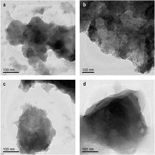
Figure 2. Representative TEM images: (a) NDRGO-Li-S. (b) NDRGO-Li-2S. (c) NDRGO-Li-4S. (d) NDRGO-Mo-Li-2S.
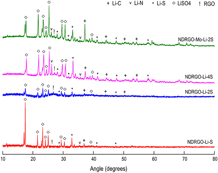
Figure 3. XRD pattern of the synthesized composites.
Next, we performed CV analysis for NDRGO, NDRGO-Li-S, NDRGO-Li-2S, and NDRGO-Li-4S (Figure 4). Since in our earlier work, NDRGO and NDRGO-Li-S showed superior supercapacitor properties, we tested supercapacitor properties of NDRGO-Li-2S and NDRGO-Li-4S. Initially CV analysis was performed using a typical super capacitor testing protocol viz., voltage range of −1.5 V to +1.5 V with a scan rate of 5 mV/s. We made two important observations at this stage of experimentation. CV analysis showed that NDRGO-Li-2S performs better than NDRGO, NDRGO-Li-S and NDRGO-Li-4S (Figure 4A). But for NDRGO-Li-4S composite, a significant amount of sulfur spillage took place in the electrolyte during electrochemical measurement, as observed by the change in the color of the electrolyte to yellow (Figure 4B). After running the electrode for few cycles, we observed unstable recordings and detachment of electrode material from the graphite sheet (as can be observed at the bottom of the beaker shown in Figure 4). In one of the earlier work, Medenbach et al. (2018) reported similar sulfur spillage. Due to unstable nature of the NDRGO-Li-4S composite, this composition was not included for further experiments. The material indeed showed initial promise but further work is needed to stabilize the composite. Followed by CV, we performed a charge discharge analysis for NDRGO-Li-S, NDRGO-Li-2S, and NDRGO-Li-4S and compared the results (Figure 4C). A constant charging and discharging current of 5 mA in the voltage range of −1.5 V to +1.5 V was used for analyzing the results viz., typically used for testing super capacitor (Stoller and Ruoff, 2010).
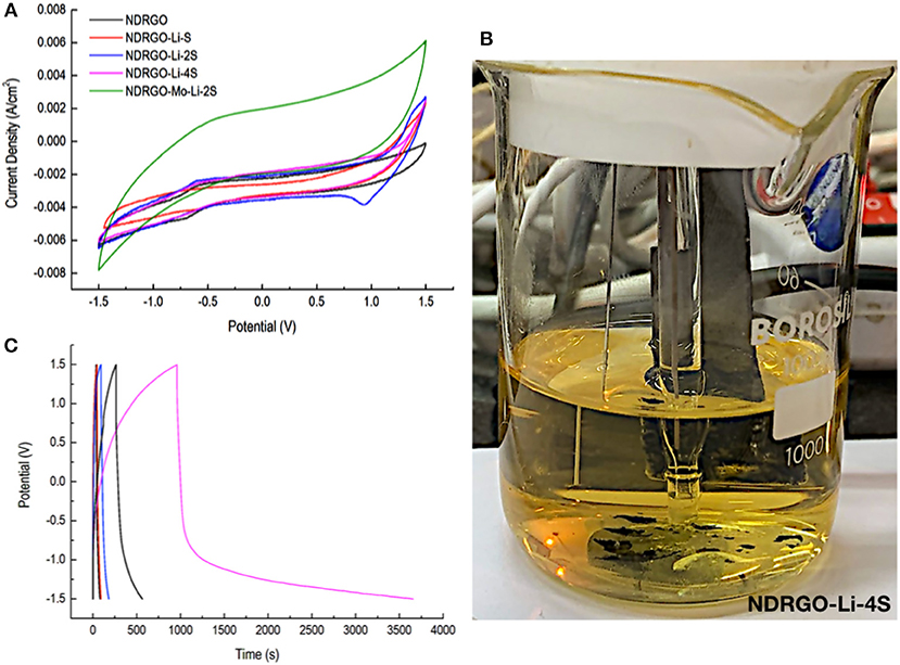
Figure 4. Electrochemical characterization of all the composites. CV was performed in the voltage range of −1.5 V to +1.5 V at a scan rate of 5 millivolt (mV) per second. Charge discharge analyses (CC/CC mode) were performed using a constant charging and discharging current of 5 milliampere (mA) in the voltage range of −1.5 V to +1.5 V. (A) Cyclic voltammogram analysis. (B) Sulfur spillage in NDRGO-Li-4S composite. (C) Charge-discharge analysis.
While NDRGO-Li-2S performed better than NDRGO-Li-S, but to our surprise, NDRGO-Li-4S completely deviated from super capacitor behavior. But the unstable nature of the complex prevented us from exploring it further. Based on CV and charge-discharge results, we proceeded with NDRGO-Li-2S composite.
We further tried to improve the stability and supercapacitive property which we observed in NDRGO-Li-2S complex. Without altering the structural conformation, viz., layered sheet-like structure of this complex, we plan to introduce another 2-D sheet like matrix (MoS2) into it. Recently, to enhance the photo-catalytic activity of reduced graphene oxide (rGO), a similar approach has been reported, where a rGO-MoS2 composite has been prepared by Cravanzola et al. (2016). In our present work, to achieve this, we chronologically introduced molybdenum into the NDRGO matrix before lithium and sulfur because of the following reasons (Figure 1):
(a) Assuming that the assembly of the atoms follows a layer by layer strategy, the larger size of Mo on top would have hampered the interaction of smaller Li and S atoms with the electrolyte.
(b) Mo being multi-valent would provide varied binding sites for upcoming Li and S atoms.
(c) By this strategy, Li is sandwiched between two multi-valent atoms viz., Mo and S.
(d) Introducing a larger Mo atom between NDRGO matrix and Li, increased the distance between highly electropositive Li and highly electronegative N.
This newly synthesized NDRGO-Mo-Li-2S showed surprising deviation from super capacitor like properties in terms of cyclic voltammogram (Figure 4A) and charge-discharge characteristics (Figure 4C) than any of its siblings’ like NDRGO, NDRGO-Li-S, and NDRGO-Li-2S. What was even more surprising was the stability of this new composite viz., NDRGO-Mo-Li-2S. Since NDRGO-Mo-Li-2S composite did not show any super capacitor like feature, we designed additional experiments to test its electrical nature.
Next, we performed CV for NDRGO-Mo-Li-2S at different scan rate and further determined the normalized current density (Figure 5). Upon normalization of the current density, we observed certain striking differences viz., at 50 and 100 mV/s scan, one does not see any difference. But as we lower the scan rate to 5 mV/s and then further down to 1 mV/s, we started to see a complete deviation from higher scanning rates viz., 50 and 100 mV/s. Thus this critical information, indicated that the electrode material is more suitable for devices requiring slow charge kinetics viz., more like a battery electrode, or something between battery and supercapacitor (capattery) (Akinwolemiwa et al., 2015), the goal with which we initiated our research (a stable Li2S-C composite).
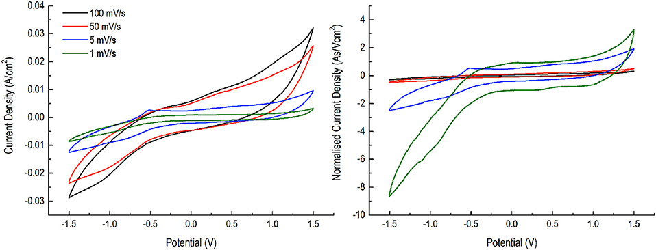
Figure 5. CV analysis of NDRGO-Mo-Li-2S at 1, 5, 50, 100 mV/s and normalized current density (As/Vcm2).
In the light of this result (Figure 5), we performed a charge discharge analysis (CC/CC mode) of the material using a constant charging and discharging current of 5, 1, and 0.2 mA in the voltage range of −0.5 V to +1.0 V (Figure 6). The voltage window of 1.5 V was selected, since we observe that at low current, the electrode perform optimally at this range. As we lowered down the current, the material behaved typically like a battery material, a NDRGO-Mo-Li-2S cathode. What is most interesting revelation is that, it is feasible to engineer the charge-discharge kinetics with little molecular tweaking. Next challenging question for us was to explore the structure of NDRGO-Mo-Li-2S.
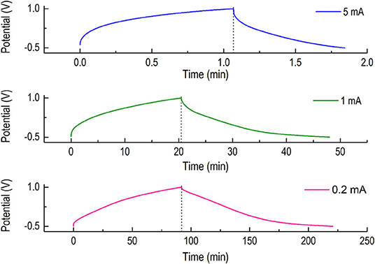
Figure 6. Charge discharge analyses (CC/CC mode) were performed for NDRGO-Mo-Li-2S using a constant charging and discharging current of 5, 1, and 0.2 mA in the voltage range of −0.5 V to +1.0 V.
Sub-section 2
Detailed structural analysis and life cycle studies of NDRGO-Mo-Li-2S electrode.
Based on the electrochemical results, we further explored the structural characteristics of NDRGO-Mo-Li-2S (Figure 7). The key question we asked is “how introduction of Mo completely alters the stability and functional efficiency of the material?”
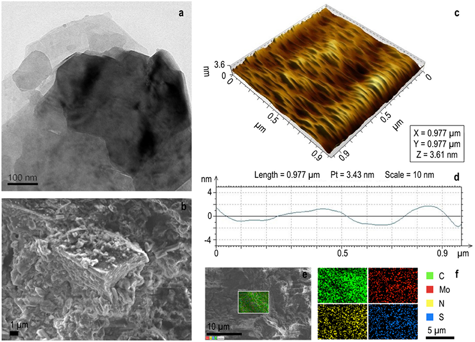
Figure 7. Structural analysis of NDRGO-Mo-Li-2S. (a) Representative TEM image. (b) Representative FESEM image showing lamellar structure. (c) AFM image. (d) Height profile of the material in AFM. (e) Representative site used for elemental analysis. (f) Elemental analysis for C, N, Mo and S.
In NDRGO-Mo-Li-2S, a weak 002 peak appears at 26.5 °C in its XRD, indicating significant deoxygenation and the presence of the nitrogen atoms in the crystal lattice of graphene. This intercalation of nitrogen, resulted in increased distance between the graphite layers (Figure 3). It showed 2D stacked sheet like morphology in TEM (Figure 2d and Figure 7a). Further, SEM images showed lamellar geometry (Figures 7b,f). The depth profile of the matrix in AFM showed an average height of 3.6 nm (Figure 7c). The presence of S, Mo, C, and N was further verified by elemental analysis.
In order to analyze the surface chemical features of NDRGO-Mo-Li-2S, we performed a detailed XPS. Table 1 shows the binding energies corresponding to the bonds observed in NDRGO-Mo-Li-2S complex in the XPS spectra. The assignment of XPS peaks were validated with NIST X-ray photoelectron spectroscopy database (Naumkin et al., 2012).
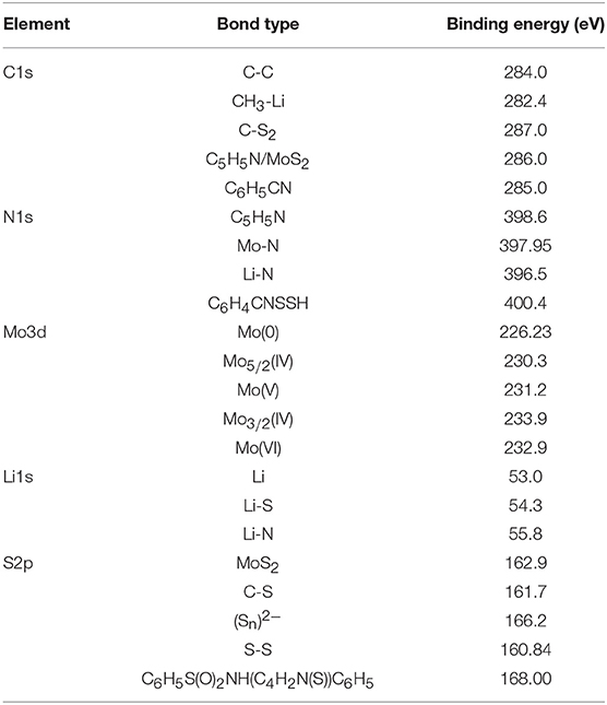
Table 1. The binding energies obtained from the narrow spectra for each constituting elements of NDRGO-Mo-Li-2S.
The broad spectrum of XPS shows the presence N1s, C1s, Mo3d, S2p, Li1s (Figure 8A). The narrow spectra of C1s, N1s, Mo3d, Li1s, S2p are shown in Figures 8B–F.
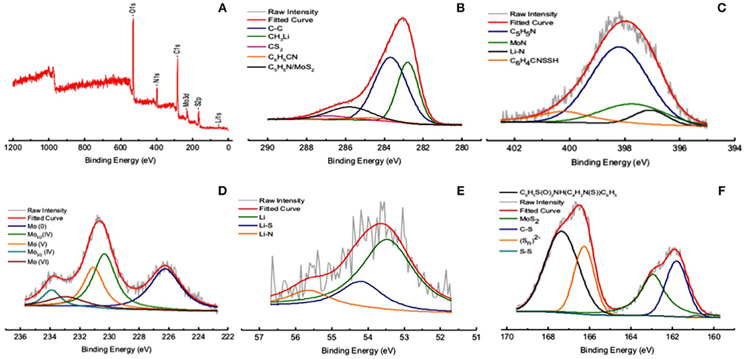
Figure 8. XPS analysis of NDRGO-Mo-Li-2S. (A) Broad spectrum. Narrow spectra of (B) C1s. (C) N1s. (D) Mo3d. (E) Li1s. (F) S2p.
The initial hypothesis we laid out in the synthesis of NDRGO-Mo-Li-2S, to our satisfaction corroborates with its structural and bonding characteristics. The TEM, FESEM, and AFM showed extensive stacking of sheets, this is in line with the characteristics of NDRGO (Figure 7, Table 1) and MoS2 as evident in Figure 8F, Table 1. Mo exists in elemental as well as in IV, V, VI oxidation states (Figure 8D). Sandwiching of Mo between NDRGO and S is also observed (Figure 8B). The integration of Mo into the NDRGO matrix is highly evident (Figure 8F). Addition of Li after Mo has served to be advantageous as, Li being a smaller atom managed to percolate through the Mo sieve and bond with C and highly electronegative N atoms of NDRGO; it has also stayed above Mo and bonded with S (Figure 8E). The role of Mo in the NDRGO-Mo-Li-2S complex, seems like that of an atomic ligand that holds the constituent atoms at a distance from each other. An analogy could be drawn where Mo acts like a dielectric with carbon-nitrogen on one side and lithium-sulfur on the other side making a series of molecular capacitors within the NDRGO-Mo-Li-2S matrix.
The multivalency and the proposed atomic coordinating ability of Mo in NDRGO-Mo-Li-2S complex led us to study the life of the material at a lower current. The charge discharge experiment was tried to match the real life conditions, where, the NDRGO-Mo-Li-2S electrode (in three cell electrode configuration) was maintained under argon atmosphere continuously for 23 days. The time course of the experiment is illustrated in Table 2. The experiment was done in eight sets (I-VIII) and a gap of around 12 h was given between each set. During this gap phase, the system was left idle. The gap was purposefully introduced in order to validate, whether system can restart from its original configuration after undergoing an idle phase. We obtained a total of 133 cycles of which representative traces of 7 cycles viz., 3rd, 23rd, 43rd, 63rd, 83rd, 103rd, 123rd cycles are shown in Figures 9A–G. A comparative profile of the charge-discharge curve for cycle number 2 and 133 is shown in Figure 9H. We observed that the system performed consistently throughout the experimentation process and the material maintained its original configuration. Such results prove the stability of NDRGO-Mo-Li-2S electrode.
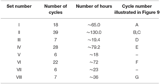
Table 2. The time course of charge-discharge cycles for NDRGO-Mo-Li-2S at 0.2 mA in the potential window, +1 V to −0.5 V.
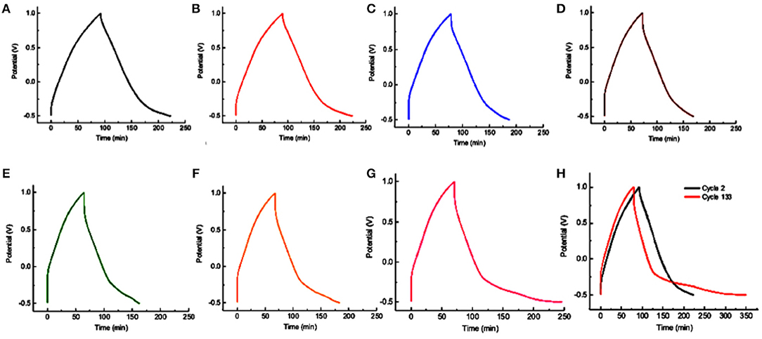
Figure 9. Long-term charge-discharge cycles for NDRGO-Mo-Li-2S. (A) Cycle number 3. (B) Cycle number 23. (C) Cycle number 43. (D) Cycle number 63. (E) Cycle number 83. (F) Cycle number 103. (G) Cycle number 123. (H) Comparing the charge-discharge profile of cycle number 2 vs. cycle number 133.
One interesting aspect could be seen while carefully looking at the tendency of the charge discharge curves viz., the capacity decayed at the former cycle testing and increased at the latter cycle testing. It seems like the system is behaving like programmable matter in order to attain its most stable configuration. In this process, the entire quaternary mixture it slowly moving to a more stable and ordered state through several metastable states reflecting the transition from one type of electron transfer (supercapacitor like) to another kind of electron transfer (battery type). These transition classify the material into the range of cappatery like material.
Sub-section 3
A putative mechanism of electron transport on the electrode surface of NDRGO-Mo-Li-2S.
This interesting behavior of NDRGO-Mo-Li-2S, prompted us to propose a putative model of electron transfer, where we attempted to address the following question: How introduction Mo changed the charge-discharge time and area within CV curve? These properties may be related to the stability of the charge and electron release processes which could be explained by introducing very unique “induced electron transfer” reactions (Taube, 1970; Sarkar and Ansari, 1986; Chandrasekaran et al., 1987; Ansari et al., 1988a,b,c; Miller and Min, 2009). Here, the sustained electron flux is maintained by invoking the role of Li as an external oxidant, Li+ (I). This provokes the intra-atom electron transfer across Mo(VI)-S(II) bond, where Mo(VI) is the internal oxidant and S(II), is the internal reductant. For electron book keeping, it can be presumed that two sulfide ions release two electrons getting self oxidized to disulfide (S2) (II) anion. The released two electrons are shared one each by the external oxidant, Li+ (I) to create Li and internal oxidant Mo(VI) to create Mo(V). Such redox reaction is reversed using NDRGO as external reductant (releasing electron) to induce intra-atom reverse electron flow across [Mo(V)-(S2)] to regenerate the starting [Mo(VI)-S(II)] material to complete the cycle. Here NDRGO readily oscillates between its graphene oxide and reduced graphene oxide states. Interestingly all the oxidation states of these elements proposed in such electron transfers associated in this quaternary complex have been identified using XPS. Therefore, such redox cycle is competent for the flow of electrons in a lasting charge storage material through this unique bio-inorganic hybrid approach. In Figure 10, a putative mechanism of induced electron transfer in NDRGO-Mo-Li-2S is shown.
Figure 10. Induced electron transfer in N-doped reduced graphene oxide-Mo-Li-S electrode; where m stands for number of electrons.
An important question which arises from this study is ‘what kind of benefits ‘induced electron transfer’ could offer in development of lithium-sulfur batteries?’ It has been well-established that sulfur attached to metal plays varied electron transfer reaction. Sulfur has the unique distinction when S2− (Sulfide anion) gets oxidized to elemental sulfur (S0) and in that situation S2− and S0 combine to create . Interestingly if you add more S0 then there is a creation of . This is the polysulfide chemistry and can be extended to and further. Interestingly for species like , it dissociates to 2. Therefore, sulfide under electrochemical environment can display different species from neutral to anionic including free radical. Such chemistry has been exploited in induced electron transfer. For such special type of electron transfer for electron bookkeeping, if one assume the sulfide gets oxidized then the electron released can be shared by two different metal for example the chemistry of Li+ to Li must be compensated by involving one another electron capture by Mo in + state to produce in (N-1)+ state. These two together can control the two electrons released from say 2S2− to create + 2 Electrons. So the question is the entire process is taking place if one can conceive the idea that in a molecule of lithium sulfide, if lithium ion is treated as external oxidant and sulfide as the internal reductant; in this situation the extra electron generated can be shared by the used Mo ion. Here Mo act as internal oxidant. The reaction can be concerted if a ternary mixture like Li, S, Mo act in unison. Here the distinction of internal and external redox partner may not arise, but the shuttling of electron from sulfide to Li and Mo can effectively proceed. The entire electron transfer has different rate and where the rate of one half sulfur to Li may differ from Sulfur to Mo. Such a system can experience the electron transfer difference at different scan rate. A fine tuning of these ternary mixture can be made if there is nitrogen remain very near to these ternary system, which can affect the electron transfer. The nitrogen atom can do it readily because it has different oxidation state. However, there cannot be a fraction of electron that can participate moving from one atom to another and for that reason the delocalization of electron density of the entire system has to be taken into account. The measurement of such electron distribution is not straight forward because under the varied scan rate such overall electron density varies. For simple Li2S cathode, such induced electron transfer may not be feasible because one has to maintain electron book keeping. So the concept of external oxidant and internal oxidant sharing electrons generated by internal reluctant and external reductant is not varied because for induced electron transfer concept there is the involvement of one internal oxidant and one external oxidant to share electron generated by the lone internal reductant. For conventional Li2S cathode it is highly unlikely that one can invoke induced electron transfer process. Therefore to sustain such reaction in Li system other elements are nowadays routinely exploited for example the addition of iron, phosphate and further the transition metal-organic frame work (Geng et al., 2018; Jangir et al., 2018; Li et al., 2018a,b,c; Luo et al., 2019; Shi et al., 2019; Zhou et al., 2019).
Further with reference to NDRGO-Mo-Li-2S complex, we can see that the capacitor capacity has been greatly improved after adding Mo. Among them, the composition of sulfur has obtained the optimum result. Is it feasible to optimize the concentration of Mo? From atom conservation the extra addition of Mo will not enhance the electron transfer behavior. This is simple for the reason that Mo can play multi electron donor and acceptor and therefore an optimal stoichiometry like 1 unit of Mo in the system is expected.
Here it is worth highlighting the exceptional electrochemical stability of the heavily nitrogen doped carbon derived from a natural protein polymer (silk cocoon) and its transition metal sulfide composites; as stability of such composite always remained a challenge for different energy applications (Cravanzola et al., 2016; Dubey et al., 2018; Geng et al., 2018; Jangir et al., 2018; Li et al., 2018a,b,c; Luo et al., 2019; Shi et al., 2019; Zhou et al., 2019).
Summary and Conclusions
In summary, we have successfully designed and engineered a stable bio-hybrid electrode material which integrates lithium (Li), sulfur (S), and molybdenum (Mo) in a matrix of biological origin viz., silk cocoon derived heavily nitrogen (16%) doped reduced graphene oxide (NDRGO); thus resulting in NDRGO-Mo-Li-2S. The electron shuttling on this electrode is govern by a lesser explored route viz., “induced electron transfer” regulated by an electropositive Li, electronegative NDRGO and an embedded redox couple of Mo-S. We believe that such a bio-hybrid approach is a step toward developing sustainable, eco-friendly high energy electrode materials.
Data Availability
All datasets generated for this study are included in the manuscript/supplementary files.
Author Contributions
This work is part of HJ’s doctoral research. HJ and MD conceived the idea and designed the experiments. HJ developed the idea and conducted the synthesis, carried out the structural, chemical and electrochemical characterizations. AB conducted the synthesis and purification of the compounds. JR helped in TEM and AFM. SS and MD conceived the concept of electron transfer shuttle and role of Mo. HJ, SS, and MD wrote the manuscript.
Funding
HJ acknowledges Ministry of Human Resource and Development, Government of India for her doctoral fellowship research.
Conflict of Interest Statement
The authors declare that the research was conducted in the absence of any commercial or financial relationships that could be construed as a potential conflict of interest.
Acknowledgments
Authors are thankful to the staff at Advance Centre for Material Science, Indian Institute of Technology Kanpur, India. We sincerely acknowledge the help offered to us by Mr. DD Pal for XPS, Mr. A Tiwari for XRD facility, and Mr. Mitesh for FESEM work. This work was an integral part of HJ’s doctoral thesis.
References
Akinwolemiwa, B., Peng, C., and Chen, G. Z. (2015). Redox electrolytes in supercapacitors. J. Electrochem. Soc. 162, A5054–A5059. doi: 10.1149/2.0111505jes
Ansari, M. A., Chandrasekaran, J., and Sarkar, S. (1988a). Sulfur mediated induced electron transfer reactions in tungsten-sulfur systems: synthesis and reactivity of bis (tetraethylammonium) bis (disulfido) dioxodi-m-sulfidodi tungstate. Polyhedron 7, 471–476. doi: 10.1016/S0277-5387(00)81193-6
Ansari, M. A., Chandrasekaran, J., and Sarkar, S. (1988b). Concealed induced internal electron transfer reaction in the synthesis of bis (diethyldithiocarbamato) (disulfido) oxotungsten from diethylammonium oxotrithiotungstate(2-) and carbon disulfide with oxygen. Inorg. Chem. 27, 763–764.
Ansari, M. A., Chandrasekaran, J., and Sarkar, S. (1988c). One pot synthesis of dinuclear tungsten(V) compounds containing [W2XY(μ -S)2]2+ (X = O, S; Y = O, S) cores by thermally induced internal electron-transfer processes. Bull. Chem. Soc. Jpn. 61, 2265–2267. doi: 10.1246/bcsj.61.2265
Armand, M., and Tarascon, J. M. (2008). Building better batteries. Nature 451, 652–657. doi: 10.1038/451652a
Aurbach, D., Pollak, E., Elazari, R., Salitra, G., Kelley, C. S., and Affinito, J. (2009). On the surface chemical aspects of very high energy density, rechargeable Li–Sulfur batteries. J. Electrochem. Soc. 156, A694–A702. doi: 10.1149/1.3148721
Chandrasekaran, J., Ansari, M. A., and Sarkar, S. (1987). Aging of ammonium tetrathiomolybdate (VI) in air: an example of induced electron transfer by external oxidant. J. Less Common Met. 134, L23–L25. doi: 10.1016/0022-5088(87)90570-4
Cravanzola, S., Cesano, F., Magnacca, G., Zecchina, A., and Scarano, D. (2016). Designing rGO/MoS2 hybrid nanostructures for photocatalytic applications. RSC Adv. 6, 59001–59008. doi: 10.1039/C6RA08633K
Dubey, A., Jangir, H., Verma, S., Saxena, M., Sarkar, S., Philip, D., et al. (2018). A green route for production of ‘carbon based charge storage nanomaterials’. Mater. Renew. Sustain Energy. 7:20. doi: 10.1007/s40243-018-0127-7
Ely, T. O., Kamzabek, D., Chakraborty, D., and Doherty, M. F. (2018). Lithium–sulfur batteries: state of the art and future directions. ACS Appl. Energy Mater. 1, 1783–1814. doi: 10.1021/acsaem.7b00153
Geng, P., Zheng, S., Tang, H., Zhu, R., Zhang, L., Cao, S., et al. (2018). Transition metal sulfides based on graphene for electrochemical energy storage. Adv. Energy Mater. 8:1703259. doi: 10.1002/aenm.201703259
Hassoun, J., and Scrosati, B. (2010). A high-performance polymer tin sulfur lithium ion battery. Angew Chem. Int. Ed. Engl. 49, 2371–2374. doi: 10.1002/anie.200907324
Jangir, H., Pandey, M., Jha, R., Dubey, A., Verma, S., Philip, D., et al. (2018). Sequential entrapping of Li and S in a conductivity cage of N-doped reduced graphene oxide supercapacitor derived from silk cocoon: a hybrid Li–S-silk supercapacitor. Appl. Nanosci. 8, 379–393. doi: 10.1007/s13204-018-0641-z
Ji, X., Lee, K. T., and Nazar, L. F. (2009). A highly ordered nanostructured carbon–sulphur cathode for lithium–sulphur batteries. Nat. Mater. 8, 500–506. doi: 10.1038/nmat2460
Li, Q., Xu, Y., Zheng, S., Guo, X., Xue, H., and Pang, H. (2018a). Recent progress in some amorphous materials for supercapacitors. Small 14:1800426. doi: 10.1002/smll.201800426
Li, X., Zheng, S., Jin, L., Li, Y., Geng, P., Xue, H., et al. (2018b). Metal-organic framework-derived carbons for battery applications. Adv. Energy Mater. 8:1800716. doi: 10.1002/aenm.201800716
Li, Z., He, Q., Xu, X., Zhao, Y., Liu, X., Zhou, C., et al. (2018c). A 3D nitrogen-doped graphene/TiN nanowires composite as a strong polysulfide anchor for lithium-sulfur batteries with enhanced rate performance and high areal capacity. Adv. Mater. 30:e1804089. doi: 10.1002/adma.201804089
Luo, Y., Yan, Y., Zheng, S., Xue, H., and Pang, H. (2019). Graphitic carbon nitride based materials for electrochemical energy storage. J. Mater. Chem. A 7, 901–924. doi: 10.1039/C8TA08464E
Medenbach, L., Escher, I., Köwitsch, N., Armbrüster, M., Zedler, L., Dietzek, B., et al. (2018). Sulfur spillover on carbon materials and possible impacts on metal-sulfur batteries. Angew. Chem. Int. Ed. 57, 13666–13670. doi: 10.1002/anie.201807295
Miller, J. S., and Min, K. L. (2009). Oxidation leading to reduction: redox-induced electron transfer (RIET). Angew Chem. Int. Ed. Engl. 48, 262–272. doi: 10.1002/anie.200705138
Naumkin, A. V., Kraut-Vass, A., Gaarenstroom, S. W., and Powell, C. J. (2012). Compiled and Evaluated NIST X-Ray Photoelectron Spectroscopy Database (NIST standard reference database 20, Version 4.1). Gaithersburg, MD: National Institute of Standards and Technology. doi: 10.18434/T4T88K
Peled, E., and Yamin, H. (1983). Electrochemistry of a nonaqueous lithium/sulfur cell. J. Power Sources 9, 281–287. doi: 10.1016/0378-7753(83)87029-3
Peramunage, D., and Licht, S. (1993). A solid sulfur cathode for aqueous batteries. Science 261, 1029–1032. doi: 10.1126/science.261.5124.1029
Rauh, R. D., Abraham, K. M., Pearson, G. F., Surprenant, J. K., and Brummer, S. B. (1979). A lithium/dissolved sulfur battery with an organic electrolyte. J. Electrochem. Soc. 126, 523–527. doi: 10.1149/1.2129079
Roy, M. K., Kusurkar, T. S., Maurya, S. K., Meena, S. K., Singh, S. K., Sethy, N., et al. (2014). Graphene oxide from silk cocoon: a novel magnetic fluorophore for multi-photon imaging. 3 Biotech 4, 67–75. doi: 10.1007/s13205-013-0128-2
Sahu, V., Grover, S., Tulachan, B., Sharma, M., Srivastava, G., Roy, M., et al. (2015). Heavily nitrogen doped, graphene supercapacitor from silk cocoon. Electrochim. Acta 160, 244–253. doi: 10.1016/j.electacta.2015.02.019
Sarkar, S., and Ansari, M. A. (1986). Conversion of W(VI)OS32- into [W(V)2O2(μ-S)2(S2)2]2- and vice-versa by internal redox processes induced by iodine and Sx2-Sabyasachi Sarkar, Mohammad A. Ansari. J. Chem. Soc. Chem. Commun. 324–325. doi: 10.1039/C39860000324
Shi, H., Zhao, X., Wu, Z.-S., Dong, Y., Lu, P., Chen, J., et al. (2019). Free-standing integrated cathode derived from 3D graphene/carbon nanotube aerogels serving as binder-free sulfur host and interlayer for ultrahigh volumetric-energy-density lithiumsulfur batteries. Nano Energy 60, 743–751. doi: 10.1016/j.nanoen.2019.04.006
Shim, J., Stribel, K. A., and Cairns, E. J. (2002). The lithium/sulfur rechargeable cell effects of electrode composition and solvent on cell performance. J. Electrochem. Soc. 149, A1321–A1325. doi: 10.1149/1.1503076
Stoller, M. D., and Ruoff, R. (2010). Best practice methods for determining an electrode material’s performance for ultracapacitor. Energy Environ. Sci. 3, 1294–1301. doi: 10.1039/c0ee00074d
Taube, H. (1970). Electron-Transfer Reactions of Complex Ions in Solution. Orlando, FL: Academic Press, ISBN: 978-0-12-683850-3.
Wang, H., Liu, S., Huang, K., Yin, X., Liu, Y.-N., and Peng, S. (2012). BMIMBF4 ionic liquid mixtures electrolyte for Li-ion batteries. Int. J. Electrochem. Sci. 7, 1688–1698. Available online at: http://www.electrochemsci.org/papers/vol7/7021688.pdf
Keywords: induced electron transfer, silk cocoon, nitrogen doped reduced graphene oxide, lithium-sulfur battery, molybdenum, bio-hybrid electrode
Citation: Jangir H, Bhardwaj A, Ramkumar J, Sarkar S and Das M (2019) “Induced Electron Transfer” in Silk Cocoon Derived N-Doped Reduced Graphene Oxide-Mo-Li-S Electrode. Front. Mater. 6:217. doi: 10.3389/fmats.2019.00217
Received: 16 May 2019; Accepted: 21 August 2019;
Published: 06 September 2019.
Edited by:
Federico Cesano, University of Turin, ItalyReviewed by:
Huan Pang, Yangzhou University, ChinaQihui Wu, Jimei University, China
Liqiang Mai, Wuhan University of Technology, China
Copyright © 2019 Jangir, Bhardwaj, Ramkumar, Sarkar and Das. This is an open-access article distributed under the terms of the Creative Commons Attribution License (CC BY). The use, distribution or reproduction in other forums is permitted, provided the original author(s) and the copyright owner(s) are credited and that the original publication in this journal is cited, in accordance with accepted academic practice. No use, distribution or reproduction is permitted which does not comply with these terms.
*Correspondence: Sabyasachi Sarkar, YWJ5YUBpaXRrLmFjLmlu; Mainak Das, bWFpbmFrZEBpaXRrLmFjLmlu