 Bowen Shen
 Borui Du
- Institute of Materials Engineering Technology, Beijing National Innovation Institute of Lightweight Ltd., Beijing, China
A new technology named extreme high-speed laser melting deposition is presented in this paper. The deposition speed of this technology is as high as 30 m/min, which can promote the deposition efficiency from 0.09 to 0.54 m2/h. In addition, surface of EHLMD layer is smoother which can save part of the machining process after deposition and promotes the production efficiency by 6 times. AISI 431 martensitic stainless steel layers were fabricated on 27SiMn substrate by conventional laser melting deposition and extreme high speed laser melting deposition. The macroscopic morphology, microstructure, microhardness, and electrochemical corrosion resistance of the two kinds of layers were characterized. The results show that the microstructures of two kinds of layers comprise of martensite dendrite, retained austenite, and continuous inter-dendritic eutectic phases. Although results of the XRD test indicate that there are more retained austenite in the EHLMD layer, the microhardnesses of the two kinds of layers are basically the same, in the range of 600 to 720 HV. Corrosion resistance of the EHLMD layer is better than that of the LMD layer because of the higher Cr content and more uniform alloying elements distribution. Therefore, EHLMD can be considered as an effective alternative to electroplating and applied for production and repair of shaft parts in the manufacturing field.
Introduction
As the functional electroplating coating, hard chromium has been widely used for equipment manufacturing to extend the service life of the component, such as automotive, hydraulic components, industrial roll and heavy-duty machine tools, etc. However, it is well-known that hexavalent chromium is hazardous to the environment (Li et al., 2017). Nowadays, chromium (VI) has been restricted in the EU directive EC 1907/2006. It can be utilized only with authorization or a special permit (Schopphoven et al., 2017). As a result, it is necessary to find an alternative to electroplating technology. Previous work shows that thermal spraying and laser melting deposition (LMD) seemed to be useful for large components (Sienicki et al., 2019). Whereas, the bonding strength of thermal spraying is not high enough and there are many holes in the layer. Layer of LMD has compact structure, and the bonding strength with substrate is better than electroplating and thermal spraying. Many scholars have made in-depth research on the microstructure and properties of titanium-based (Paydas et al., 2015), nickel-based (Zhong et al., 2019), WC reinforced nickel-based (Wang et al., 2019), aluminum-based (Dai et al., 2018) alloys, and stainless steel layers (Wang et al., 2010, 2017) prepared by LMD.
However, due to the low production efficiency of LMD, the large-scale application of this technology is limited in industrial field (Zhong et al., 2016). A new high production efficiency technology named extreme high-speed laser melting deposition (EHLMD) has been proposed (Dworak et al., 2018). This technology uses a special powder nozzle to produce a very small powder focus. The laser beam as well as the powder is focused on diameters below 1 mm and placed slightly above the substrate. A larger amount of laser energy is functioned on the powder particles, such that the particle temperatures exceeds the melting point before being guided into the melt pool. The remaining transmitted optical energy is used to produce a shallow melt pool on the substrate to generate a metallurgical bond (Schopphoven et al., 2016) (Schematic diagram is shown in Figure 1). This technology reduces the melting time of the particles, and thus the deposition speed can be enhanced significantly. The speed of the EHLMD is 25–200 m/min, and the deposition efficiency is 0.5–1.3 m2/h, which is 5–10 times higher than the LMD.
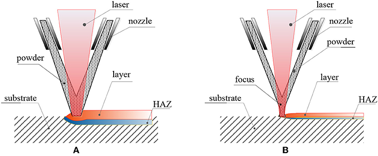
Figure 1. Schematic diagram of principle of (A) LMD and (B) EHLMD.
Hydraulic support cylinder is the main bearing part of the hydraulic support, which will be damaged in the special environment of coal mining by corrosion and wear. Preparation of chromium-enriched martensitic stainless steel layer on the cylinder surface can be used for protection and repair (Yang et al., 2013; Guo et al., 2018). Many researches have been done on martensitic stainless steel layer. Hemmati et al. (2011a) conducted microstructural characterization of AISI 431 martensitic stainless steel laser deposited layers and Liu et al. (2016) researched the influence of heat treatment on AISI 431 layer properties. However, most of the researches in this area is based on LMD, there is few published literature on extreme high-speed laser deposited martensitic stainless steel. Therefore, it is very meaningful to investigate the differences in microstructure and properties between LMD and EHLMD. In this research, AISI431 stainless steel layers were deposited on 27SiMn substrate which is used as the material of hydraulic support cylinder. The microstructure evolution and corrosion resistance were analyzed for layers prepared by LMD and EHLMD techniques. The results provide a theoretical foundation for the production and repair of shaft parts in the manufacturing field.
Experimental Procedures
Equipment and Materials
LMD system consisted of a 4 KW disc laser, a conventional lathe and robot. EHLMD system consisted of a 3 KW diode laser, a conventional lathe with CNC controller. The AISI431 stainless steel powder used in both LMD and EHLMD has the same chemical composition, but the range of particle size is different (the powder diameter of LMD and EHLMD is 50–150 and 15–53 μm, respectively). The chemical composition of powder and 27SiMn substrate are given in Table 1. The layers were fabricated on the substrate with a dimension of Φ44 × 300 mm by LMD and EHLMD. Prior to deposition, substrate surface was ground and then purged with alcohol to remove contaminants, and powders was dried for 1 h at 140°C.
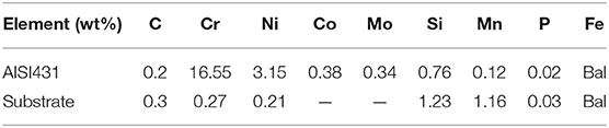
Table 1. Chemical compositions of the AISI431 powder and 27SiMn substrate.
Experiments
To study the microstructure and microhardness of layers fabricated by the two methods, single- and double-track specimens were built up on the surface of substrate. The processing parameters of the two methods were shown in Table 2. The specimens were sectioned in the transverse directions. All specimens were ground and polished depending on the standard procedures, and then etched for 20 s in a solution consisting of 3 g FeCl3, 15 ml HCl, and 100 ml H2O (Ran et al., 2018). The microstructures of the specimens were studied using RX50M optical microscopy (OM) and ZEISS Gemini scanning electron microscopy (SEM). Energy dispersive spectrometer (EDS) elemental mapping was employed to analyze the distribution and content of alloying elements. The microhardness was measured at a load of 4.9 N and a dwell time of 15 s.
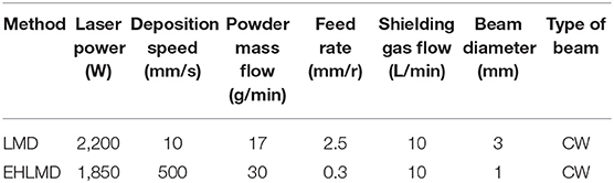
Table 2. Processing parameter for LMD and EHLMD experiments.
Single layers with an overlap of several tracks were deposited on a substrate and then ground. Subsequently, single layers were cut by wire cutting machining from the substrate and the rectangle specimens with the dimensions of 10 × 10 × 5 mm were obtained. These specimens were used to do X-ray diffraction (XRD) phase analysis and electrochemical corrosion test. Electrochemical measurements in 3.5% NaCl solutions were carried out on an electrochemical workstation at 25°C. The conventional three-electrode cell was used, the specimens as research electrode, the Ag/AgCl electrode as reference electrode, and the platinum electrode as auxiliary electrode. The polarization curves were measured from −1.0 to −0.1 V.
Results and Discussion
Deposition Efficiency and Macroscopic Feature
For the laser melting deposition on the cylinder surface, the efficiency is related to the deposition speed and feed rate of the component and can be described by the following function:
in which eff (m2/h) is the area of laser melting deposition for an hour, d (mm) is diameter of cylinder substrate, v (mm/s) is deposition speed and x (mm/r) is the feed rate (which is the distance that the laser beam moves along the axis when the cylinder substrate rotates a circle). According to Table 2, it can be calculated that the efficiency of LMD is 0.09 m2/h, and the efficiency of EHLMD is 6 times higher than that of LMD, reaching 0.54 m2/h.
Figure 2 shows the surface morphology of LMD single layer, EHLMD single layer, and polished EHLMD layer which is obtained by remelting the EHLMD single layer surface with a low power laser beam and without powder injection. It is obvious that the surface roughness of EHLMD single layer is significantly better than that of the LMD layer due to high overlapping rate and the precise coordination of powder and laser beam. Laser melting deposition (LMD) layer should be ground to meet the standard of surface roughness. Considering the production efficiency and cost, the LMD layer should be turned by lathe before being processed by grinder. After the processing, the thickness of LMD layer was reduced by 0.7 mm. Owing to the smoother surface, the EHLMD layer surface can achieve the same level by grinding directly, and the layer thickness was reduced by only 0.1 mm. For some components with lower surface roughness standard and no sliding friction, the polished layer can be directly used after laser remelting, thus eliminating the grinding process.
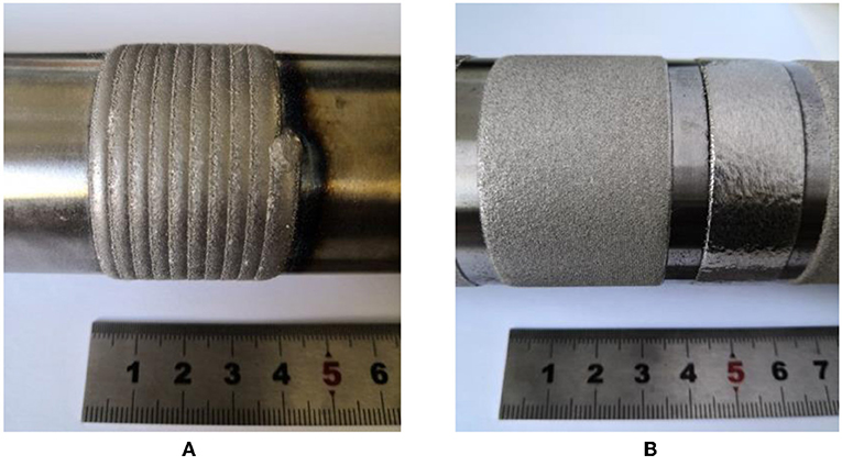
Figure 2. The surface of (A) LMD single layer; (B) EHLMD single layer and polished layer.
Microstructures of LMD and EHLMD
The microstructures of the single-track LMD layer and EHLMD layer are presented in Figure 3. Figure 3A shows the morphology of the LMD layer, the thickness, the melting depth and the width is 760, 729, and 3,490 μm, respectively. The dilution rate is 48.9%, and the range of the heat affected zone is about 615 μm. The LMD layer is mainly composed of cellular, dendrite and equiaxed crystal. Figures 3C,E,G shows the microstructure of the bottom, middle, and top of the LMD layer, respectively. At the bottom of the layer, it can be seen that cellular crystals epitaxially grow from the partially melted zone of the base metal. During the solidification, the temperature gradient at the bottom of the melting pool is large and the composition undercooling at the front of the solid-liquid interface is small, forming hexagonal cellular crystals. In the middle of the pool, a larger composition undercooling zone is formed due to the decrease of the temperature gradient. Thus, the microstructure in this area is mainly composed of dendrites growing in the opposite direction of the heat flow direction. At the top of the molten pool, the temperature gradient is the smallest and the composition undercooling area is the largest, forming equiaxed crystals.
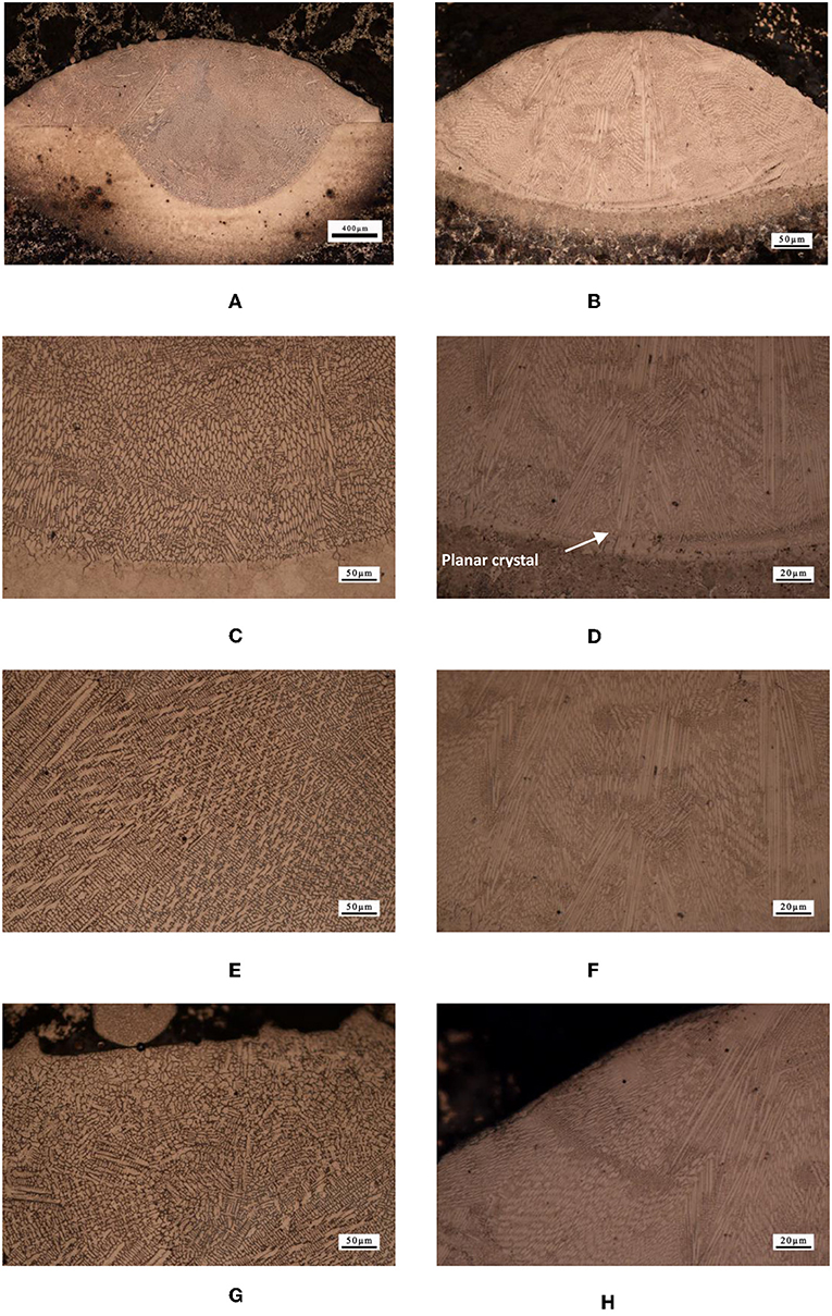
Figure 3. Microstructure of single-track layers. (A) Morphology of the LMD layer; (B) morphology of the EHLMD layer; (C) bottom of the LMD layer; (D) bottom of the EHLMD layer; (E) middle of the LMD layer; (F) middle of the EHLMD layer; (G) top of the LMD layer; (H) top of the EHLMD layer.
Figure 3B shows the morphology of the single-track EHLMD layer, the thickness, the melting depth and the width is 167, 87, and 242 μm, respectively. The dilution rate is 34.3%, and the range of the heat affected zone is about 60 μm. The microstructure of EHLMD layer is mainly composed of a large number of cellular crystals with obvious orientation and dendrites with small secondary-arm spacing. At the beginning of the solidification process, extremely high deposition speed results in a larger temperature gradient than LMD, and there is few composition undercooling near the solid-liquid interface, which promotes the growth of planar crystals (as showed in Figure 3D). As the solidification progresses, similar to that of LMD, cellular crystals appear and grow. However, because the temperature gradient in the EHLMD melting pool is larger than LMD, the composition undercooling is relatively smaller, so the microstructure of most EHLMD layer is made up of cellular crystals (shown in Figures 3F,H).
Figure 4 shows the microstructures of double-track LMD layer and EHLMD layer. It is observed that subsequent layers could re-melt part of the preceding layer in both layers. According to the overlap areas of both samples shown in Figures 4A,C. Dendrites grow perpendicularly to the curved outline of molten pool. The microstructure in the interlayer heat affected zone has the same characteristic and dimension as that inside the single-track layer, and there is no coarsening caused by reheating.
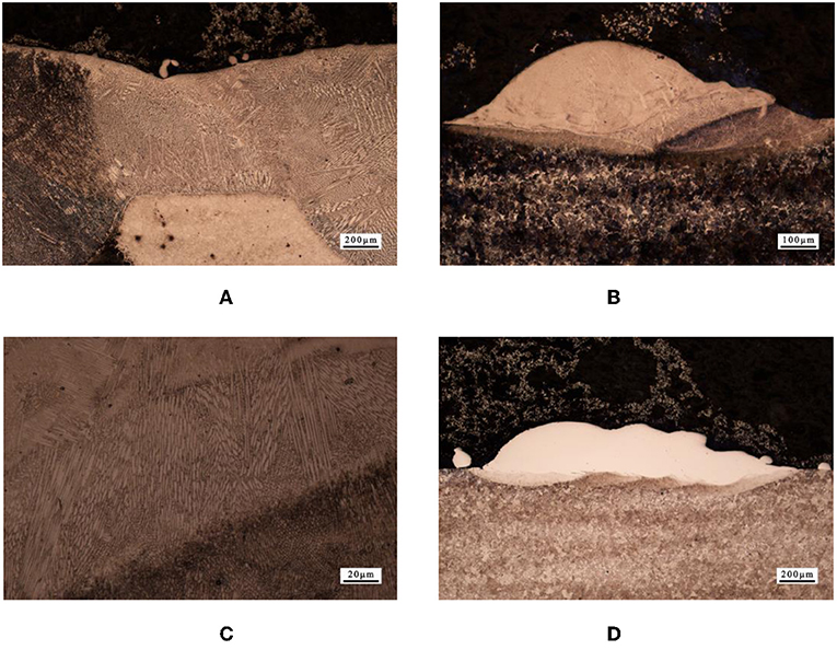
Figure 4. Microstructure of multi-track layers. (A) Overlapping area of double-track LMD layer; (B) double-track EHLMD layer; (C) overlapping area of double-track EHLMD layer; (D) four-track EHLMD layer.
Figures 4B,D show the double-track and four-track EHLMD layers. Due to the high overlap rate, part of the energy of laser beam is absorbed by the preceding track when the subsequent track is carried out, so the melting depth of subsequent track are obviously smaller than the preceding track, the dilution rate of subsequent track is <5%, and the layer thickness is directly increased to 252 μm. As the number of tracks increased, the thickness of layer gradually increased until the fourth track, the layer thickness remained stable with the thickness of 292 μm.
Figure 5 shows the microstructure of the bottom and middle parts of two kinds of layer. It can be seen that the LMD layer (Figures 5A,B) is composed of dendrites with width ranging 4–9 μm and a large number of continuous inter-dendritic eutectic phases. According to the previous investigations (Fang et al., 2017), the matrix is identified as a typical martensitic structure, whereas the eutectic phases were clearly identified as M23C6 and M7C3 carbides. Similar to LMD layer, the EHLMD layer (Figures 5C,D) is composed of cellular crystals with width ranging 1.0–1.5 μm and a large number of continuous inter-dendritic eutectic phases.
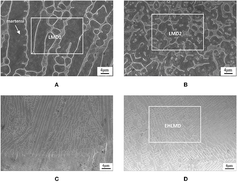
Figure 5. SEM of LMD and EHLMD layer. (A) Bottom of LMD layer; (B) middle of LMD layer. (C) Bottom of EHLMD layer; (D) middle of EHLMD layer.
Studying the solute distribution by EDS mapping (Figure 6), the results show that there are different distribution characteristics in LMD and EHLMD layers. There is detectable element segregation in LMD layer, whereas the segregation is not observed in EHLMD layer. According to the previous analysis (Hemmati et al., 2011b), the higher cooling rate of EHLMD obviously refines the grain size and decreases the spacing of secondary diameter arms, so the concentration of solute and the tendency of forming element segregation are lower, and the element distribution in EHLMD layer is more uniform than that in LMD layer.
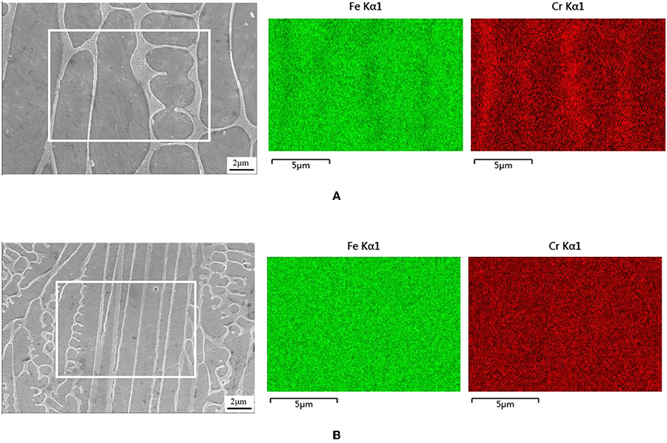
Figure 6. EDS spectral mapping of (A) LMD layer; (B) EHLMD layer.
Phase and Microhardness
XRD tests were performed on the surface of the two kinds of layers after grinding to confirm the phase composition and content. The results shown in Figure 7 reveal that the main phases of two kinds of layers are α-(Fe, Cr) and γ-Fe. The retained austenite are obtained under rapid cooling. In LMD and EHLMD layers, α-(Fe,Cr) content is 88.5 and 79.75%, while γ-Fe content is 11.5 and 20.25%, respectively.
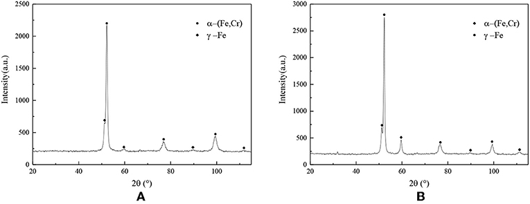
Figure 7. XRD patterns of (A) LMD layer; (B) EHLMD layer.
The reason why retained austenite content in EHLMD layer is more than LMD layer is that the EHLMD cooling rate is faster, which leads to the decrease of grain size. According to the model proposed by Jiang et al. (1995), the Ms (martensite start temperature) is relate to the grain size of austenite matrix and can be described as the following function:
in which Msc is the martensite start temperature calculated based on alloy composition, B is a constant related to material and not very sensitive to compositional changes, D is the value of austenite grain size. In a coarse grain austenitic structure, the martensite start temperature (Msc) primarily depends on the chemical composition but in a fine grain austenitic structure, the extra barrier caused by increased yield strength of material as given by the Hall—Petch relationship requires greater driving force which results in a lower Ms temperature (Liu et al., 2016). Only the continuous cooling, the undercooled austenite will continue to be transformed into martensite, so the martensite content of EHLMD is less than LMD at room temperature.
The microhardness of layers fabricated by the two methods is indicated in Figure 8. The microhardness of the layers fabricated by the two methods are comparable, within the 600–720 HV range, which is mainly due to the finer grains of EHLMD layer that the resulting fine grain strengthening makes up for the microhardness reduction caused by less martensite. In the process of LMD and EHLMD, the substrate in HAZ undergoes rapid heating and cooling. The peak temperature of HAZ near the fusion line is the highest, the microstructure is mainly martensite, and the microhardness is significantly higher than that of the substrate. With the increase of the distance from the fusion line, the peak temperature decreases gradually and the martensite content decreases. The microstructure of HAZ is mainly composed of massive ferrite, pearlite and a small amount of bainite, the microhardness decreases gradually until it is the same as the microhardness of the substrate (Shi et al., 2017). Compared with LMD, the HAZ of EHLMD is smaller because of its lower linear energy. However, the microhardness of LMD and EHLMD in the HAZ has the same trend.
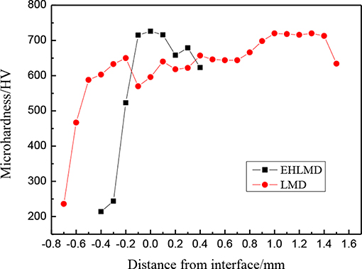
Figure 8. Microhardness distribution of two kinds of deposition layers.
Electrochemical Corrosion Resistance
Figure 9 shows the polarization curves of EHLMD layer, LMD layer and substrate. Usually corrosion current density and self-corrosion potential are considered to be important parameters to evaluate the corrosion resistance of materials, in which the corrosion current density determines the corrosion rate of the material, the lower the current density, the slower the corrosion rate of the material. The corrosion potential, which is the potential value of the curve when the corrosion current is minimum, reflects the corrosion trend of the material, the larger the value is, the less likely the material is to be corroded (Sanchez-Tovar et al., 2013; Feng et al., 2019). According to Figure 9, the corrosion current of LMD layer is lower than that of EHLMD layer, indicating that the corrosion speed of LMD layer is slower. However, the corrosion potential of EHLMD layer is highest, which indicates that EHLMD is least susceptible to corrosion in solution.
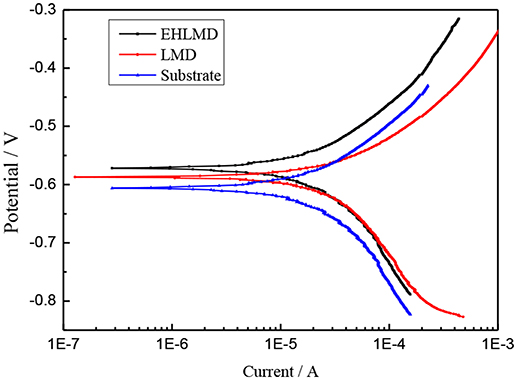
Figure 9. Polarization curves of LMD, EHLMD, and substrate.
Table 3 shows the chemical composition of the middle part of the LMD (shown in Figures 5A,B) and EHLMD (shown in Figure 5D) layers obtained by EDS test, Cr and Ni content of EHLMD is higher than the LMD because of the lower dilution rate of EHLMD. The corrosion potential can be significantly improved with increasing content of Cr and Ni that EHLMD layer corrosion resistance is superior to the LMD layer. In addition, due to the slow cooling rate of LMD, it is more likely for C and Cr to form carbide at the grain boundary at high temperature, which weakens the beneficial effect of Cr element on corrosion resistance. Because of faster cooling speed, the EHLMD layer has finer grains and more uniform alloying elements distribution. Therefore, electrochemical corrosion resistance of EHLMD layer is higher than that of LMD layer.
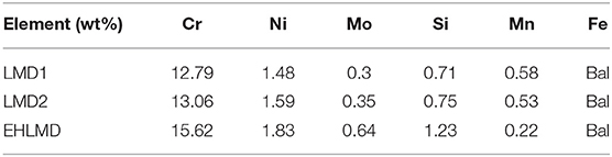
Table 3. Chemical composition of different areas of the two kinds of layers.
Conclusions
Cr-enriched stainless steel layers formed by LMD and EHLMD have been compared. Initially, single-, double- track and single layers have been deposited with different methods. Then, microhardness and phase analysis have been conducted. After that, the microstructure produced by two kinds of methods have been compared. Finally, in order to identify the corrosion resistance of the two cladding layers, polarization curves have been characterized. Based on the above research, main conclusions could be achieved as follows.
1. The efficiency of LMD is 0.09 m2/h, while that of EHLMD is 0.54 m2/h, which promotes the production efficiency by 6 times. Considering that the subsequent processing of EHLMD is simpler, the actual production efficiency could be further improved.
2. Both the LMD and EHLMD layers are composed of martensite and retained austenite. The retained austenite content of EHLMD layer is higher than that of LMD, but the microhardnesses of the two layers are basically the same, in the ranging from 600 to 720 HV.
3. The dilution rate and the heat affected zone range of the EHLMD are obviously smaller than that of the LMD. For EHLMD, the sum depth of the melting pool and heat affected zone is 80 μm, while for LMD, the sum depth of the melting pool and heat affected zone is 1,344 μm. The influence depth of LMD on substrate is 16 times than that of EHLMD.
4. Because of higher Cr content caused by the lower dilution rate, the corrosion resistance of EHLMD layer is higher than that of LMD.
Data Availability Statement
All datasets generated for this study are included in the manuscript/supplementary files.
Author Contributions
BD, MW, and BS: conception and design of study. NX, YX, and SH: acquisition of data. BD, BS, NX, and YX: analysis and interpretation of data. BS and BD: drafting the manuscript. BD and NX: revising the manuscript critically for important intellectual content. All authors certify that they have participated sufficiently in this work to take public responsibility for the content, including participation in the followed concept.
Funding
This research was financially supported by the Natural key R&D Program of China (Grant No. 2016YFE0206000).
Conflict of Interest
All authors were employed by company Beijing National Innovation Institute of Lightweight Ltd.
References
Dai, D., Gu, D., Xia, M., Ma, C., Chen, H., Zhao, T., et al. (2018). Melt spreading behavior, microstructure evolution and wear resistance of selective laser melting additive manufactured AlN/AlSi10Mg nanocomposite. Surf. Coatings Technol. 349, 279–288. doi: 10.1016/j.surfcoat.2018.05.072
Dworak, A., Sienicki, J., Koruba, P., and Jurewicz, P. (2018). Application of Ultra-High-speed Laser Cladding for functional coatings deposition in aviation industry. Przeglad Spawalnictwa. 89, 15–19. Available online at: https://vtol.org/store/product/application-of-ultra-high-speed-laser-cladding-technology-for-functional-coatings-deposition-12807.cfm
Fang, J. X., Dong, S. Y., Wang, Y. J., Xu, B. S., Zhang, Z. H., Xia, D., et al. (2017). Microstructure and properties of an as-deposited and heat treated martensitic stainless steel fabricated by direct laser deposition. J. Manuf. Proces. 25, 402–410 doi: 10.1016/j.jmapro.2016.12.014
Feng, X., Gu, H., Zhou, S., and Lei, J. (2019). Microstructure and electrochemical corrosion behavior of TC4 titanium alloy cladding layer prepared with powder feeding laser additive manufacturing. Chin. J. Laser. 46:0302003. doi: 10.3788/CJL201946.0302003
Guo, W., Li, K., Chai, R., Zhang, L., and Zhang, C. (2018). Analysis of microstructure and wear resistance of Fe-based alloy on 27SiMn steel surface by laser cladding. Appl. Laser. 38, 351–357. doi: 10.14128/j.cnki.al.20183803.351
Hemmati, I., Ocelik, V., and De Hosson, J. T. M. (2011a). Microstructural characterization of AISI 431 martensitic stainless steel laser-deposited coatings[J]. J. Mater. Sci. 46, 3405–3414. doi: 10.1007/s10853-010-5229-2
Hemmati, I., Ocelík, V., and De Hosson, J. T. M. (2011b). The effect of cladding speed on phase constitution and properties of AISI 431 stainless steel laser deposited coatings[J]. Surf. Coat. Technol. 205, 5235–5239. doi: 10.1016/j.surfcoat.2011.05.035
Jiang, B. H., Sun, L., Li, R., and Hsu, T. Y. (1995). Influence of austenite grain size on {gamma}-{var_epsilon} martensitic transformation temperature in Fe-Mn-Si alloys. Scripta Metal. Mater. 33, 63–68. doi: 10.1016/0956-716X(95)00081-6
Li, J., Li, Y., Tian, X., Tian, X., Zou, L., Zhao, X., et al. (2017). The hardness and corrosion properties of trivalent chromium hard chromium. Mater. Sci. Appl. 08, 1014–1026. doi: 10.4236/msa.2017.813074
Liu, Y., Li, A., Cheng, X., Zhang, S. Q., and Wang, H. M. (2016). Effects of heat treatment on microstructure and tensile properties of laser melting deposited AISI 431 martensitic stainless steel. Mater. Sci. Eng. A 666, 27–33. doi: 10.1016/j.msea.2016.04.014
Paydas, H., Mertens, A., Carrus, R., Lecomte-Beckersa, J., and Tchoufang Tchuindjang, J. (2015). Laser Cladding as repair technology for Ti-6Al-4V alloy: influence of buiding strategy on microstructure and hardness. Meter. Design 85, 497–510 doi: 10.1016/j.matdes.2015.07.035
Ran, C., Yanhai, C., Xianliang, M., Shiezhe, F., and Zhengtong, H. (2018). Microstructure and properties of heat treated 1Cr17Ni4MoB steel fabricated by laser melting deposition. Optics Laser Technol. 108, 59–68 doi: 10.1016/j.optlastec.2018.06.045
Sanchez-Tovar, R., Montanes, M.T, and Garcia-Anton, J. (2013). Contribution of the flowing conditions to the galvanic corrosion of the copper/AISI 316L coupling in highly concentrated LiBr solution. Corrodion Sci. 68, 91–100. doi: 10.1016/j.corsci.2012.10.039
Schopphoven, T., Gasser, A., and Backes, G. (2017). EHLA: extreme high-speed laser material deposition: economical and effective protection against corrosion and wear. Laser Technik J. 14, 26–29. doi: 10.1002/latj.201700020
Schopphoven, T., Gasser, A., and Wissenbach, K. (2016). Investigations on ultra-high-speed laser material deposition as alternative for hard chrome plating and thermal spraying. J. Laser Appl. 28:022501. doi: 10.2351/1.4943910
Shi, P., Huang, J., Tantai, F., and Yao, C. (2017). Microstructures and properties of 27SiMn high-strength steel joints by laser-MAG hybrid welding. Chin. J. Lasers. 44, 58–64. doi: 10.3788/CJL201744.1002001
Sienicki, J., Zorawski, W., Dworak, A., Koruba, P., Jurewicz, P., Reiner, J., et al. (2019). Cold spraying and laser cladding as an alternative to electroplating processes. Aircraft Eng. Aerospace Technol. 91, 205–215. doi: 10.1108/AEAT-01-2018-0071
Wang, K., Chang, B., Chen, J., and Fu, H. (2017). Effect of molybdenum on the microstructures and properties of stainless steel coatings by laser cladding. Appl. Sci. 7:1065. doi: 10.3390/app7101065
Wang, K., Du, D., Liu, G., Chang, B., and Hong, Y. (2019). Microstructure and properties of WC reinforced Ni-based composite coatings with Y2O3 addition on titanium alloy by laser cladding. Sci. Technol. Weld. Join. 24, 1–8. doi: 10.1080/13621718.2019.1580441
Wang, Y. D., Tang, H. B., Fang, Y. L., and Wang, H. M. (2010). Effect of heat treatment on microstructure and mechanical properties of laser melting deposited 1Cr12Ni2WMoVNb steel. Mater. Sci. Eng. A 528, 474–479. doi: 10.1016/j.msea.2010.09.038
Yang, Q., Su, L., Dong, C., Du, X., Yang, F., and Zhang, L. (2013). Properties of Fe-based alloy cladding layers on hydraulic support column steel 27SiMn. China Surf. Eng. 26, 42–47. doi: 10.3969/j.issn.1007-9289.2013.06.007
Zhong, C., Gasser, A., Kittel, J., Wissenbach, K., and Poprawea, R. (2016). Improvement of material performance of Inconel 718 formed by high deposition-rate laser metal deposition[J]. Mater. Design 98, 128–134. doi: 10.1016/j.matdes.2016.03.006
Keywords: laser melting deposition, extreme high-speed, martensitic stainless steel, microstructure, electrochemical corrosion resistance
Citation: Shen B, Du B, Wang M, Xiao N, Xu Y and Hao S (2019) Comparison on Microstructure and Properties of Stainless Steel Layer Formed by Extreme High-Speed and Conventional Laser Melting Deposition. Front. Mater. 6:248. doi: 10.3389/fmats.2019.00248
Received: 27 May 2019; Accepted: 19 September 2019;
Published: 02 October 2019.
Edited by:
Hanguang Fu, Beijing University of Technology, ChinaReviewed by:
Ying Hua Lin, Putian University, ChinaTianle Xie, Hunan University, China
Jianjun Zhang, Xihua University, China
Qi Wang, Huanghuai University, China
Copyright © 2019 Shen, Du, Wang, Xiao, Xu and Hao. This is an open-access article distributed under the terms of the Creative Commons Attribution License (CC BY). The use, distribution or reproduction in other forums is permitted, provided the original author(s) and the copyright owner(s) are credited and that the original publication in this journal is cited, in accordance with accepted academic practice. No use, distribution or reproduction is permitted which does not comply with these terms.
*Correspondence: Miaohui Wang, d2FuZ21oMDEwM0AxNjMuY29t