 Fernando Cotting
 André Koebsch2
 Idalina Vieira Aoki
- 1Corrosion and Surface Engineering Laboratory, Chemical Engineering Department, Federal University of Minas Gerais, Belo Horizonte, Brazil
- 2Petrobras–Cenpes, Rio de Janeiro, Brazil
- 3Polytechnic School of the University of São Paulo, São Paulo, Brazil
In this work, poly (urea-formaldehyde-melamine) (PUFM) microcapsules containing a commercial epoxy ester resin were synthesized by in-situ polymerization technique. The microcapsules size distribution was analyzed by laser diffraction, and the obtained microcapsules were evaluated by the Fourier-transform infrared spectroscopy (FTIR-ATR) to prove the ester epoxy resin microencapsulation. The filled microcapsules were incorporated into an epoxy three-layer coating system, varying the microcapsules concentration (10 and 15%) and the microcapsules incorporation on the different layers—first, second, or both. The coatings electrochemical behavior was evaluated by electrochemical impedance spectroscopy (EIS) technique and localized scanning vibrating electrode technique (SVET). Pull-off adhesion tests were performed in the coatings systems, to verify if the microcapsules presence affect the adhesion and/or cohesion coating properties. The EIS results showed that microcapsules change the coating electrochemical response, but the samples visual aspect suggests that the microcapsules improve the barrier properties of the microcapsules systems. The coating system containing the microcapsules showed a significant self-healing effect when stressed by a mechanical defect and the higher concentration (15 wt. %) of microcapsules provided a better self-healing protection, with better anticorrosive performance. Additionally, the microcapsules did not disturb the adhesion/cohesion properties of the coating system.
Introduction
The use of coatings is the most popular corrosion protection method, to protect metallic surfaces against aggressive species. Corrosion process implies significant costs mainly due to the need for a protection method to be applied (NACE International, 2016). Even employing the best protective technology, maintenance is mandatory to extend the useful life of metallic structures in all industrial practices. If some technology can diminish the frequency of repairing interferences, the economic gains would be substantial.
In this way, in the last 20 years, there are a growing number of researches in the self-healing coatings theme. Among the different strategy to develop a self-healing coating, the directly incorporation of polymeric microcapsules in the coating matrix is the best one. The polymeric microcapsules are synthesized to entrap in their core a film former or a corrosion inhibitor, so when they are incorporated in the coating they act as recovery material storage. Therefore, after a mechanical defect the microcapsules are broken and release the content of their core in the defect site, providing the formation of a polymeric film or allowing the released corrosion inhibitor to act in the damaged area (Montemor, 2014; Bekas et al., 2016; Cotting and Aoki, 2016).
Among many possible film formers like cyclopentadiene (White et al., 2001), linseed oil (Adamczak et al., 2013; Siva and Sathiyanarayanan, 2015; Vakhitov et al., 2017), Tung oil (Cailleux and Pollet, 2009; Samadzadeh et al., 2011; Fayyad et al., 2015; Singh et al., 2015), silanes (Montemor et al., 2009; Cotting and Aoki, 2016), and epoxy bi-component (Liu et al., 2015; Ebrahiminiya et al., 2018), or polyurethane (Huang and Yang, 2011). The alkyd healing systems are more advantageous than other systems; because they do not need catalysis for the polymerization reaction, making them autonomous systems. Otherwise, the alkyd coatings have low anti-corrosive and barrier properties than epoxy systems (Tracton, 2007; Singh et al., 2015).
The epoxy ester resin is a hybrid resin, which is synthesized from epoxy resins and fatty acids. Epoxy ester resins are synthesized from the esterification reaction between an epoxy resin and a fatty acid in the presence of p-toluene sulfonic acid (p-TSA). The epoxy resin used is the resin synthesized from Bisphenol A and the fatty acid used comes from vegetable oils. The most commonly used vegetable oils for the synthesis of epoxy ester resins are linseed oil, soybean oil, castor oil and Tung oil. This approach makes these resins have hybrid characteristics because they have a more crosslinked polymer network due to the epoxy groups and the curing is done at room temperature due to the oxidative polymerization of the unsaturation's present in the epoxy ester resin (Singh et al., 2015). Also, the epoxy ester self-healing systems have not been explored (Zhang et al., 2018).
Therefore, the main goal of this paper is to present the encapsulation of an epoxy ester resin in poly (urea-formaldehyde-melamine) walled microcapsules and their effective incorporation in an epoxy coating system, obtaining a self-healing coating. Scanning electron microscopy (SEM) and FTIR-ATR techniques were employed to morphological and chemical characterization. Electrochemical methods, such as EIS (electrochemical impedance spectroscopy) and SVET (scanning vibrating electrode technique) were used for self-healing effect evaluation. Pull-off strength test was also provided to verify the microcapsules influence on the cohesion and adhesion properties.
Experimental
Surface Treatment
The carbon steel specimens were blasted with carbon steel grit G-25 till a roughness profile of 60–70 μm and after blast step; the samples were cleaned with dry airflow. Before coating application, the carbon steel samples were cleaned with acetone, ethanol and finally dried with hot airflow.
Microcapsules Synthesis
Microcapsules were obtained by the in situ polymerization method. The procedure adopted was similar to Patent WO2014032130A1 (Petrobras et al., 2012). Therefore, 250 g of water, 20 g of an epoxy ester resin, 2.5 g of urea, 3.5 g of sodium chloride, 0.25 g of ammonium chloride, 0.25 g of resorcinol, 2 g of Arabic gum and 0.25 of melamine were added into a 350 ml Becker. The agitation was added to the system with Ika® Ultra-turrax T-25 disperser, adjusting the rotation in 5,000 RPM. After 60 min, the pH was adjusted with a 10% HCl solution to 3.5 and 6.4 g formaldehyde was added to the reaction vessel. So, the agitation was slowed to 250 RPM to avoid the evaporation of the ester epoxy resin solvents during the wall of microcapsules formation, the reaction temperature was controlled in three steps 1 h at 45°C, 2 h at 50°C, and finally 1 h at 55°C. Vacuum filtration permits the separation of the microcapsules that are allowed to dry at room conditions for 12 h. A free-flowing powder was obtained.
The following methodology was performed to determine the amount of encapsulated resin in the microcapsules. A 1.0 g sample of microcapsules was macerated in a mortar, in the presence of 5 ml dichloromethane. After the maceration process, the material was subjected to an ultrasonic bath for 5 min and then vacuum filtered. The material retained on the filter paper was again washed with the organic solvent, macerated and filtered again to ensure full extraction of the encapsulated material from the sample.
The filtered solution—solvent and encapsulated material—and the material retained on the filter paper—polymer—were placed in an oven at 60°C for 48 h. After this step, the filtered material and the retained material were weighed so that the fraction of encapsulated material and the polymer fraction in each sample could be determined. The percentage of encapsulated material present in the sample was determined by Equation (1).
This procedure was performed in triplicate.
Microcapsules Incorporation in an Epoxy Coating and Application on Carbon Steel Panels
The microcapsules were added to a surface tolerant epoxy coating with 97% of solids in 10 and 15 wt. % ratios. Three-layer coating system was applied, with around 200 μm thick each one. Besides that, different colors were adopted for each coating layer, in order to assist the pull-off test assessment. Figure 1 shows the coating scheme employed.
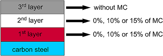
Figure 1. Coating scheme representation.
Table 1 shows all the conditions and respective codes for the microcapsules samples. Letter E denotes the epoxy ester resin. Three numbers denote the three layers of the coating system and 100/10C means that the microcapsules were added only in the first layer (primer) in 10% ratio; 120/15C denotes that microcapsules were added in the first and also in the second layer in 15 wt. % ratio, and so on. Finally, the layers with microcapsules have the letter C in their code and the layers that do not have microcapsules have the letters SC, indicating the absence of this pigment.
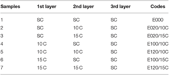
Table 1. Composition of different coating layers, with or without microcapsules, on carbon steel, and their respective codes.
EIS Measurements
The EIS measurements were performed in a three-electrode electrochemical cell using an Ag/AgCl (sat KCl) reference electrode, a platinum counter electrode with an exposed area of 12 cm2 and the working electrode being the coated steel panel with an exposed area of 6.26 cm2. The area was delimited by attaching a glass tube, with neutral curing silicone adhesive to the coated specimens. In the EIS measurements, the employed electrolyte was 0.1 mol/L NaCl aqueous solution.
As the real exposed area of the metal to the electrolyte is absolutely significant for the EIS results, it is very critical to perform reproducible defects in order to achieve confident results. In this sense, EIS measurements were performed in coated panels with and without a provoked defect. In the absence of the defect, the objective was to verify if the presence of the microcapsules were disturbing the performance of the painting system. For the conditions with a provoked defect, it was possible to evaluate the self-healing ability of the microcapsule-containing samples. In order to guarantee the reproducibility of the 200 μm diameter defects, these were performed with a manual micro-drill. The immersion tests for the EIS evaluation were performed 14 days after the last layer of coating was applied to the specimens to assure the complete cure of the epoxy coating.
The frequency range analyzed in the samples without defect was 100 kHz to 10 mHz; with a sinusoidal perturbation of 20 mV rms at open circuit potential (OCP) and 10 measurements were acquired per decade of frequency. For damaged samples, the frequency range used was from 50 kHz to 5 mHz, employing a sinusoidal perturbation of 10 mV rms at OCP and 10 measurements were also acquired per frequency decade. The damaged samples were exposed to room air for 48 h after the defect was made to permit there was time to cure and reticulate the epoxy ester resin released from the core of the microcapsule by contact with the oxygen in the air. For the defect samples, EIS measurements were performed after 6, 24, and 48 h of immersion in the electrolyte. The intact samples were evaluated up to 28 days of immersion.
SVET Measurements
The SVET tests were carried out using Applicable Electronics equipment controlled by ASET-Sciencewares software. Data were treated by Quikgrid software version 5.4. The vibrating probe was a MicroProbe platinum/iridium microelectrode containing a platinum deposit at the tip whose diameter was ~10 μm. The use of the local technique was intended to assess the activity in a provoked defect region on coated samples, for with microcapsules or without microcapsules conditions. A defect of 3 mm length was made with a blade. After provoking the defects, the samples were allowed to stay in the laboratory atmosphere for 48 h before the SVET measurements have been performed. This time is sufficient to promote the polymerization by air O2 in order to obtain a protective film in the defect region. For SVET measurements only one layer of 200 μm thickness were applied because for a complete system of about 600 μm thick, it would be impossible to detect ionic currents coming from such long distance in defect area. In such terms, only three conditions have been evaluated: (1) without microcapsules; (2) with 10 wt. % of microcapsules; and (3) with 15 wt. % of microcapsules. A 0.01 mol/L NaCl solution was used during the SVET measurements.
Pull off Adhesion Test of Coated Samples
Pull-off adhesion measurements were performed 21 days after application of the last layer of coating on the specimens to ensure complete cure of coating. Using PATTI Quantum digital equipment, measurements were taken at three points of each panel. The piston used in the tests was the F-8 and the stubs were 2.54 cm in diameter. The adhesive used was the J-B Weld bi-component epoxy adhesive. The tests were performed and discussed according to ASTM D4541-17.
Aspect and Size of Microcapsules
A TESCAN Vega 3 scanning electron microscope (SEM) was used to register the aspect of the obtained microcapsules. The cumulative numeric size distribution of the microcapsules was obtained by laser diffraction using a model 3000 Mastersizer from Malvern.
FTIR-ATR Analysis of the Entire and Crushed Microcapsules
The microcapsules containing the epoxy resin were characterized by the FTIR-ATR technique. FTIR-ATR analyses were performed on a Nicolet brand 6700 model with diamond crystal. Spectra were obtained in the region of 0–4,000 cm−1. Samples of intact microcapsules, ruptured microcapsules and pure epoxy resin were analyzed, thus verifying if microencapsulation was performed successfully.
Salt Spray Chamber Exposition
The salt spray chamber exposition was performed in a fog chamber according to the ASTM standard B-117. The coatings were damaged with a blade with 0.7 mm width, creating a horizontal scribe with ~8 cm. Only the original coating—no microcapsules—and the self-healing coating containing 15% of microcapsules in the first and second layer were submitted to salt spray chamber test. The samples were exposed for 720 h.
All experiments were performed in triplicate.
Results
SEM Images of the Obtained Microcapsules
Figure 2 shows the SEM images of the microcapsules produced containing the epoxy ester resin. The analysis of the images allows verifying that the obtained microcapsules have a wide distribution of size, where there is a population of microcapsules of smaller size, around 10 μm and another population of larger size, with diameters in the order of 60–70 μm.
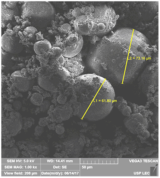
Figure 2. SEM images obtained from poly (urea-formaldehyde-melamine) microcapsules containing the epoxy ester resin.
Microcapsules Size Distribution
Figure 3 shows the histogram of the numerical distribution and the curve of the accumulated value obtained by analyzing the sample of microcapsules containing the epoxy ester resin. The analysis by the numerical distribution of the sample helps in the understanding of what was observed by the microscopic techniques (Sánchez-Silva et al., 2011), where a large number of microcapsules with diameters below 30 μm were observed and only the presence of some microcapsules with diameters around 75 μm was detected.
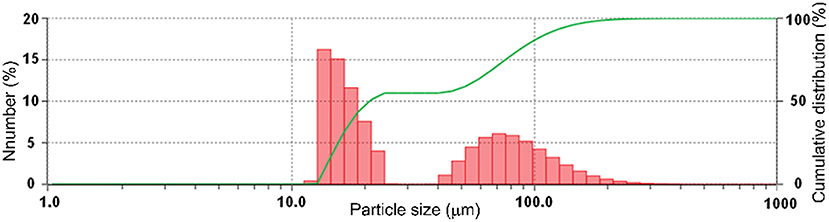
Figure 3. Histogram of the numerical distribution and cumulative value curve of poly (urea-formaldehyde-melamine) microcapsules containing the epoxy ester resin.
The treatment of the data acquired by determining the numerical distribution enabled the determination of the numerical diameters Dn10, Dn50, and Dn90, which are presented in Table 2. These values show that 10% of the total number of microcapsules has size <14 μm, 50% of the number of microcapsules has to size <21 μm and 90% of the microcapsules have to size <110 μm.
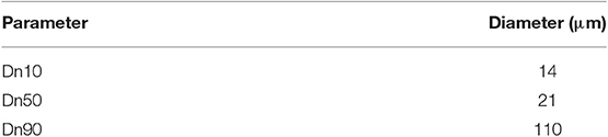
Table 2. Numeric diameters Dn10, Dn50, and Dn 90 obtained for poly(urea-formaldehyde-melamine) microcapsules containing in their core an epoxy ester resin.
The values presented by the numerical distribution are more consistent with what was observed by the images obtained with SEM, where a larger amount of microcapsules with diameters up to 30 μm was observed.
FTIR-ATR Results From Pure Resin and Entire and Crushed Microcapsules
The microcapsules were chemically characterized, to ascertain whether the released material was, in fact, the epoxy ester resin. Figure 4 shows the spectra obtained by the FTIR-ATR technique during the characterization of the poly (urea-formaldehyde-melamine) microcapsules containing the epoxy ester resin and Table 3 shows the main characteristic absorption bands of the functional groups present on the epoxy ester resin and in the poly (urea-formaldehyde-melamine) polymer.
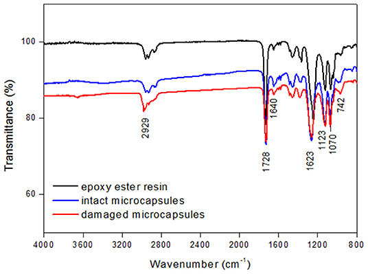
Figure 4. FTIR-ATR spectra obtained for the epoxy ester resin prior to the microencapsulation process, for the intact microcapsules containing the resin and for the broken microcapsules containing the epoxy ester resin.
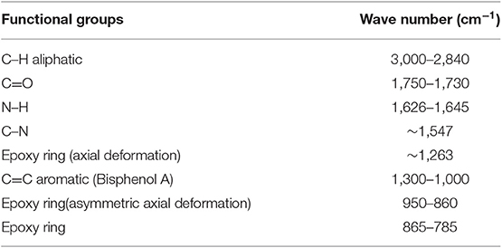
Table 3. Characteristic absorption bands and the related functional groups present in the epoxy ester resin and in the poly(urea-formaldehyde-melamine) walls of the microcapsules are shown (Chike et al., 1993; Vašková and Křsálek, 2011; Knop et al., 2014; Singh et al., 2015; Khorasani et al., 2017).
The epoxy ester resin, as its name suggests, exhibits in its structure the ester and epoxy functional groups, which in turn have characteristic absorptions in the infrared region of the spectrum. Therefore, we can identify by the spectrum of the resin (black spectrum) in Figure 4 the presence of bands, in a total of three, that are characteristic of the epoxy group. The first band in the region of ~1,263 cm−1 corresponds to the symmetrical axial deformation of the epoxy ring, which occurs by the expansion and contraction of all ring bonds. The second band, around 966 cm−1, can be attributed to the asymmetric axial deformation of the ring, where contraction of C–O type bonds and expansion in C–C type bonds occurs. The third and last band characteristic of the epoxy function, located at ~742 cm−1, corresponds to the symmetric deformation in the plane of the C–O–C bond. The presence of the ester functional group on the resin can be visualized by the presence of the band at ~1,728 cm−1, which is characteristic of the C=O bond.
In Figure 4, the spectrum presented for the intact microcapsules shows bands characteristic of the epoxy ester resin, which proves that the healing agent was microencapsulated. There is also a peak in the ~1,640 cm−1 region, which is attributed to the stretching of the N–H bonds present in the compounds constituting the polymeric wall of the microcapsules.
The gravimetric assays showed that microcapsules contain 86 ± 4 wt. % of encapsulating resin. This value is similar to studies where linseed oil and Tung oil were encapsulated.
EIS Results for Samples Without Defect
The impedance diagrams were obtained after 6 h, 7 and 28 days of immersion in the electrolyte of the coated samples without defect. Figure 5 shows the EIS diagrams obtained for the different microcapsules conditions under study and the condition without any microcapsules. The EIS diagrams show that the presence of the self-healing particles in the coating system affected the anticorrosive barrier properties. Comparing the samples containing microcapsules with the sample without microcapsules, it is observed the decay of an order of magnitude in impedance modulus values in the low-frequency region for the microcapsules samples. The traditional coating—without microcapsules—presented values around 1.88 × 10⁹ ohm·cm2, whereas the self-repairing coatings presented values in the range 8.63 × 10⁷–1.99 × 10⁸ ohm·cm2, after 6 h of immersion.
Figure 5. EIS diagrams for the coating systems without and with different wt. % of microcapsules containing epoxy ester resin, without a provoked defect, after immersion for 6 h, 7 and 28 days in 0.1 mol/L NaCl.
This perturbation of the microcapsules in the coating systems is probably related to the presence of microcapsules larger than 20 μm (the average diameter is around 30 μm) that normally causes a decrease in the barrier properties of any coating creating some preferential pathways for the electrolyte inside the coating. The lowest impedance modulus values were obtained for the highest percentage of microcapsules (15 wt. %) added in the coating and also when they were added only in the second layer.
The analysis of Bode (phase angle × log f) diagrams allows identifying a well-defined time constant in the HF region for all samples, which is related to the barrier protection properties of the coating. The presence of a single time constant, with high phase angle values and covering a large range of frequencies shows that the evaluated coating regions have no defects, making it impossible to sense the metal/electrolyte interface reactions. For the evaluation of the degradation over time of these systems by the EIS technique, it is verified that after 48 h of immersion the magnitude of decay in the impedance modulus was the same for all samples, showing that the barrier property was not affected and only the dielectric properties of the coating were altered by the microcapsules. This behavior indicates that the microcapsules affected the dielectric properties of the coating, but were not able to create effective preferential paths for the contact of the electrolyte with the substrate. However, it can be observed in the set of microcapsules samples that the systems containing the microcapsules in the first and second layers (E120), as well as the systems containing the microcapsules only in the second layer (E020), showed the more significant degradation after 48 h of immersion. These results indicate that the addition of the microcapsules in the second layer of the coating system is not the best option. This way, the best strategy to incorporate the microcapsules in the presented coating scheme is only in the first layer of the coating system, whether with 10 or 15 wt. % on the coating solids.
EIS Results for Damaged Samples
To evaluate the self-healing effect of the different coating systems, the impedance spectra were obtained after 6, 24, and 48 h of immersion in the electrolyte. Figure 6 shows the EIS diagrams of the coating systems in the different microcapsules conditions. For a better discussion of the self-healing effect, the EIS diagrams of the non-damaged coating systems E000 and E100_10C were also joined. The sample E100_10C without defect was chosen, because it presented the best anticorrosive performance, in the first hours of immersion, among the microcapsules samples.
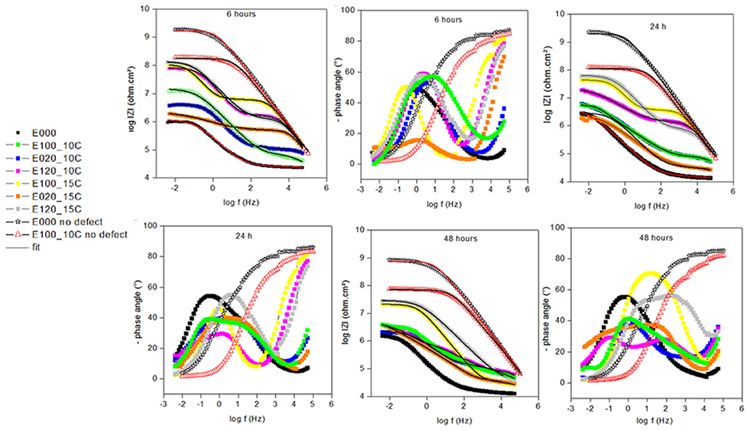
Figure 6. EIS diagrams for the coating systems without and with different pigment conditions with microcapsules containing epoxy ester resin, with a provoked defect, after immersion for 6, 24, and 48 h in 0.1 mol/L NaCl.
Based on the electrochemical behavior of the samples after 6 h of immersion, one can verify in the Bode log |Z| × log f diagrams that all the containing microcapsules and damaged samples presented impedance modulus values in LF region larger than the coating system without microcapsules and with defect (the negative reference). The higher total impedance presented for the microcapsules samples is associated with the formation of a protective film in the region of the defect by the encapsulated epoxy ester resin released after the defect execution, promoting the self-healing effect. However, the degree of self-healing promoted by each microcapsules system was influenced by the incorporation conditions.
The coating systems added only in the second layer (E020) were the systems that presented the lowest self-healing performance, because the healing agent released during the execution of the defect is at a distance of ~200 μm (average thickness of the first layer) from the carbon steel surface. Also, the samples containing microcapsules only in the first layer showed that the best self-healing performance mainly by the system with the highest microcapsules concentration (E100_15C), most likely due to the higher amount of microcapsules available in the damaged region. The samples pigmented in the first two layers of coating system (E120) presented a very similar self-healing effect to the sample E100_15C and values very close to that of the microcapsules system without defect (E100_10C without defect), which indicates that the maximum protection of the self-healing agent was achieved for these three samples.
In the Bode diagrams (phase angle × log f) of Figure 6, the presence of two well-defined time constants for the samples with microcapsules and damaged is observed after 6 h of immersion. The time constant in HF is related to the self-healing film formed by the epoxy ester resin, released from the core of the microcapsules when the coating system has been damaged. However, the time constant in the LF regions is related to interface phenomena that, although present, are less active than the interface phenomena presented by the E000 condition (without microcapsules). By the evolution of time constants with immersion time, the usual degradation behavior of an organic coating could be observed for samples containing microcapsules, by the decay in the phase angle values and the shift of time constants to lower frequency regions. On the other hand, the sample without microcapsules does not present significant changes over time, showing the stability of the electrochemical system due to the absence of a protective film at the damaged site.
By the evaluation of the degradation of the self-healing films with time, it was confirmed that the films formed in samples E100_15C and E120_15C presented high impedance modulus values in the LF region. Values that are even close to that of the microcapsules sample without defect (E100_10C without defect), showing that the film formed in the damaged region under the condition of higher microcapsules concentration provides more prolonged protection to the substrate.
From the results presented, the epoxy ester is an attractive alternative for self-healing coating systems, because showed highest self-healing results, when compared with linseed oil (Szaó et al., 2015; Behzadnasab et al., 2017) and Tung oil systems (Samadzadeh et al., 2011). The ester epoxy system also provides better-prolonged corrosion protection, since vegetable oils do not provide satisfactory protection after 24 h of electrolyte exposure.
The EIS data were adjusted with the equivalent circuits shown in Figure 7. The equivalent circuits were chosen by the best fit and with a plausible physical model. The intact systems were fitted by the circuit presented in Figure 7A, the damaged coating systems were adjusted with the equivalent circuit shown in Figures 7B–D. The circuit presented in Figure 7B was employed to fit the E000 data, due to this system does not have healing agent in its formulation, where Rs is the electrolyte resistance, CPEcoating and Rcoating represent the capacitance and resistance of the coating, respectively, CPEDCE represents the capacitance of the double layer and Rtc represents the resistance to charge transfer. The capacitance of the coating was expressed as a constant phase element (CPE) because it better represents the surface heterogeneities that are normally present in the coated metals. The circuits presented in Figures 7C,D were employed to fit the damaged coatings containing microcapsules, where the good self-healing systems could be fitted by circuit (Figure 7C), blocking the charge transfer phenomena, an effect that cannot be attributed to systems fitted by circuit (Figure 7D). Therefore, the elements CPEself−healing and Rself−healing represent the capacitance and resistance of the self-healing film, respectively. In all circuit adjustment, the error values presented were in the range of 3–10% and the chi-squared values in the order of 10−4.
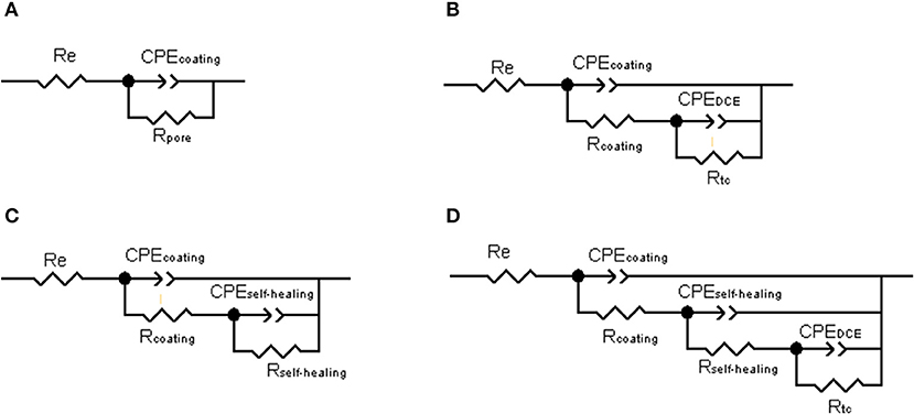
Figure 7. Equivalent circuits for (A) intact coatings; (B) damaged coating without microcapsules; (C) damaged coating with microcapsules; and (D) damaged coating with microcapsules.
Due to the high resistance of the painting systems, especially in the non-defective conditions, the studied frequency range did not allow the extraction of the Rs value directly from the EIS diagrams. For this reason, the value of Rs was kept fixed at 167 Ω·cm2, which is the resistance value of the electrolyte used.
Tables 4, 5 present the values obtained by the circuit model fitting for the EIS experimental data. From the values presented for the samples without damage, it is clear that the presence of microcapsules increased the capacitance of the coating and consequently decreased its resistance by one order of magnitude. Nevertheless, the exponent of the CPEcoating element had no significant variations with microcapsules incorporation, showing that the capacitive behavior of the coating has not been altered in the presence of the additive.
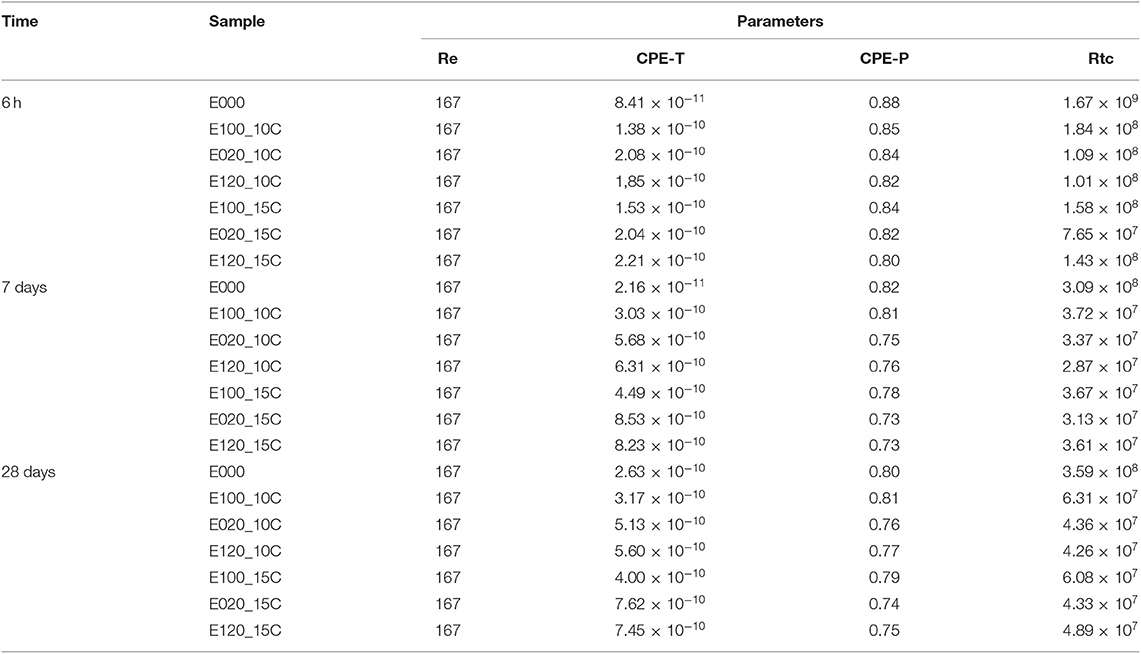
Table 4. Fitting results of EIS data for intact coated samples R (Ω·cm2) and CPE-T (nF·cm2/Sα−1), CPE-P (α).
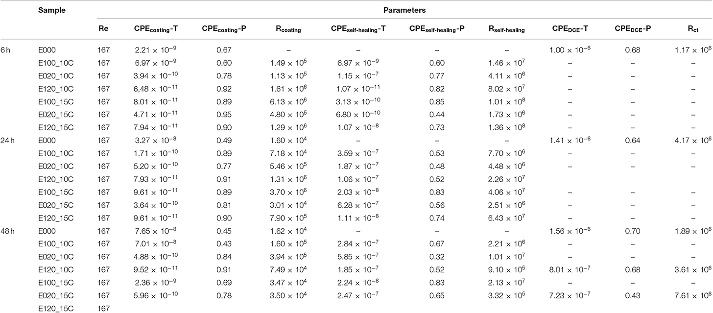
Table 5. Fitting results of EIS data for coated damaged samples R (Ω·cm2) and CPE-T (nF·cm2/Sα−1), CPE-P (α).
From the values presented for the damaged samples, it is observed that the damaged E000 sample showed an increase in the coating capacitance value, resulting in a decrease of the coating resistance value, Rcoating. This behavior results from the defect caused in the coating system, causing its protective properties to decrease, leading to exposure of the carbon steel substrate. Carbon steel exposure may be accompanied by the new circuit element present under damage condition, where the CPEDCE value of 1.0 × 10⁻⁶ F·cm2/Sα−1 is typical of corrosive or charge transfer processes at the metal/electrolyte interface (Szaó et al., 2015).
From the values presented for the damaged samples, it is clear that the self-healing film is present at the damaged region because the Rself-healing values are very close to the values presented for E100_10C sample without damage. The CPEcoating and Rcoating parameters, for the self-repair condition, should be called self-healing CPE and Rself-healing, since the presence of the self-healing film is detected in these circuit elements. Besides, the high Rct value proves that the self-healing effect has been achieved in the microcapsules samples.
SVET Measurements
Figure 8 shows the SVET maps of the ionic currents densities measured above the surface of the carbon steel coated with an epoxy primer containing or not with 10 wt. % and 15% of microcapsules with an encapsulated epoxy ester resin and a provoked defect obtained after different immersion times in 0.01 mol/L NaCl. For the condition without microcapsules, the increasing anodic currents are evident for increasing immersion times, reaching the maximum value after 24 h of immersion. In the presence of microcapsules containing epoxy ester resin, both for 10 and 15 wt. % ratio microcapsules condition, after 6 h of immersion, a significant decrease in ionic currents is evidenced characterizing the self-healing process with active protection in the defect site. Even for 24 h of immersion, no anodic current density appeared in the defect site proving the self-healing properties of the coating system.
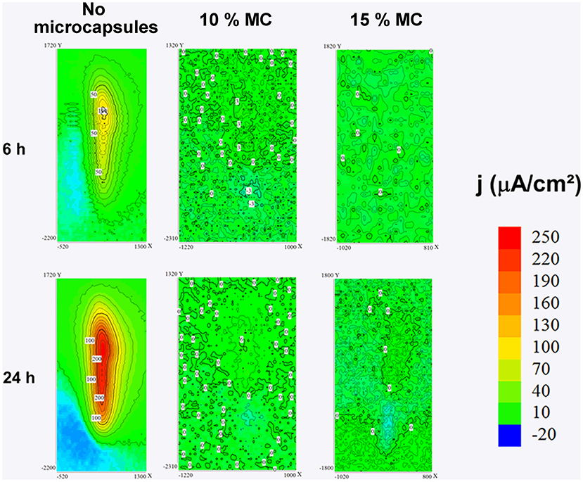
Figure 8. Ionic current densities maps over a provoked defect on coated panels for microcapsules conditions: without microcapsules, with 10 wt. % of microcapsules containing epoxy ester resin, with 15 wt. % of the same microcapsules and the surface aspect after immersion.
Pull-Off Adhesion Test
The results of the pull-off strength of coated samples and the type of failure occurred are presented in Table 6 for different microcapsules conditions. By the average pull-off strength values and the locus of failure presented by the samples, there is no way to affirm that there was a gain or a decrease in the adhesion properties of the coating systems in the presence of the microcapsules. However, what draws attention in this set of results is the low value obtained of pull-off tension for the type of applied coating, since its specification, according to PETROBRAS N-2680 standard, requires a tension of detachment above 12 MPa. Since great care was taken during the preparation of the substrate, which is evidenced by the adhesion of the first layer of the coating system to the substrate, there are indications that the coating used did not meet the expected quality.
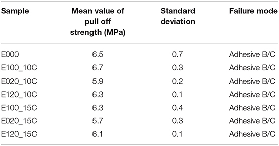
Table 6. Pull off strength of coated samples and observed type of failure.
By visual analysis of the regions where the coating was detached and by the posting dollies, it is noted that there are no differences in the type of failure between the different painting systems studied. The detachment always occurred at the interface of the first and second layers of coating, either in the coated samples containing or not microcapsules. Therefore, we can conclude that poly (urea-formaldehyde-melamine) microcapsules containing the epoxy ester resin did not impair the tack properties of the coating system as a whole. Indeed, against the worst prognostic, this paper shows excellent results proving that the microcapsules do not spoil the adhesion properties of the pigmented coating and they do not show cohesive failure.
Salt Spray Chamber Results
The salt spray results are presented in Figure 9. From the images, it is observed that the pure epoxy coating cannot provide an anticorrosive protection in the scratch zone, due to a large number of observed corrosion products in the damaged region, as a result of iron oxidation. This result shows that the coating system without microcapsules cannot protect the carbon steel against aggressive species and consequently from the corrosion phenomena after damaged. On the other hand, in the self-healing coating, there are no visible corrosion products in the defect region. It suggests that the healing material was released on the damaged zone and a new protective layer was formed in the scratch area. Comparing the two samples it is clear that the microcapsules system increase the coating anticorrosion properties after mechanical damage, due to the self-healing effect. These results are in agreement with the EIS results, where the microcapsules system presented better anti-corrosion properties after damaging.
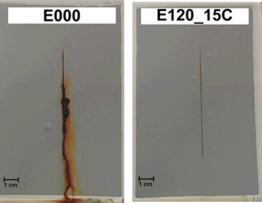
Figure 9. Samples after 720 h in salt spray chamber, without microcapsules E000 and with 15 wt. % microcapsules in the first and second layer E120_15C.
Conclusions
The loading of the coating system with the self-healing microcapsules caused a decrease in the total impedance of each coating system, showing that there was a certain disturbance of the coating system in the presence of the microcapsules. However, the self-healing effect can be verified for all samples containing microcapsules by all electrochemical techniques and corrosion tests employed in this work.
The higher concentration (15 wt. %) of microcapsules in the coating system provided a better self-healing film, with better anticorrosive performance than those with 10 wt. %. Also, the presence of microcapsules only in the second layer of the coating system did not present satisfactory self-healing effects, due to the difficulty of the healing agent reaching the substrate.
The pull-off adhesion tests were significant in proving that the presence of the microcapsules did not in any way damage the adhesion or cohesion properties of the coating system, regardless the layer applied or the number of microcapsules added in the coating.
Data Availability Statement
The datasets generated for this study are available on request to the corresponding author.
Author Contributions
FC performed most of the experimental work because it was part of his Ph.D. thesis. He also gave important contribution to the discussion of data and bibliographic findings. AK acted as a project manager at Petrobras from which the laboratóry received financial support. He advised about the performing long term SSC test and pull off strength adhesion test for practice importance in real life. He has contributed with the final discussion of theses tests results. IA was the head of the Electrochemistry and Corrosion Laboratory at Polytechnic School at USP. She had been the Ph.D. advisor of FC and has acted as the coordinator of the research project. She had planned the work and paper, and had participated in the deep discussion of results.
Funding
The authors declare that this study received funding from PETROBRAS. The funder was not involved in the study design, collection, analysis, interpretation of data, the writing of this article, or the decision to submit it for publication.
Conflict of Interest
AK was employed by the company PETROBRAS.
The remaining authors declare that the research was conducted in the absence of any commercial or financial relationships that could be construed as a potential conflict of interest.
Acknowledgments
The authors were thankful for Petrobras for financial support (Project SAP: 4600508473) and CNPq for doctorate scholarship for FC (Proc 140309/2013-6). The authors were thankful to the Chemical Engineering Department of the FEI University Center, located in the city of São Bernardo do Campo for FTIR-ATR analysis.
References
Adamczak, M., Para, G., Simon, C., and Warszyńki, P. (2013). Natural oil nanoemulsions as cores for layer-by-layer encapsulation. J. Microencapsul. 30, 479–489. doi: 10.3109/02652048.2012.752536
Behzadnasab, M., Mirabedinia, S. M., Esfandeha, M., and Farnoodb, R. R. (2017). Evaluation of corrosion performance of a self-healing epoxy-based coating containing linseed oil-filled microcapsules via electrochemical impedance spectroscopy. Prog. Org. Coatings 105, 212–224. doi: 10.1016/j.porgcoat.2017.01.006
Bekas, D. G., Tsirka, K., Baltzis, D., and Paipetis, A. S. (2016). Self-healing materials: a review of advances in materials, evaluation, characterization and monitoring techniques. Compos. B Eng. 87, 92–119. doi: 10.1016/j.compositesb.2015.09.057
Cailleux, E., and Pollet, V. (2009). “Investigations on the development of self-healing properties in protective coatings for concrete and repair mortars,” in 2nd International Conference on Self Healing Materials (Brussels), 120.
Chike, K. E., Myrick, M. L., Lyon, R. E., and Angel, S. M. (1993). Raman and near-infrared studies of an epoxy resin. Appl. Spectrosc. 47, 1631–1635. doi: 10.1366/0003702934334714
Cotting, F., and Aoki, I. V. (2016). Smart protection provided by epoxy clear coating doped with polystyrene microcapsules containing silanol and Ce (III) ions as corrosion inhibitors. Surf. Coatings Technol. 303, 310–318. doi: 10.1016/j.surfcoat.2015.11.035
Ebrahiminiya, A., Khorram, M., Hassanajili, S., and Javidi, M. (2018). Modeling and optimization of the parameters affecting the in-situ microencapsulation process for producing epoxy-based self-healing anti-corrosion coatings. Particuology 36, 59–69. doi: 10.1016/j.partic.2017.01.010
Fayyad, E. M., Almaadeed, M. A., and Jones, A. (2015). Encapsulation of tung oil for self-healing coatings in corrosion applications. Sci. Adv. Mater. 7, 2628–2638. doi: 10.1166/sam.2015.2583
Huang, M., and Yang, J. (2011). Facile microencapsulation of HDI for self-healing anticorrosion coatings. J. Mater. Chem. 21, 11123–11130. doi: 10.1039/c1jm10794a
Khorasani, S. N., Ataei, S., and Neisiany, R. E. (2017). Microencapsulation of a coconut oil-based alkyd resin into poly(melamine-urea-formaldehyde) as shell for self-healing purposes. Prog. Org. Coatings 111, 99–106. doi: 10.1016/j.porgcoat.2017.05.014
Knop, W. R., Meier, M. M., and Pezzin, S. H. (2014). Preparação e caracterização de microcápsulas de poli (ureia-formaldeído) preenchidas com diciclopentadieno. Rev. Mater. 19, 266–273. doi: 10.1590/S1517-70762014000300010
Liu, J., Gong, G., Zhong, Y., Gu, Y., and Zhang, F. (2015). Preparation of poly(urea-formaldehyde) microcapsules filled with epoxy resins via in-situ polymerization method. Hecheng Shuzhi Ji Suliao/China Synth. Resin Plast. 32, 1–9.
Montemor, M. F. (2014). Functional and smart coatings for corrosion protection: a review of recent advances. Surf. Coatings Technol. 258, 17–37. doi: 10.1016/j.surfcoat.2014.06.031
Montemor, M. F., Pinto, R., and Ferreira, M. G. S. (2009). Chemical composition and corrosion protection of silane films modified with CeO2 nanoparticles. Electrochim. Acta 54, 5179–5189. doi: 10.1016/j.electacta.2009.01.053
NACE International (2016). IMPACT–International Measures of Prevention, Application and Economics of Corrosion Technologies Study (Houston, TX).
Petrobras, Paulo, U. D. S., Aoki, I. V., Lachtermacher, M. G., Coelho, J. F. C., A, K., et al. (2012). Revestimento Autorregenerante Contendo Agentes de Autorreparação. Rio de Janeiro.
Samadzadeh, M., Boura, S. H., Peikari, M., Ashrafi, A., and Kasiriha, M. (2011). Tung oil: an autonomous repairing agent for self-healing epoxy coatings. Prog. Org. Coatings 70, 383–387. doi: 10.1016/j.porgcoat.2010.08.017
Sánchez-Silva, L., Rodríguez, J. F., and Sánchez, P. (2011). Influence of different suspension stabilizers on the preparation of Rubitherm RT31 microcapsules. Colloids Surf. A Physicochem. Eng. Asp. 390, 62–66. doi: 10.1016/j.colsurfa.2011.09.004
Singh, A. P., Gunasekaran, G., Suryanarayana, C., and Baloji Naik, R. (2015). Fatty acid based waterborne air drying epoxy ester resin for coating applications. Prog. Org. Coatings 87, 95–105. doi: 10.1016/j.porgcoat.2015.05.012
Siva, T., and Sathiyanarayanan, S. (2015). Self healing coatings containing dual active agent loaded urea formaldehyde (UF) microcapsules. Prog. Org. Coatings 82, 57–67. doi: 10.1016/j.porgcoat.2015.01.010
Szaó, T., Telegdia, J., and Nyikos, L. (2015). Linseed oil-filled microcapsules containing drier and corrosion inhibitor–their effects on self-healing capability of paints. Prog. Org. Coatings 84, 136–142. doi: 10.1016/j.porgcoat.2015.02.020
Vakhitov, T. R., Katnov, V. E., Grishin, P. V., Stepin, S. N., and Grigoriev, D. O. (2017). Biofriendly nanocomposite containers with inhibition properties for the protection of metallic surfaces. Proc. R. Soc. A Math. Phys. Eng. Sci. 473:20160827. doi: 10.1098/rspa.2016.0827
Vašková, H., and Křesálek, V. (2011). “Raman spectroscopy of epoxy resin crosslinking,” in Proceedings of the 13th WSEAS International Conference on Automatic Control, Modelling & Simulation, 357–361.
White, S. R., Sottos, N. R., Geubelle, P. H., Moore, J. S., Kessler, M. R., Sriram, S. R., et al. (2001). Autonomic healing of polymer composites. Nature 409, 794–797. doi: 10.1038/35057232
Keywords: self-healing, epoxy ester resin, polymeric microcapsules, pull-off adhesion, SVET, EIS
Citation: Cotting F, Koebsch A and Aoki IV (2019) Epoxy Self-Healing Coating by Encapsulated Epoxy Ester Resin in Poly (Urea-Formaldehyde-Melamine) Microcapsules. Front. Mater. 6:314. doi: 10.3389/fmats.2019.00314
Received: 17 March 2019; Accepted: 20 November 2019;
Published: 05 December 2019.
Edited by:
Flavio Deflorian, University of Trento, ItalyReviewed by:
Ioannis A. Kartsonakis, National Technical University of Athens, GreeceMario G. S. Ferreira, University of Aveiro, Portugal
Copyright © 2019 Cotting, Koebsch and Aoki. This is an open-access article distributed under the terms of the Creative Commons Attribution License (CC BY). The use, distribution or reproduction in other forums is permitted, provided the original author(s) and the copyright owner(s) are credited and that the original publication in this journal is cited, in accordance with accepted academic practice. No use, distribution or reproduction is permitted which does not comply with these terms.
*Correspondence: Fernando Cotting, ZmVybmFuZG9AZGVxLnVmbWcuYnI=