- 1Evolutionary Biology of Invertebrates, Institute of Evolution and Ecology, University of Tübingen, Tübingen, Germany
- 2Institute of Applied Physics, Vienna University of Technology, Vienna, Austria
Bio-inspired by compound eyes in insects, the authors identify advantages of such an optical system and propose a novel optics that combines basic principles from compound eyes with an additional technical zooming feature. The 3D-printed, bio-inspired fiber optic set-up is based on ommatidia, the small single components of compound eyes. The advantageous aspects that are transferred from the inspiring organisms are that no focusing on objects is needed and a maximum depth of focus is always achieved. Two adjustable technical features are an adjustable field of view per pixel and a zooming possibility, not found in animals. Prototypes were produced as a proof of concept. One of them was manufactured using a stereolithography 3D printer. They were positively tested with regard to the implemented features. Optional further functionalities and developments are discussed. Possible applications of the 3D-printed, bio-inspired designs are optical devices that benefit from adjusting the field of view per pixel to zooming. Suggested are novel microscopes and screens with built-in cameras enabling online eye-to-eye communication without having to concentrate on the location of a camera.
Introduction
Insects and crustaceans have compound eyes composed of tiny units known as ommatidia (Warrant and McIntyre, 1993; Kirschfeld, 2001; Land and Nilsson, 2012). Given the huge group of insects within the Animalia, most species with eyes have compound eyes. This is also valid in terms of the number of individuals on our planet (Land and Nilsson, 2012, p. 157). The classical physiological work by Exner (1891) is a morphological milestone in dealing with compound eyes from a functional point of view. That work inspired this paper. Apposition eyes (Figure 1) are characterized by the fact that rhabdoms—the light guides and receptors in the ommatidia—receive light only from their “own” facet (Nilsson, 1989, p. 38).
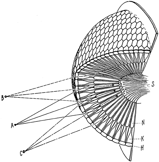
Figure 1. Scheme of an apposition compound eye. The object points A, B, C in the environment correspond to the points a, b, c in the ommatidia. H, cornea; K, crystalline cone; N, receptor cell; S, optic nerve. Cf. Figure 3 left. Reprinted by permission from Springer Nature (Karl von Frisch, Aus dem Leben der Bienen) © Frisch (1977).
The optical systems have evolved a structure-function-relationship that is tangible not only for biologists but also for engineers working on novel approaches in technical optics. A relatively straightforward relationship between structure and function in such eyes enables biomimetic transfer (Drack et al., 2018): identified basic functions and working principles of the biological system are used to conceptualize a technical device. The main reason why engineers mimic whole compound eyes is that these structures have a wide field-of-view. Attempts have been made to implement such a feature in artificial imaging systems on the same length scale as in insect eyes (Jeong et al., 2006). Another reason is the small size of compound eyes, which is interesting for tiny engineered devices (Duparré and Wippermann, 2006). Due to their smallness, compound eyes have low, but sufficient, visual resolution (Kirschfeld, 1976). Several research groups have developed artificial compound eye optics. For reviews see Lee and Szema (2005), Duparré and Wippermann (2006), Lakshminarayanan and Parthasarathy (2016), Song et al. (2017) Wu et al. (2017), Lee et al. (2018), and Cheng et al. (2019).
Conventional technical optic devices are constructed with lenses that require image focusing in order to adapt the lens system to the distance from the observed object. In contrast, in a biological optical system based on one lens—as in animals with lens eyes—focusing can be achieved by either changing the focal depth of the lens or by moving the lens along the optical axis. Neither of these options is necessary in the insect eye: One extraordinary feature in optics based on facets is that no focusing on objects in different distances is needed. No optical lenses have to be moved to obtain the image. As the optics are not focused on a specific distance, this also means that the depth of field is very large, ranging from very close to the eye to infinity (Land and Nilsson, 2012, p. 168).
In this paper a construction is proposed that mimics certain features of apposition compound eyes—such as found in various insect eyes. Two technical features are introduced: an adjustable field of view per pixel and a zooming possibility. The zooming functionality is not known from compound eyes.
For proof of concept, 3D printing was applied. One major advantage of this rapid prototyping technology is the simple and fast way to test whether one has fully understood the working principles of multi-functional biostructures. The multi-functionality of structures in living beings—the eyes are not only optical devices, but also consist of living cells with metabolism etc.—is the basis for their over-all expediency (and perhaps also beauty), but also makes it difficult to identify, select, and transfer the requisite basic principles to a biomimetic device. This multi-step process can be sped up by 3D printing.
Materials and Methods
Compound Eyes: The Biological Concept Generator
Due to their morphological features, each ommatidium (Figures 1, 2) in a typical apposition eye receives light from only a small cone (Figure 3 left). The angle of this light cone—the so-called acceptance angle of a single ommatidium (Land and Nilsson, 2012, p. 168), which here is referred to by α—limits the resolution of the whole optical system; the smaller the angle, the higher the possible resolution. This angle corresponds to the circle diameters in Figure 3 right. Light passes through the cornea (with corneal facet lenses) and the crystalline cones to the receptor cells that form the rhabdoms.

Figure 2. Ommatidia of the honey bee Apis mellifera Linnaeus, 1758 (Apidae), stained. Light passes through the cornea (with corneal facet lenses) and the crystalline cones to the receptor cells that form the rhabdoms. At the basement membrane the optical part of the eye ends. © Stephan Handschuh (2014). Image reproduced with permission.
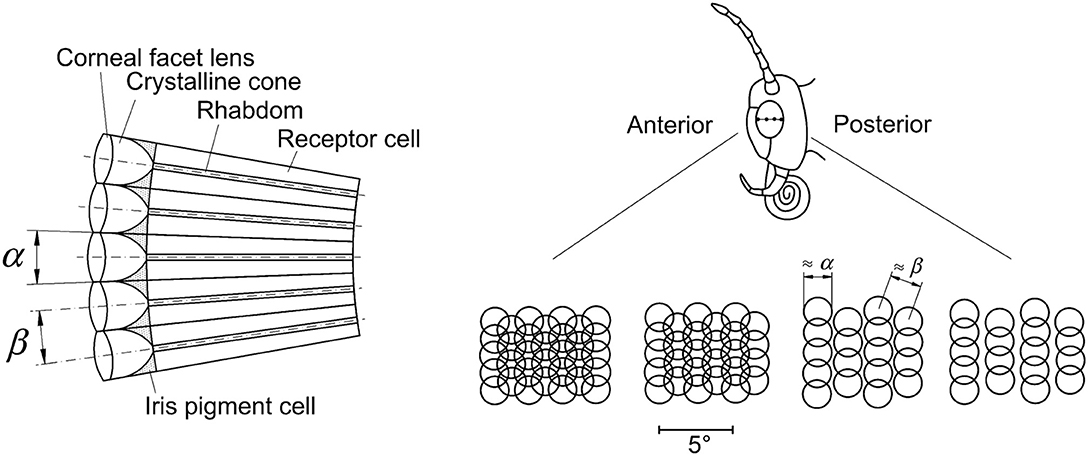
Figure 3. Left: Five ommatidia are shown schematically, each with a lens, a crystalline cone, a rhabdom and receptor cells. The receptor cells are synaptically connected to neurons (not shown). The angle α is the acceptance angle of a single ommatidium, and the angle β is the angle between the axes of two neighboring ommatidia, referred to as the inter-ommatidial, or inter-receptor angle. Right: The top picture shows a butterfly head from the left side with the eye in the middle. Indicated are the positions from where the receptive fields are shown in the bottom row. In most flying insects, the ommatidial receptive fields are not always separated, but may overlap (Land and Nilsson, 2012). Going from anterior to posterior they change in the depicted case from overlapping “horizontally” and “vertically” to overlapping only “vertically.” The angle α from left corresponds to the diameters of the circles representing the ommatidial receptive fields, and the angle β corresponds to the distance between the centers of neighboring circles. Smaller angles β in the front of the head (anterior), i.e., overlapping circles, and larger ones laterally (more posterior) are apparently advantageous in fast forward flight.
In species with apposition eyes only the combined intensity of all light rays across the field of view of one ommatidium is sensed (Land and Nilsson, 2012, p. 161–164). Accordingly, the small lenses in the cornea and the crystalline cones (Figure 1) focus the incoming light toward the tip of the rhabdom, which serves simultaneously as light guide and receptor.
The so-called inter-ommatidial or inter-receptor angle (Land and Nilsson, 2012, p. 158), here termed β, is the angle between the optical axes of two neighboring ommatidia (Figure 3 left). It relates to the distance between the centers of neighboring projected circles, representing the fields of view of individual ommatidia (or ommatidial receptive fields) in Figure 3 right. This angle is not constant across one whole eye, but can vary according to the position of the eye, (e.g., in anterior-posterior direction).
In the compound eyes of animals, both the angles α and β can have different values throughout an eye: depending on the position, they can differ in one animal. Even though Figures 2, 3 left might suggest otherwise, some parts of compound eyes are flexible. Pigments can move, the shapes of the crystalline cones and the rhabdoms can change, for example depending on day or night light conditions (Meyer-Rochow, 1999). Narendra et al. (2013) have shown that the acceptance angle α can be changed as a (side) effect in protecting the photoreceptors from bright light. Adjusting the parameter β might occur, but evidence is lacking (Meyer-Rochow, 1999).
3D Printing and Fibers
Additive manufacturing, rapid prototyping and 3D printing (Gibson et al., 2015) are fast-growing fields. Various printing methods and materials are available, even for private purposes. Each method has its respective advantages and shortcomings.
As smooth surfaces are required in the here proposed facet optics, fused filament fabrication is not an option. The stereolithography (SLA) printer Form 2 from Formlabs (Somerville, MA, USA) was used. The CAD models were drawn with Autodesk Inventor® (version 2018). Formlabs internal software PreForm (version 1.15.3) was used to process the CAD models. Formlabs standard gray resin FLGPGR02 and black resin FLGPBK02 were used (Formlabs, 2017).
The PMMA fibers used in prototype 2 stemmed from the POF cable I-V2Y(ZN)Y 2P980/1000, available at: http://media.klinkmann.fi/catalogue/content/data_fe/Leoni/LEONI_Fiber_optic_cables_assemblies_connectors_and_accessories.pdf (accessed June 27, 2020).
Transferable and Additional Features
Identification of Physical Principles and Their Transfer to Engineering
The basic arrangement of apposition eyes with their separated ommatidia is applicable in engineering applications. In the technical realization, an optical fiber mimics the light guide in the ommatidium (Figure 4). Similar to the multitude of ommatidia in the living concept generator, a large number of fibers can be used. The technical analog to the receptor cells can be an image sensor (e.g., CMOS, CCD) directly attached to the ends of the fibers. This works differently than in the eye, where the light guide and the receptor are one elongated structure.

Figure 4. An optical fiber consisting of two materials with different refractive indexes (n1 > n2). Light with an angle of incidence that is smaller than the acceptance angle Θmax can enter and is transmitted.
The characteristics of the optical fibers are decisive for a technical device. An important parameter in optical fibers is the numerical aperture (NA). The larger the NA, the larger the range of angles from which light can enter the fiber. In the ideal case for our purposes—and if many fibers are present—the NA for light entering the fiber should be close to zero, i.e., capturing only close to parallel light.
The numerical aperture of optical fibers is related to the angle of the cone from which light is received and directed through the fiber (Figure 4). This acceptance angle of an optical fiber Θmax depends on the refractive indices of the fiber's core and the cladding, n1 and n2 respectively. The acceptance angle denotes the maximum angle at which incident light can enter the fiber. The values for n1 and n2 are chosen to achieve total reflectance in a cylindrical straight fiber. In air, with n0 = 1, the NA is the sinus of the acceptance angle Θmax (Equation 1).
For a typical fiber, the core has a higher refractive index than the cladding, e.g., for glass fibers a combination could be n1 = 1.62 and n2 = 1.52 (Schott, 2020). For low numerical aperture fibers with silica core and cladding, the values can be n1 = 1.449 and n2 = 1.444 (Fiberguide Industries, 2017). Following equation 2, this results in 2Θmax = 68.2° for the glass fibers and 2Θmax = 13.8° for the low numerical aperture fibers.
In the case where the optical system consists solely of fibers, the angle α that determines the field of view is equivalent to 2Θmax. In cases where additional components, such as tubes, are used to reduce the field of view per “facet unit” (see below), α is smaller than 2Θmax. The angle α denotes the maximum angle at which incident light can enter the “facet unit” (see Figure 5).
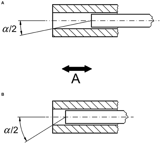
Figure 5. Technically adjustable feature A: Adjustable field of view per pixel. Moving the fiber back and forth along its axis in the tube changes the angle α at which light can enter the fiber. With larger distance between tube end and fiber end shown in (A), the angle α is smaller than in (B). For ease of representation, the core diameter of the fiber is assumed to be small.
Adjustable Technical Features
Two new features are introduced: an adjustable field of view per pixel by changing the parameter α and a new zooming feature by changing the parameter β (cf. Figure 3 left).
Firstly, the field of view per pixel is adjustable. One possible option as realized in the prototypes (see below) is by changing the position of the end of the fiber relative to the end of a tube (Figure 5). As α decreases, the light intensity detectable at the image side of the fiber decreases accordingly. At the same time the overlap with the field of view with neighboring technical “ommatidia” is reduced. This can be advantageous for processing the information content in the image sensor and subsequent processing steps.
Secondly, a zooming feature can be achieved by altering the angle β between the fibers and respective tubes (Figure 6). When β is large, a zoom state comparable to a wide-angle lens is acquired. When β is reduced, a smaller area of an object with more details can be imaged, analogous to a telephoto lens. This is a unique technical feature as opposed to compound eyes, where no zooming feature has been described.

Figure 6. Technically adjustable feature B: Zooming feature. The angle β between the axes of the single tubes can be varied. In (A) the angle β is small, comparable to a telephoto lens used in conventional photography. In (B) the angle β is larger, comparable to a wide-angle lens.
Results
Bio-Inspired Facet Optics—the Prototypes
Two prototypes have been constructed, produced and tested. Prototype 1 (Figure 7) basically consists of two wooden frames holding metal grids and brass tubes with polymer fibers. Frame 1 is fixed to four rods. The rods are also used as mechanical guidance for moving frame 2, enabling changing the distance between the frames and attached metal grids. Grid 1 has a mesh width of 1 mm, grid 2 has a slightly larger mesh width of 1.2 mm. Brass tubes with 50 mm length and an outside diameter of 1.0 mm and inside diameter of 0.5 mm were used. Each of the 900 tubes (in a 30 × 30 rectangular arrangement) is attached with glue and friction to the small-meshed grid 1 such that they cannot move in axial direction, but the angles between the tubes can be altered. The other ends of the tubes are loosely placed in the holes of grid 2 with the larger mesh width. To ensure that the angles β between the tubes are equally distributed, rubber bands push apart the single tubes. The polymer fibers (diameter 0.4 mm) are inserted into the tubes from the image side, all at equal length at the object side and bundled together at the image side. An image sensor can be mounted at the parallel end of the fiber bundle.
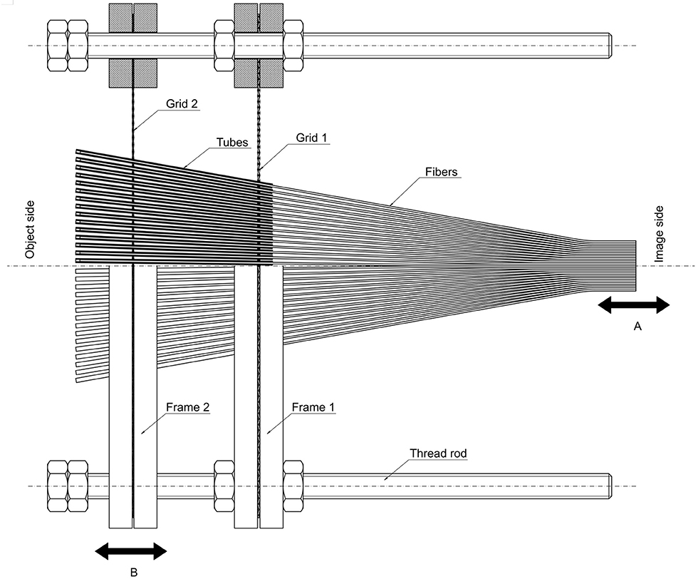
Figure 7. Prototype 1 consists of two grids with different mesh widths. The 30 × 30 tubes, in which the fibers are located, are axially fixed to grid 1. Angle α can be changed by moving the bundle of fibers relative to the tubes (distance A). Grid 2, which has a slightly larger mesh width, can be moved (distance B) so that the angles β between the single tubes are changed. The object is located on the left side of the figure (object side), and its image is detected on the right side of the figure (image side), at the back ends of the fiber bundle.
In the experimental proof of concept, the fibers are moved (distance A in Figure 7) in axial direction in the tubes, thereby changing the distance between fibers' left front ends and tubes' left ends, according to Figure 5. This changes the angle α, narrowing the angle of the cone of light that can enter and therefore also the field of view per pixel. α is maximally 2 Θmax.
Measurements on the prototype's brass tubes and fibers were made to determine the angle α—as a function of the distance between tube end and fiber end—by sending light from the image side through a fiber. This method can be applied because, geometrically, the optical paths are similar when reversing them, and it is easier to measure a light spot diameter rather than putting a point light source at different angles on the object side and determining what goes through the fiber. When the fiber end was retracted 15 mm from the front end of the tube (on the object side), α was roughly 3°.
For the zooming feature, the front frame 2 with grid 2 is moved relative to the back frame 1 with grid 1 (distance B in Figure 7). Altering this distance between the frames changes the angles β between the tube axes geometrically with respect to mesh width and distance between the grids, according to Figure 6. When the frames are close to each other, the angles β are larger (comparable to a wide-angle lens); when the frames are far from each other, the angles β are small and the area depicted from the object side is smaller (comparable to a telephoto lens).
Both adjustable features were demonstrated to work, but the image quality was low. The rather unsophisticated fibers used captured only little light when far inside the tubes. This called for strong illumination of the objects. The reflecting inner sides of the brass tubes lead to blurring at the image side. Furthermore, the friction between the tubes and grid 2 is high.
In prototype 1 the most difficult task was producing the components and assembling them piece by piece. With 3D printing—as in a test print and prototype 2—however, precise manufacturing was much easier and the tubes can be printed directly in the correct arrangement without any further manipulation. This helps ensure that all the tubes meet specification lengths. This also circumvents the problem of mounting the tubes to grid 1. The test print was produced as an intermediate step to determine optimal print settings and dimensions (e.g., of tube inner diameters), whereas prototype 2 tested both the print settings and optical properties.
The test print and prototype 2 were made using stereolithography 3D printing. Initial attempts were made with 19 tubes (Figure 8), then with 91 tubes (Figure 9). Grid 1 and the tubes from prototype 1 were, in the successive constructions, combined in one 3D-printed part—further referred to as base plate plus tubes (cf. Figures 8, 9). The equivalent to grid 2 was printed separately. CAD files of prototype 2 can be found in the supplementary material (available at https://doi.org/10.5281/zenodo.3820635).
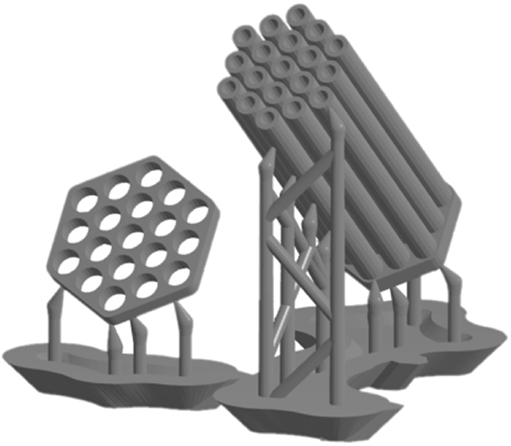
Figure 8. Test print with 19 tubes and the support structures for printing. Left: movable grid. Right: Tubes and base plate combined. The automatically generated support structures were designed with minimum density and minimum recommended point size.
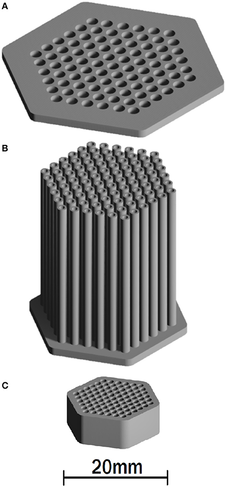
Figure 9. CAD-models of the 3D-printed parts of prototype 2 with 91 tubes. (A) The movable grid. (B) Tubes and base plate in one part. (C) Scaffold for the fibers at the image side. The tubes have slightly different lengths, i.e., longer in the center, so that the angles α in each facet are the same, considering the equal lengths of the fibers.
The fibers (0.96 mm outside diameter) consist of PMMA with n1 = 1.49 and n2 = 1.40 (I-V2Y(ZN)Y 2P980/1000, outer jacket removed, fibers separated). Plugged into equation 1, this yields a numerical aperture NA = 0.51. With n0 = 1.00 for air, the angle 2Θmax = 61.3°. As noted above, even lower angles would be possible by using other fibers. In comparison, prototype 1 used fibers without cladding, so the reflection occurred on the border between the fiber and the surrounding air. The quality of prototype 1 was also limited by the brass tubes, which reflect light, leading to a blurring of the image. This can no doubt be mitigated by using other materials. In the test print, the 3D-printed parts are made of Formlabs standard gray resin FLGPGR02, whereas prototype 2 used black resin FLGPBK02. The black resin results in rather matte surfaces of printed parts and hence lower reflection, which reduces noise due to scattered light. Both resins have the same tensile modulus of 2.8 GPa, which would even drop to 1.6 GPa without post-curing under ultraviolet light (Formlabs, 2017). This is low enough to enable bending of the tubes relative to the directly connected base plate. In prototype 1 this bending of the tubes did not occur due to the different connecting mechanism.
A tighter hexagonal packing was chosen because the packing was not bound to metal grids. Many compound eyes are also arranged in this manner. After test printing, an inner tube diameter of 1.3 mm was found to be optimal to minimize both friction and clearance between the acrylic fibers and the tubes. The trade-off between robustness on the one hand and compactness and flexibility on the other hand was decisive for tube wall thickness, which in prototype 2 was set to 0.45 mm. A 0.8 mm distance between the outsides of neighboring tubes at the base plate yielded a compact yet flexible arrangement. The middle tube is 30 mm long. Toward the outside, the tubes gradually become shorter until the outermost tubes are 29.4 mm long. This ensures that the angle α is the same for each equally long 100 mm fiber. The fibers for the prototypes were cut exactly perpendicular to the axis with a sharp knife. To even out the cut surfaces at the end faces, they were gently pressed against a heated flat iron covered with pan liner. The longer middle tubes also help in mounting the movable grid (equivalent to grid 2 in prototype 1), the most tedious assembling step. The movable grid has the same number of holes in the same pattern as the base plate. The distance between the axes of two holes, however, is 3.7 mm. Thus, the tubes spread out at angles β depending on the distance between the base plate and the movable grid. The hole diameters in the movable grid are 2.6 mm so that the tubes can still fit in the grid when they are slightly tilted. The ideal proportions for the 3D-printed structures in prototype 2 were determined in an iterative process involving test printing. This required considering the resolution of the printer, printing material properties and shrinking of the cured resin.
The internal software PreForm for the Form 2 printer, Formlabs (Somerville, MA, USA), was set to minimum density and minimum recommended point size to automatically generate support structures for the 3D object. Thereafter, the support structures could be manually edited. Special care was taken to avoid putting support structures inside or in between the tubes. The removal of such support structures would bear the risk of destroying the tubes. Furthermore, residuals of the support structures could increase the friction of the fibers inside the tubes or, outside, of the movable grid, even leading to blockage. A crucial aspect for the tubes was that they are oriented such that the base plate was printed first (Figure 8) at a tilt angle of 45°. These settings ensured that support structures were correctly placed automatically, that all newly printed material had sufficient support structures to carry it, and that deformation was reduced to a minimum. The chosen tilt angle also prevented tube clogging because the excess resin could drain.
A separate part—referred to as the scaffold—was printed for prototype 2 to hold the fibers at a constant and fixed distance at the image-side. To keep those fibers at the image-side as close to each other as possible, a small wall thickness had to be chosen for the scaffold, into which the fibers were glued with a modeling adhesive (UHU Allplast Spezialkleber). Thereby, all the fibers are arranged in parallel at the image side. Due to the cladding of the fiber, the glue does not affect the optical properties. The length of the scaffold in prototype 2 is 8.0 mm in order to enable a stable grip when adjusting the acceptance angle by pulling or pushing the fiber bundle.
Several problems were encountered while determining good print settings. The tubes can deform during curing, the resin can become stuck and harden in the thin tubes, thereby clogging them, and the support structures must be removed very carefully to avoid damaging the relevant parts. The tubes can also crack if wall thickness is too small. While printing and curing, the thin tubes stayed intact but were prone to breaking due to mechanical force or bending.
To assemble the prototype, in a first step the acrylic fibers were glued into the scaffold. Special care had to be taken to ensure that all fibers ended in one plane. In the next step, all tubes were threaded into the corresponding holes of the movable grid. This was done with each tube individually row by row. Finally, the acrylic fibers were inserted into the ends of the corresponding tubes at the base plate. Again, all fibers had to be threaded one after the other.
The completely assembled prototype 2 is depicted in Figure 10. As additional features, limit stops were introduced. These prevented the movable grid from slipping out of the tubes. In a separate approach, strings were used to prevent the fiber bundle from slipping out of the tube.
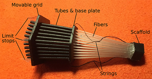
Figure 10. Completely assembled prototype 2 with 3D-printed parts and 91 fibers. The object side is left and the image side at the scaffold is right. The whole device is ~120 mm long.
Testing Prototype 2
Prototype 2 is fully functional with respect to both adjustable features. For measuring the angle α, the tip of one single tube was kept at a constant distance from a millimeter-scaled paper. Then the fiber was put into the tube at different distances l between tube end and fiber end. Light was coupled in on the other end of the fiber, i.e., measurements were taken with light going in the opposite direction compared to taking pictures with the device. The diameters d of the resulting light spots on the paper were measured in five repeated measurements for different positions. Therefrom α was calculated as shown in Table 1.

Table 1. Relationship between fiber-tube-distance and angle α for fibers and tubes as used in prototype 2.
The angle α can be adjusted between 48.8 and 4.5° depending on the position of the scaffold. The angle β can be varied between 4 and 12° geometrically, depending on the position of the movable grid.
To test the newly introduced features in imaging, two different pictures were used as objects (Figures 11A,D) and viewed through prototype 2 with different settings of the angles α and β. The first picture was a black cross with sharp edges on white background. The second consisted of concentric circles with changing colors. They were placed at about 10 and 30 cm, respectively, in front of the tubes.
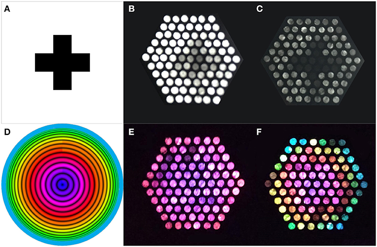
Figure 11. Testing prototype 2 with two different pictures to illustrate changes in α and β separately. In the top row, (A) Shows the picture used at the object side, a black cross on white background placed about 10 cm in front of the tubes. In this experiment α was changed while keeping β constant. Images (B,C) are photographs taken on the image side of prototype 2, with (B) large and (C) small α. The difference in light intensity and blurring is clearly visible. Image (B) has abundant light, but the cross can hardly be distinguished. In image (C) the cross can clearly be seen. In the bottom row, (D) Shows the picture of concentrically colored circles at the object side, placed about 30 cm in front of the tubes. Now β was altered while keeping α constant. Images (E,F) are again photographs taken on the image side of the device. β is small in (E), corresponding to only the inner circles of the provided picture, and large in (F), where the outer bluish part of the picture can also be seen on the image side. This clearly illustrates the zooming feature.
Figure 11 shows the result of changing the two angles at the image side. In the top row, the acceptance angle α is changed, showing the connection between brightness and sharpness. The acceptance angle of the mere fiber is too large to yield a clear picture (Figure 11B). A reduced angle α of 3 to 4° results in a relatively good resolution and sharper edges, but a dimmer image (Figure 11C). The bottom row shows results for changing angle β between the tubes. Here, the zooming feature is clearly recognizable with small and large β (Figures 11E,F).
Discussion and Outlook
The development, construction, and testing phases all showed that the optical features work using the newly introduced mechanical devices. Prototype 1, as a basic proof of concept, worked well with respect to the adjustable features. Here, individual components and settings were changed and improved, revealing the important issues for higher-quality optics and improving on mechanical issues such as friction. Based on these insights on issues that could be improved with higher-quality materials and easier construction and manufacturing via 3D printing, the test print and prototype 2 were produced. The 3D-printed prototype is a major improvement over prototype 1 with regard to optical quality as well as ease of (digital) manufacturing and assembling. Prototype 1 required more time to manufacture. The 3D-printed prototype, however, had fewer fibers and hence “pixels.”
Prototype 2 has the advantage of being easy to reproduce with a constant quality. Modifications are relatively simple to realize because the construction is available in digital form. The image plane is stable and flat through the scaffold, without the risk of slipping fibers. Prototype 2 is less prone to errors during construction because it has fewer parts and many of those are already printed in the correct size and position, with no need for cutting. Difficulties with 3D printing arise when using more fibers and tubes. Threading the movable grid becomes more difficult. Moreover, frictional resistance increases. When used under changing mechanical stress, individual acrylic fibers can break.
Further developments toward real world applications will involve thinner fibers and higher resolution. In the following, we discuss potential improvements of the proposed facet optics in the sequence optical improvements, mechanical improvements, additional ideas, and 3D-printing challenges.
Optical Improvements
A simple calculation yields the approximate size of the facet optics: For a 10 megapixel facet optics device with 4:3 aspect ratio (3,648 × 2,736 pixels) and a fiber diameter of 10 μm (which is typical for fibers in flexible endoscopes), the size of the bundle of fibers excluding the tubes would amount to ~36 × 27 mm. To date, the resolution that can be achieved with lens optics is better, also in animals. For instance, Kirschfeld (1976, p. 365; 1984) calculated that a compound eye with the same spatial resolution as a human eye would require a 1-m-diameter surface area. Such high resolutions, however, are not needed in all technical applications or, alternatively, there might be no spatial restrictions.
In the here proposed facet optics, the spatial resolution of the visual field imaged on a given area is limited by the diameters of the fibers and the tubes as well as the pixel size of the image sensor. The low spatial resolution in the biological concept generator, where heads are small, is not an issue for the technical implementation.
An important issue is the rather large acceptance angle in the prototypes so far. Various potential solutions are available to reduce this angle—and thereby the field of view per pixel—in a next generation, but at the same time capture more light. Accordingly, minimizing the gap between the tube and the fiber in radial direction enhances the accuracy, but raises a friction problem. Mimicking the microlenses in the ommatidia (Figure 3 left) by locating a lens at the entrance of each tube (Figure 12 left), with a focal point at the front end of the fiber, would be closer to the biological concept generator (Figures 1–3 left). Another option would be to use a radially layered lens cylinder (Figure 12 right). Exner already noted that the principle of the layered cylinder might be applied in compound eyes, with a gradient in refractive index in radial direction leading to light rays becoming bent (Exner, 1891: Figure 5). In insects, this principle is found in the proximal end of the crystalline cones of butterflies (Land and Nilsson, 2012, p. 165). Using a multimode graded refractive index fiber which is cut in the proper distance helps focus parallel light rays (Schröder and Treiber, 2014, p. 167) and could be attached as a lens cylinder to the tubes. A radially layered lens cylinder can furthermore be combined with a diaphragm (Figure 12 right), comparable to the pigments in an insect eye (Figure 3 left).

Figure 12. Left: A possible improvement to narrow the angle α involves using a lens before light enters the fiber, similar to the situation in compound eyes (cf. Figure 3 left). Right: Another possible strategy to narrow angle α is using a lens cylinder (Exner, 1891) [also termed: gradient index rod lens; Hecht (2017, p. 284); Edmund Optics, Available at: https://www.edmundoptics.com/optics/optical-lenses/aspheric-lenses/Gradient-Index-GRIN-Rod-Lenses/ (accessed February 16, 2018)] before light enters the fibers (on the right side behind the diaphragm; not shown). The refractive index n in such a cylinder gradually decreases with distance from the axis. This lets the light beams in the cylinder converge. With proper cylinder length, this can be advantageous. In a longer lens cylinder, light periodically converges, and diverges. A diaphragm before the fiber can help to additionally narrow angle α.
Even though the ommatidia in Figure 2 appear to be curved, almost resembling waves, this is a preparation artifact. Nevertheless, technical fibers can be bent, with the effect of decreasing angle α (Schröder and Treiber, 2014, p. 165f). No biological equivalent of this approach has yet been reported in the literature. Bending a technical fiber with a core diameter D along a bending radius r reduces the angle Θmax according to equation 3.
Minimizing the optical reflections inside the tubes is also important. This also brings the acceptance angle α closer to its theoretical value because light that enters the fibers solely due to reflections in the tubes is minimized.
Mechanical Improvements
The friction between the tubes and grids as well as between the fibers and the tubes needs to be minimized when fiber number increases from the 91 or 900 as used in the prototypes to higher numbers. One solution is to use a flexible elastic membrane with holes for the tubes instead of the mesh in the movable grid. In this case, the distance between the tubes could be altered by stretching the membrane, for example via a frame, instead of sliding the grid along the tubes. This approach would prevent unnecessary friction when altering angle β. Such a flexible membrane may also be easier to mount and can be 3D printed.
Great care needs to be taken when cutting the fibers to achieve planar surfaces. In the prototypes the cut surfaces of the fibers were not optimally plane, as visible in Figure 11. This requires technologies capable of yielding a high-quality smooth surface, because this influences the optical performance considerably.
Additional Ideas for Future Technical Realizations Based on Facet Optics
The proposed facet optics can be potentially applied in novel cameras, microscopes, scanners, and computer screens combined with web cameras.
Besides enabling 1:1 imaging and zooming (camera) (Figure 13A), facet optics might also be used for image magnification (magnifying glass, microscope). Image magnification is potentially possible with large working distances. In this case the construction would be similar to Figure 13B, with the tubes and the fibers inclined toward each other. The fields of view from the single fibers would largely overlap. This would require digital image processing regarding the overlap of field of view of the single fibers to improve resolution. Aspects that remain to be resolved include the ultimate potentially obtainable resolution, the amount of information loss, and the total loss in light intensity (from components such as tubes, fibers, etc.). More detailed investigations need to be carried out to determine the usefulness of this construction as a microscope.
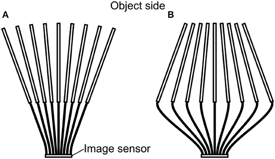
Figure 13. (A) The original arrangement in the presented prototypes where the tubes diverge, with the tubes directed to the object side at the top. For clarity, the grids are not shown. (B) A converging arrangement for potential use in a microscope. In this mode the angle β is negative.
Another option for introducing the zooming feature is depicted in Figure 14 (cf. Lee et al., 2018). This feature works without fibers. The image sensor in this case is flexible, and a lens is attached in front of each pixel, so that only close-to-parallel light enters each image sensor pixel. Bending the flexible sensor alters the angles between the axis of the individual light rays (comparable to angle β), yielding the zooming feature. Floreano et al. (2013) demonstrated the possibility for producing flexible optical arrays; here the curvature can be changed to enable zooming. This kind of zooming, however, does not allow for changing angle α.

Figure 14. Another possibility for a zooming feature is a flexible image sensor, depicted at the bottom; it can be equipped with tiny lenses, each focusing on a single pixel on the image sensor. (A) Flat sensor. (B) When spherically bent (convex or concave), the angle of light entering can be changed, which corresponds to angle β.
Another type of zooming feature, was implemented in an engineered system by combining a variable focal length liquid lens with an artificial compound eye imaging system; this also helped avoid an additional focusing mechanism (Duparré et al., 2008). Interesting in this regard is that spiders can change their visual fields via muscles acting on the retina; in the example provided, the visual angle can be changed from 10 to 58° (Foelix, 2011: Figure 4.21).
Such a flexibility feature can also be useful for optically scanning uneven or fragile surfaces such as old books that should not be opened too wide. The device would simply be placed on the page, and its flexibility would self-adjust to unevenness. Illumination might be integrated in the floppy scanner.
As known from video conferences via the computer screen, the web camera is located at a different place than where the partner's face appears on the screen. The new facet optics, being based on an array of single pixels, could be directly added in hardware to the pixels of the computer screen. In making the call, we could look directly into the eyes of the person we are talking with and vice-versa.
3D Printing Challenges
3D printing was advantageously used for prototyping. Market-ready products can be produced by other means. If, however, 3D printers are used in further stages of development as well, certain improvements need to be made toward further miniaturization. Thin fibers are readily available and, for them, tubes with small inner diameters need to be produced. Importantly, superfluous resin must leave the tubes. In incorrectly oriented tubes, in test prints of the facet optics, excess resin could not drain and subsequently clogged the tubes. Furthermore, the small structures of the printed prototype 2 made proper UV-curing a challenge. Incomplete UV-curing left unpolymerized resin on the surface and significantly increased the friction between the tubes and the movable grid. Some prints also deformed while UV-curing due to inhomogeneous shrinkage of the material. Further developments in 3D printers will certainly address miniaturization challenges.
Another challenge was finding the proper shapes for a given material. Tubes broke when the wall-thickness was too small, but were too stiff when it was too high. The tubes must be stiff enough to allow repeated movement of the movable grid to reproduce the angle β settings in an actuated device, where friction is also a consideration. Hence, materials with a lower tensile modulus are only a limited option. The material can also be expected to become brittle over time. The proper wall-thickness must be determined in an iterative process. The contact points between the object and the support structures had to be large enough to support the weight but small enough not to damage the object upon removing the support structures. This issue will no doubt also be addressed in future 3D-printing developments.
In summary, the combination of bio-inspired and new technical features yields new facet optics that will prove to be useful in a variety of specific applications, paving the ground for further advances. 3D printing was a valuable tool to demonstrate that the bio-inspired device works as expected when transferring principles from insects to engineering.
Conclusion
In this article, the development of prototypes for a new bio-inspired optical system was described. Based on the advantageous aspect of insect eyes that do not need focusing on objects, the aim of this work was to introduce two adjustable features: an adjustable field of view per pixel and a zooming possibility. Prototypes with tubes and acrylic fibers were used, arranged similarly to the biological concept generator. By varying the distance between tube end and fiber end, an adjustable field of view was achieved. Zooming was realized by adjusting the angle between individual tubes. In tests, the proof of concept for both features was provided. 3D printing using stereolithography was shown to be an efficient way of rapid prototyping. Challenges were: resin clogging the tubes, incomplete UV-curing and tubes breaking. When miniaturizing in future developments, it is questionable whether 3D printing is a proper tool.
Data Availability Statement
The datasets generated for this study are available on request to the corresponding author.
Author Contributions
MD: basic idea and realized prototype 1. AB: scientific coworker on 3D-printed facet optics (focused on technical aspects), realized test prints, and prototype 2. BE: scientific coworker on 3D-printed facet optics (focused on biological aspects), realized test prints, and prototype 2. IG: supervision of scientific coworkers. Manuscript writing was done together under the lead of MD. All authors contributed to the article and approved the submitted version.
Funding
The research of IG, AB, and BE was funded by the TU Center of Excellence for Biomimetics. Research of MD was funded by the Austrian Science Fund (FWF): P22955-G17 and the German Research Foundation (DFG) as part of the Transregional Collaborative Research Centre (SFB/Transregio) 141 ‘Biological Design and Integrative Structures’/project C02 ‘Organism concepts in biology and architecture as the basis for an interdisciplinary synopsis of constructional biomimetics.’ The authors thank TU Wien for covering open access publication fees.
Conflict of Interest
The authors declare that the research was conducted in the absence of any commercial or financial relationships that could be construed as a potential conflict of interest.
Acknowledgments
We thank Stefan Fischer (Evolutionary Biology of Invertebrates, University of Tübingen) for many useful hints and discussions. Thanks also goes to Stephan Handschuh (VetCore Facility for Research, Imaging Unit, University of Veterinary Medicine, Vienna) for providing Figure 2. PH Palden GmbH provided the acrylic fibers for the prototype. Thanks to Peter Purgathofer and Florian Holzner (Human Computer Interaction Group) of the Institute for Design and Assessment of Technology at the Technical University of Vienna for providing access to 3D printers.
References
Cheng, Y., Cao, J., Zhang, Y., and Hao, Q. (2019). Review of state-of-the-art artificial compound eye imaging systems. Bioinspir. Biomim. 14:031002. doi: 10.1088/1748-3190/aaffb5
Drack, M., Limpinsel, M., de Bruyn, G., Nebelsick, J. H., and Betz, O. (2018). Towards a theoretical clarification of biomimetics using conceptual tools from engineering design. Bioinspir. Biomim. 13:016007. doi: 10.1088/1748-3190/aa967c
Duparré, J. W., Wippermann, F., Dannberg, P., and Bräuer, A. (2008). Artificial compound eye zoom camera. Bioinspir. Biomim. 3:046008. doi: 10.1088/1748-3182/3/4/046008
Duparré, J. W., and Wippermann, F. C. (2006). Micro-optical artificial compound eyes. Bioinspir. Biomim. 1, R1–16. doi: 10.1088/1748-3182/1/1/R01
Exner, S. (1891). “Die Physiologie der facettierten Augen von Krebsen und Insecten,” (Leipzig: Deuticke). Translated as: The Physiology of the Compound Eyes of Insects and Crustaceans, ed R. C. Hardie (Berlin: Springer), 1989. doi: 10.5962/bhl.title.2149
Fiberguide Industries (2017). Anhydrous silica (ASI) single mode fiber. Available online at: https://www.fiberguide.com/wp-content/uploads/2013/03/ASI_030713.pdf (accessed December 30, 2019).
Floreano, D., Pericet-Camara, R., Viollet, S., Ruffier, F., Brückner, A., Leitel, R., et al. (2013). Miniature curved artificial compound eyes. PNAS 110, 9267–9272. doi: 10.1073/pnas.1219068110
Formlabs (2017). Materials Data Sheet. Available online at: www.formlabs.com/media/upload/XL-DataSheet.pdf (accessed January 14, 2018).
Gibson, I., Rosen, D., and Stucker, B. (2015). Additive Manufacturing Technologies: 3D Printing, Rapid Prototyping, and Direct Digital Manufacturing, 2nd Edn. New York, NY: Springer. doi: 10.1007/978-1-4939-2113-3
Jeong, K. H., Kim, J., and Lee, L. P. (2006). Biologically inspired artificial compound eyes. Science 312, 557–561. doi: 10.1126/science.1123053
Kirschfeld, K. (1976). “The resolution of lenses and compund eyes,” in: Neural Principles in Vision, eds F. Zettler and R. Weiler (Berlin: Springer), 354–370. doi: 10.1007/978-3-642-66432-8_19
Kirschfeld, K. (2001). “Photorezeption (periphere Sehorgane),” in: Neurowissenschaften – Vom Molekül zur Kognition, eds J. Dudel, R. Menzel, and R. F. Schmidt (Berlin: Springer), 385–405. doi: 10.1007/978-3-642-56497-0_17
Lakshminarayanan, V., and Parthasarathy, M. K. (2016). Biomimetic optics: visual systems. J. Modern Optics. 9, 1–26. doi: 10.1080/09500340.2016.1224939
Land, M. F., and Nilsson, D.-E. (2012). Animal Eyes. Oxford, UK: Oxford University Press. doi: 10.1093/acprof:oso/9780199581139.001.0001
Lee, G. J., Choi, C., Kim, D.-H., and Song, Y. M. (2018). Bioinspired artificial eyes: optic components, digital cameras, and visual prostheses. Adv. Funct. Mater. 28:1705202. doi: 10.1002/adfm.201705202
Lee, L. P., and Szema, R. (2005). Inspirations from biological optics for advanced photonic systems. Science 310, 1148–1150. doi: 10.1126/science.1115248
Meyer-Rochow, V. B. (1999). “III-2 compound eye: circadian rhythmicity, illumination, and obscurity,” in: Atlas or Arthropod Sensory Receptors, eds E. Eguchi and Y. Tominaga (Berlin: Springer), 97–125.
Narendra, A., Alkaladi, A., Raderschall, C. A., Robson, S. K., and Ribi, W. A. (2013). Compound eye adaptations for diurnal and nocturnal lifestyle in the intertidal ant, Polyrhachis sokolova. PLoS ONE 8:e76015. doi: 10.1371/annotation/b18fcad6-597e-4ba9-86bc-f21030ed3a1b
Nilsson, D.-E. (1989). “Optics and evolution of the compound eye,” in: Facets of Vision, eds D. G. Stavenga and R. C. Hardie (Berlin: Springer), 30–73. doi: 10.1007/978-3-642-74082-4_3
Schott (2020). General Specifications. Available online at: https://www.schott.com/lightingimaging/english/sensors/products/coldvision/specifications.html (accessed June 26, 2020).
Song, Y. M., Park, H. G., Lee, G. J., and Park, J. S. (2017). “Artificially engineered compound eye sensing systems,” in: Smart Sensors and Systems, eds C. M. Kyung, H. Yasuura, Y. Liu, and Y. L. Lin (Cham: Springer), 157–174. doi: 10.1007/978-3-319-33201-7_7
Warrant, E. J., and McIntyre, P. D. (1993). Arthropod eye design and the physical limits to spatial resolving power. Prog. Neurobiol. 40, 413–461. doi: 10.1016/0301-0082(93)90017-M
Keywords: apposition compound eyes, biomimetics, bioinspiration, imaging, fiber optics, zooming, field of view
Citation: Drack M, Berger A, Ettinger B and Gebeshuber IC (2020) 3D-Printed Facet Optics: Novel Adjustable Technical Optics Inspired by Compound Eyes. Front. Mater. 7:199. doi: 10.3389/fmats.2020.00199
Received: 28 January 2020; Accepted: 29 May 2020;
Published: 24 July 2020.
Edited by:
Chi Zhou, University at Buffalo, United StatesReviewed by:
Antonio Greco, University of Salento, ItalyAbu Zayed M. Saliqur Rahman, The Ohio State University, United States
Copyright © 2020 Drack, Berger, Ettinger and Gebeshuber. This is an open-access article distributed under the terms of the Creative Commons Attribution License (CC BY). The use, distribution or reproduction in other forums is permitted, provided the original author(s) and the copyright owner(s) are credited and that the original publication in this journal is cited, in accordance with accepted academic practice. No use, distribution or reproduction is permitted which does not comply with these terms.
*Correspondence: Ille C. Gebeshuber, Z2ViZXNodWJlckBpYXAudHV3aWVuLmFjLmF0
 Manfred Drack1
 Alexander Berger
 Bernhard Ettinger
 Ille C. Gebeshuber