 Wei-Min Zhong1
 An-Ding Zhu
 Xian-Xu Frank Bai
 Norman M. Wereley
- 1Laboratory for Adaptive Structures and Intelligent Systems (LASIS), Department of Vehicle Engineering, Hefei University of Technology, Hefei, China
- 2Smart Structures Laboratory, Department of Aerospace Engineering, University of Maryland, College Park, MD, United States
Inerter is a two-terminal mass element, and the applied force is proportional to the relative acceleration between the terminals. According to the second class of mechanical–electrical analogy, the inerter corresponds exactly to the capacitor in the electric network. Aiming at improving the limited vibration isolation performance using the constant inertance of a conventional inerter, a new semi-active inerter based on smart material, magnetorheological (MR) fluid, is proposed in this paper. Furthermore, according to the design concept of “functional integration”, the MR inerter, an MR damper, and a spiral spring are integrated to realize a new integrated inerter-spring-damper (IISD) with both adjustable inertance and damping characteristics. The MR inerter consists of a ball screw, an MR clutch, MR fluid, excitation coils, an excitation shell, a flywheel, a flywheel shell, a connector, upper and lower covers, bearings, and seals. The tunable inertance is achieved by adjusting the excitation current in the excitation coils to change the operating state of the MR clutch. The MR damper and the spiral spring provide variable damping and constant stiffness, respectively. The mathematical model of the IISD is established. The adjustment principle of inertance is verified by numerical simulation, and the mechanical output characteristics of the IISD are analyzed. Besides that, the 1/4 vehicle suspension model based on the proposed IISD is built by using MATLAB/SimMechanics. The frequency response and the unit impulse response characteristics of the suspension are obtained via the comfort-oriented virtual experiment. The simulation results show that the suspension with the IISD has 23.0% higher performance than the conventional suspension in vehicle body acceleration, and the suspension deflection and the dynamic tire load are also improved.
Introduction
According to the first class of mechanical–electrical analogy, the mass, spring, and damper in the mechanical network correspond to the capacitor, inductance, and resistance in the electric network, respectively. Meanwhile, Newton’s Second Law states that the applied force is proportional to the absolute acceleration of mass, i.e., mechanical grounded. Therefore, the mass can only correspond to the grounded capacitor, which greatly limits the application of the method applied to electrical circuits in a mechanical network design. In response to the above problem, in 2002, a new mass element termed “inerter” was introduced by Smith (2002) according to the second class of mechanical–electrical analogy, which completely corresponds to the capacitor in an electrical network. The inerter has two movable terminals, and the applied force is proportional to the relative acceleration between its terminals. There is no longer a “ground” limitation during the mechanical network design by using the electric method, which greatly enriches the structure and the design ideas of the mechanical network. The performance of vibration control systems based on inerter is further improved compared to the mass–spring–damper system. At the same time, the inerter has smaller volume and weight than the traditional mass element. Therefore, the inerter has received extensive attention from researchers in different fields (Smith and Wang, 2004; Papageorgiou and Smith, 2006; Chen et al., 2009; Papageorgiou et al., 2009; Brzeski et al., 2015; Matamoros-Sanchez and Goodall, 2015; Giaralis and Petrini, 2017).
The vibration isolation performance of the passive inerter is limited because of the fixed inertance. Different types of semi-active inerter have been introduced recently. Hu et al. (2016) proposed a mechanical adjustable inerter that is mainly composed of mass blocks sliding along the radial direction and a linear actuator. The linear actuator can change the radius of gyration of the mass, that is, continuous adjustment of the inertance can be achieved by changing the rotational inertia of the flywheel. The use of magnetorheological (MR) fluid to achieve an adjustable inerter has also been preliminarily studied. Tipuric et al. (2018) studied the feasibility of a spiral-tube semi-active inerter based on MR fluid. Bai et al. (2018) extended a semi-active inerter concept using MR fluid, while its feasibility has not been verified. We later proposed a tunable inerter based on MR fluid (Zhong et al., 2019); however, an additional force compensation mechanism is needed to achieve a continuous adjustment of the inertance.
Although the inertance of the existing semi-active inerters can be adjusted by different ways, there is still potential to improve the adjustment speed and extend the range of inertance. A tunable inerter with a wide adjustment range, fast response, and low energy consumption needs to be developed. In the field of semi-active control, MR fluid has exactly the above properties. At present, the intelligent actuators based on MR fluid have been thoroughly studied in many fields (Imaduddin et al., 2013; Kaluvan et al., 2015; Bai et al., 2016; Sapiñski et al., 2016; Shiao et al., 2016). Nevertheless, applying the MR fluid to semi-active inerter and inerter–spring–damper (ISD) vibration isolation systems it is still preliminary. Based on the concept of “functional integration” (Bai et al., 2017), this paper proposes an adjustable inerter. The MR inerter, an MR damper, and a spiral spring are highly integrated to realize the integrated ISD (IISD) with a compact structure, quick response, and wide adjustment range. Besides that, the 1/4 vehicle suspension model with the IISD is built by using MATLAB/SimMechanics, and virtual experiment was carried out to validate the performance.
Structural Principle of the IISD
Integrated Design
The connection between the MR inerter, MR damper, and spiral spring should be considered during the integrated design procedure. The integrated layout of the IISD is demonstrated in Figure 1. The spiral spring acts as a support, and the inerter in series with the damper can provide better performance than that of the parallel form (Smith and Wang, 2004). The MR inerter and the MR damper have a common terminal, and the other two terminals are connected to the ends of the spiral spring, respectively. The spring in parallel with the MR damper in Figure 1 refers to the accumulator inside the MR damper (see Figure 3).
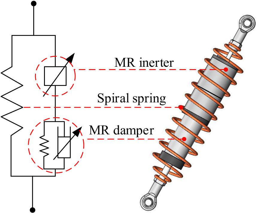
Figure 1. Schematic of the integrated inerter-spring-damper.
MR Inerter
The structural principle of the MR inerter is shown in Figure 2. The MR inerter consists of a ball screw, an MR clutch, MR fluid, excitation coils, an excitation shell, a flywheel, a flywheel shell, a connector, upper and lower covers, bearings, and seals. The inner casing of the MR clutch is connected to the nut of the ball screw. The outer casing of the MR clutch is engaged with the flywheel, and the excitation coils are winded on the excitation shell around the MR clutch. The space between the inner and the outer casings of the MR clutch is filled with MR fluid, which is working under pure shear mode. When a displacement excitation is applied to the terminals of the MR inerter, the inner casing of the MR clutch rotates with the nut of the ball screw. When there is no current in the excitation coils, the outer and the inner casing of the MR clutch are completely disconnected, and the output force of the MR inerter is independent of the flywheel. When a certain current is applied, the rotating inner casing of the MR clutch will rotate the outer casing for the effect of the MR fluid, i.e., rotate the flywheel. The nut on the ball screw receives additional torque from the flywheel due to the effect of the additional mass, and additional inertance can be provided. The complete disengagement and engagement of the MR clutch correspond to the minimal and the maximal inertance, respectively.
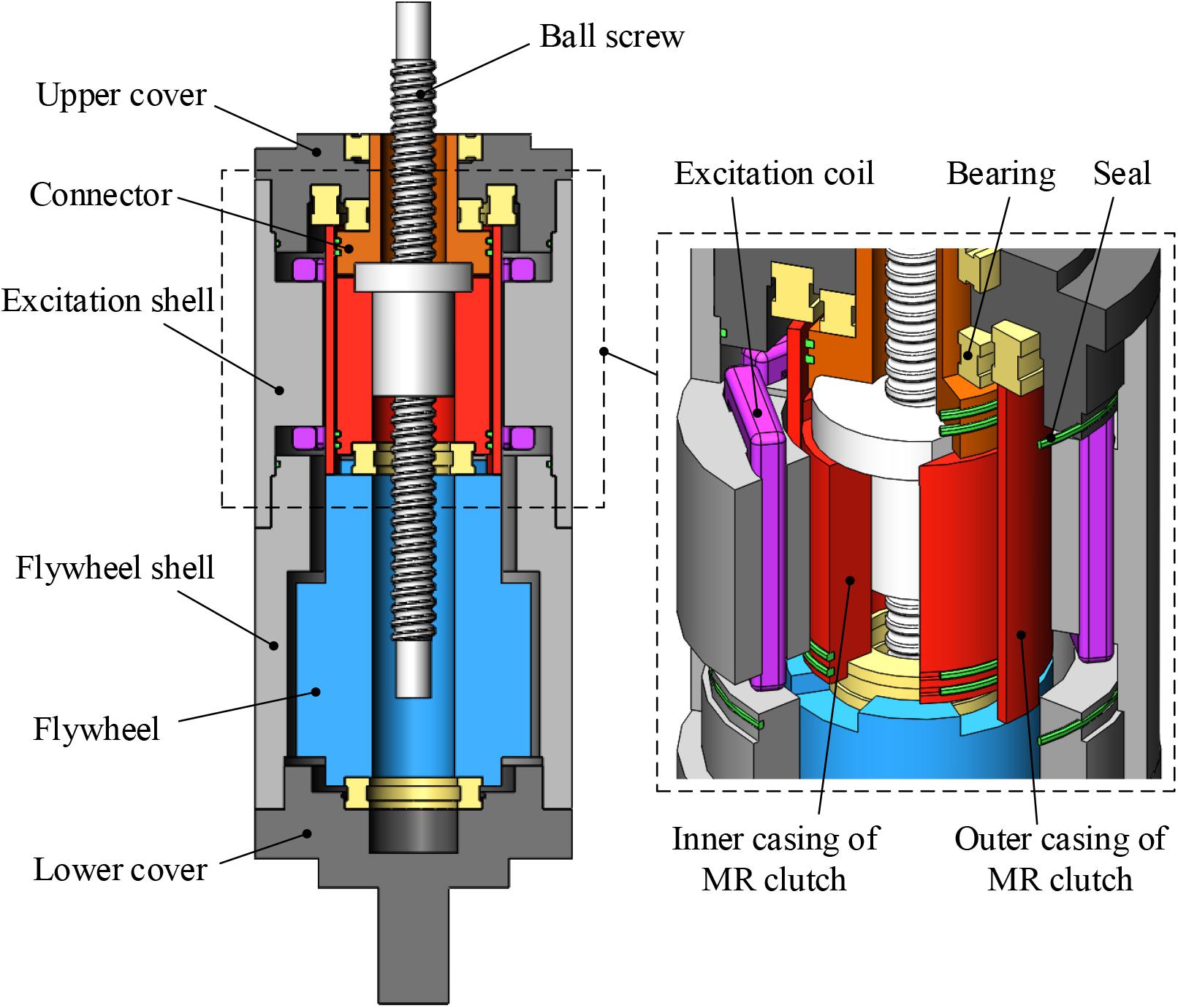
Figure 2. Structural principle of the magnetorheological inerter.
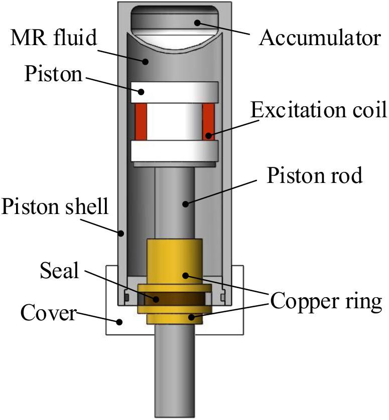
Figure 3. Structural principle of the magnetorheological damper.
MR Damper
Figure 3 demonstrates the structural principle of the MR damper. The MR damper mainly includes a piston, a piston rod, excitation coils, MR fluid, an accumulator, a piston shell, a cover, copper rings, and a seal. The viscosity of the MR fluid can be changed by adjusting the current in the excitation coils; thereby, the damping coefficient of the MR damper can be adjusted.
Mathematical Model of the IISD
As shown in Figure 4, the output force of the IISD is related to four factors, i.e., the spring stiffness k, the inertance b of the MR inerter, the damping coefficient c of the MR damper, and the accumulator stiffness ka. Since the MR inerter is connected in series with the MR damper, and the accumulator is connected in parallel with the MR damper, the output force of the MR inerter is equal to the sum of the output forces of the MR damper and the accumulator, and then the output force of the IISD can be expressed as:
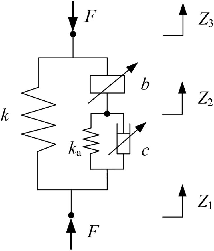
Figure 4. Mechanical model of the integrated inerter-spring-damper.
where Z1 and Z3 are the displacement at the terminals of the spiral spring, Z2 is the displacement at the junction of the MR damper and the MR inerter, Ż1 and Ż2 are the velocity at the terminals of the MR damper, and and are the acceleration at the terminals of the MR inerter.
The proposed MR inerter is designed based on ball-screw type and its inertance b can be expressed as (Wang and Chan, 2008):
where J is the moment of inertia of the flywheel and p is the lead of the ball-screw.
According to the principle analysis of the MR inerter, the completely disengaged and engaged states of the MR clutch corresponding to the minimal and the maximal inertance, respectively, can be expressed as:
where J1 is the moment of inertia of the inner casing of the MR clutch and J2 is the sum of the moments of inertia of the outer casing of the MR clutch and the flywheel.
It can be seen from Eq. (3) that the minimal and the maximal inertances of the MR inerter are only dependent on the parameters of the structure itself. So, the adjustment range of the inertance is determined by the geometry of the structure. The inertance between the minimal and the maximal can be obtained by controlling the MR clutch.
Figure 5 shows a simplified model of the MR clutch. The angular velocity of the inner and the outer casings of the MR clutch is ω1 and ω2, respectively. Under an ideal condition (i.e., the MR clutch can be completely disengaged and engaged), the relationship between the angular velocities of the inner and the outer casings of the MR clutch corresponding to the minimal inertance is . The relationship of the maximal inertance refers to . Any intertance between the minimal and the maximal can be reached by setting the ratio of the outer casing to the inner casing angular velocity of the MR clutch between 0 and 1. Since the angular velocity of the inner casing of the MR clutch is generated by external excitation, the problem of adjusting the inertance is actually transformed into the control of the angular velocity of the outer casing.
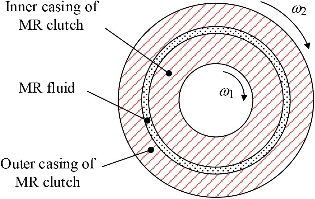
Figure 5. Simplified model of the magnetorheological clutch.
The output force Fi of the MR inerter depends on the torque applied on the nut of the ball-screw. The torque consists of two parts, i.e., the torque generated by the inner casing of the MR clutch and the additional torque generated by the rotation of the flywheel, which can be expressed as:
where is the angular acceleration of the inner casing of the MR clutch and is the angular acceleration of the outer casing of the MR clutch, i.e., the angular acceleration of the flywheel.
Defining , then Eq. (5) can be rewritten as:
The inertance can be obtained simultaneously from Eqs (1, 4, and 6), and :
From Eq. (7), any inertance between the minimal and the maximal can be achieved by adjusting the proportional coefficient γ.
The torque TMR transmitted by the MR clutch equals to the additional torque Te acting on the nut of the ball-screw, which consists of two parts: one is the uncontrollable torque Tη caused by the viscous force due to the different angular velocity between the inner and the outer casings of the MR clutch, and the other one is the controllable torque Tτ caused by the shear stress under the effect of the magnetic field. They can be respectively expressed as:
where η is the viscosity of the MR fluid without magnetic field, Lc is the effective length of the MR fluid in the MR clutch, r1 and r2 are the inner and the outer radius of the annular gap filled with the MR fluid, respectively, and τy is the yield shear stress of the MR fluid under the effect of the magnetic field.
Replacing the TMR in Eq. (8a) with the load torque TL, the angular velocity of the outer casing of the MR clutch can be obtained:
Numerical Simulation
Table A1 presents a list of the main structural parameters of IISD. According to the parameters in Table A1, under an ideal situation, the adjustment range of the inertance that can be realized by the MR inerter is shown in Figure 6. The minimal inertance is 86 kg and the maximal inertance is 927 kg. In the process of the change of the proportional coefficient γ from 0 to 1, the inertance experiences a proportional increase.
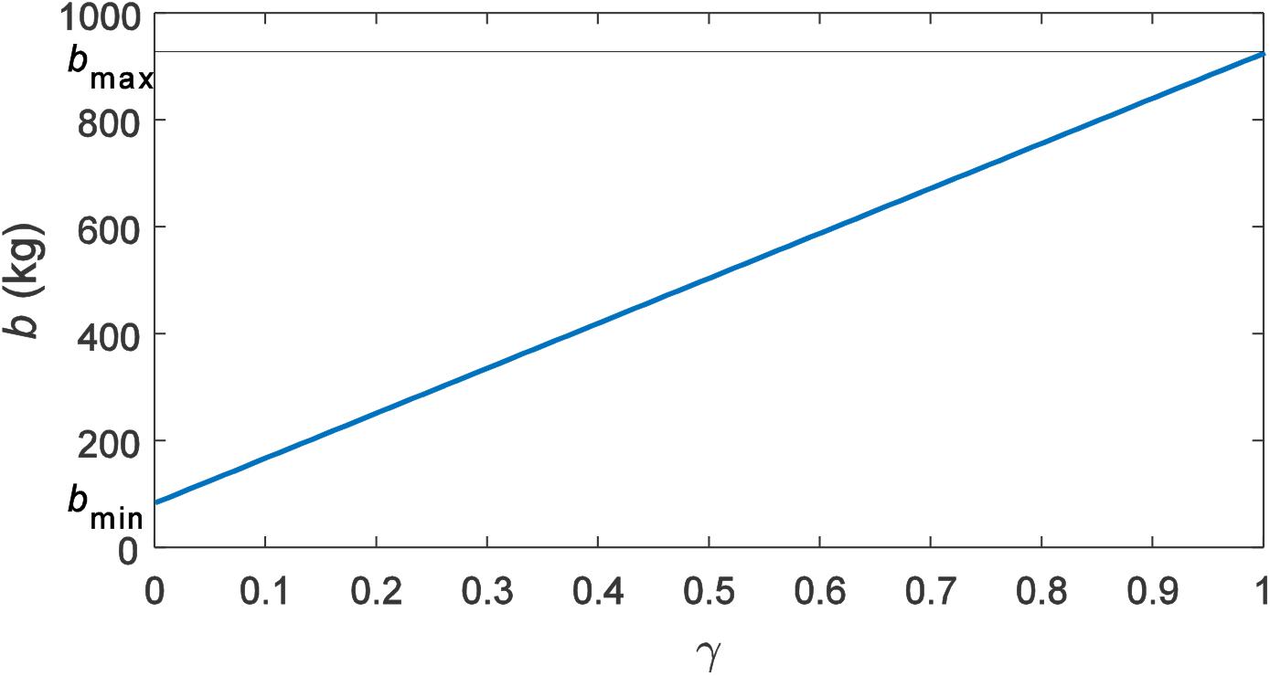
Figure 6. Adjustment process of the inertance under an ideal situation.
Although the adjustment range and change trend of inertance can be observed under an ideal situation, the actual torque of the MR clutch and whether continuous adjustment can be achieved are not known. In order to further verify the adjustment principle of the inertance, a simulation is performed by applying a certain displacement excitation to the MR inerter. The displacement excitation has an amplitude of 20 mm and a frequency of 0.5 Hz. The simulation condition is set as adjusting the inertance from the minimal to the maximal within 0.5 s to observe the changes of the expected additional torque Te, the uncontrollable torque Tη, and the controllable torque Tτ. The simulation results are shown in Figure 7.
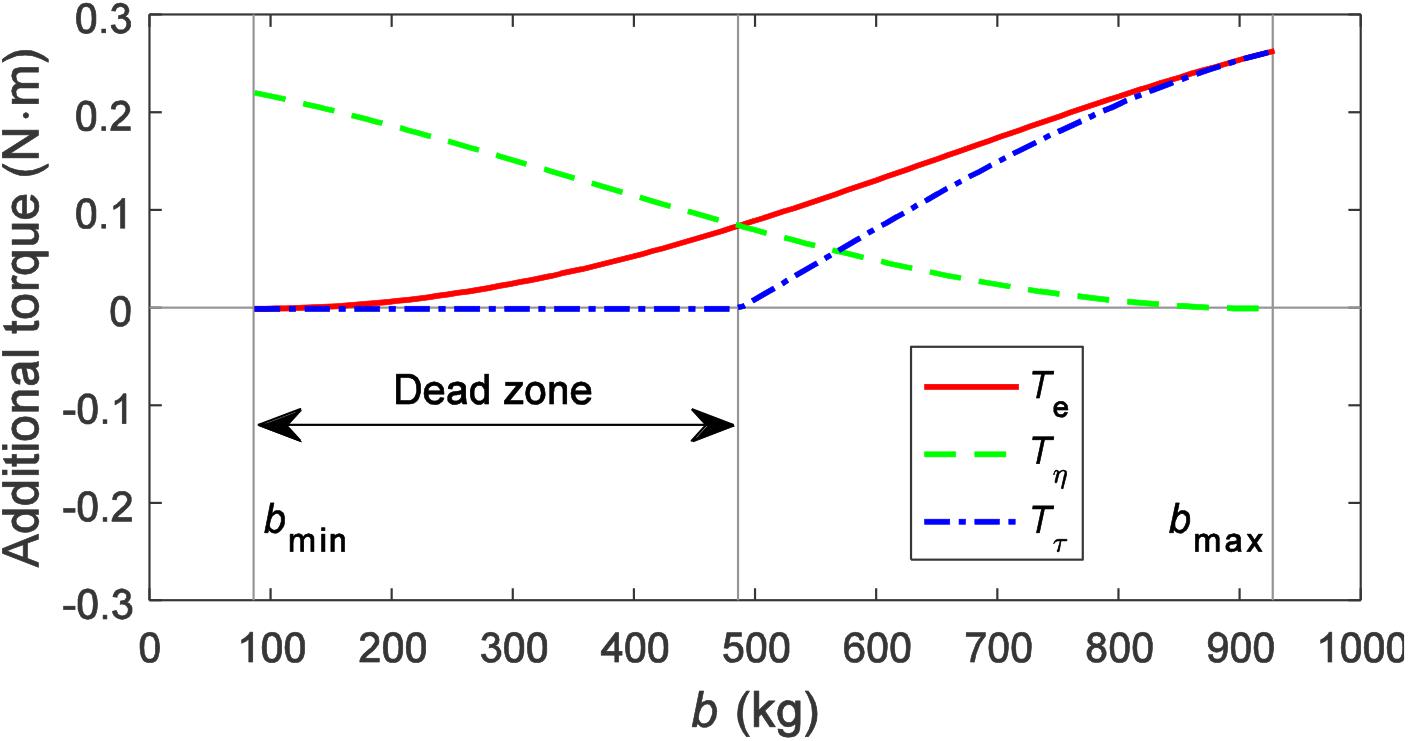
Figure 7. Additional torque during the adjustment of the inertance.
It can be seen from Figure 7 that, as the inertance increases, the expected additional torque is continuously increased from 0 Nm to about 0.26 Nm. During the increase of the inertance, the rotational velocity of the inner and the outer casings of the MR clutch is gradually getting close until eventually synchronous; the uncontrollable torque Tη is gradually reduced from about 0.22 to 0 Nm. The controllable torque Tτ is 0 Nm before the inertance of 486 kg, after which it gradually fits with the expected additional torque Te and finally increases to about 0.26 Nm. The process of adjusting the inertance is actually the process of controlling the torque generated by the MR clutch to track the expected additional torque. Since the torque generated by the MR clutch contains uncontrollable torque, when the expected additional torque is less than the uncontrollable torque, the MR clutch can no longer provide less torque, i.e., the expected additional torque cannot be tracked. In this situation, the expected additional torque can only be replaced by the uncontrollable torque. The range of which the expected additional torque is less than the uncontrollable torque is defined as the “dead zone”. Therefore, the controllable torque of 0 Nm in Figure 7 is explained. When the expected additional torque is greater than the uncontrollable torque, a controllable torque will be generated to compensate for the difference between them so that the torque produced by the MR clutch can reach the expected additional torque.
The existence of the dead zone reduces the adjustment range of the inertance. Although the dead zone is unavoidable due to the existence of uncontrollable torque, its interval can be shortened. Observing Equation (8b), it can be seen that, when the gap width of the MR clutch casings ΔL = r2−r1 is increased, the uncontrollable torque will decrease. Therefore, the range of the dead zone can be reduced by changing the structural parameters of the MR clutch. The gap widths of the MR clutch casings are selected as ΔL1 = 1mm, ΔL2 = 5mm, and ΔL3 = 10mm as simulation parameters, and the simulation results are shown in Figure 8.
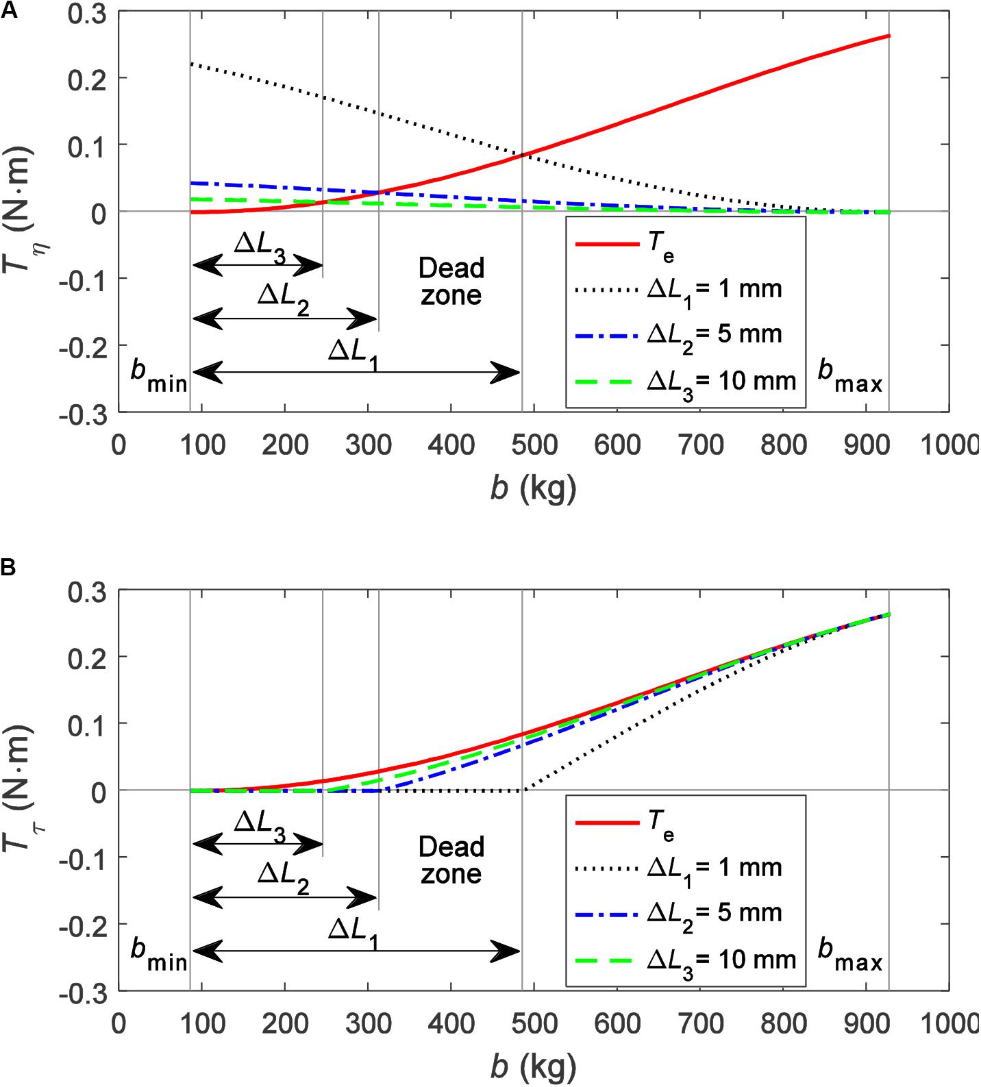
Figure 8. Additional torque under different gap widths: (A) uncontrollable torque and (B) controllable torque.
As shown in Figure 8A, as the gap width increases, the uncontrollable torque decreases significantly, and the dead zone is obviously shortened. Observing Figure 8B, the controllable torque becomes closer to the expected additional torque throughout the adjustment range as the gap width increases. This demonstrates that the increasing gap width can effectively reduce the influence of the dead zone and improve the adjustment performance of the inertance.
Figure 9 shows the variation trends and ranges of the output force and the inertance of the MR inerter under different gap widths of the MR clutch. It can be seen from Figure 9 that, similar to the controllable torque, the output force and the inertance are getting closer to the expected output force Fe and the expected inertance be, respectively, as the gap width increases.
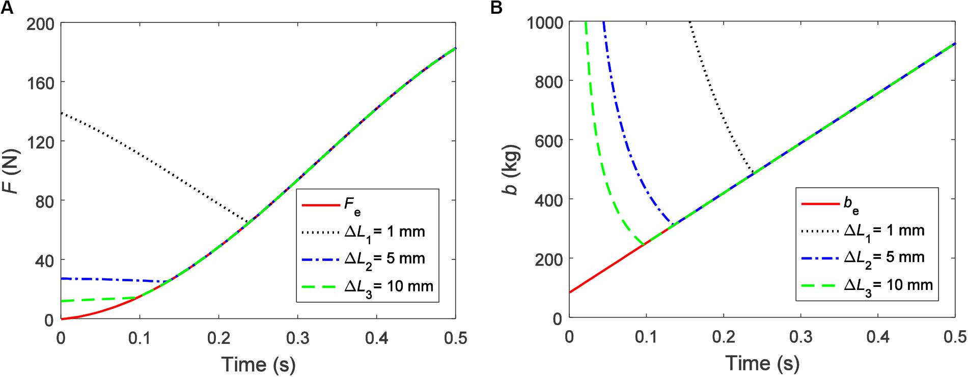
Figure 9. Output characteristics of the magnetorheological inerter under different gap widths: (A) force and (B) inertance.
In order to investigate the influence of different inertances and damping coefficients on the mechanical output characteristics of the IISD, sinusoidal displacement excitations, with an amplitude of 20 mm and a frequency of 1.0 Hz, are set as simulation parameters. The values of the inertance and the damping coefficient are uniformly selected from 200–800 kg and 1,000–7,000 N⋅s/m, respectively. The force–displacement characteristics and the force–velocity characteristics under different inertances (the damping coefficients are all 5,000 N⋅s/m) and damping coefficients (the inertances are all 200 kg) are shown in Figures 10, 11, respectively.
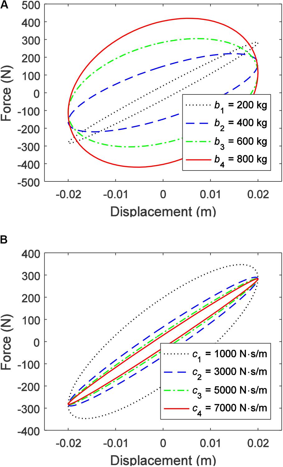
Figure 10. Force–displacement characteristics of the integrated inerter-spring-damper: (A) different inertances and (B) different damping coefficients.
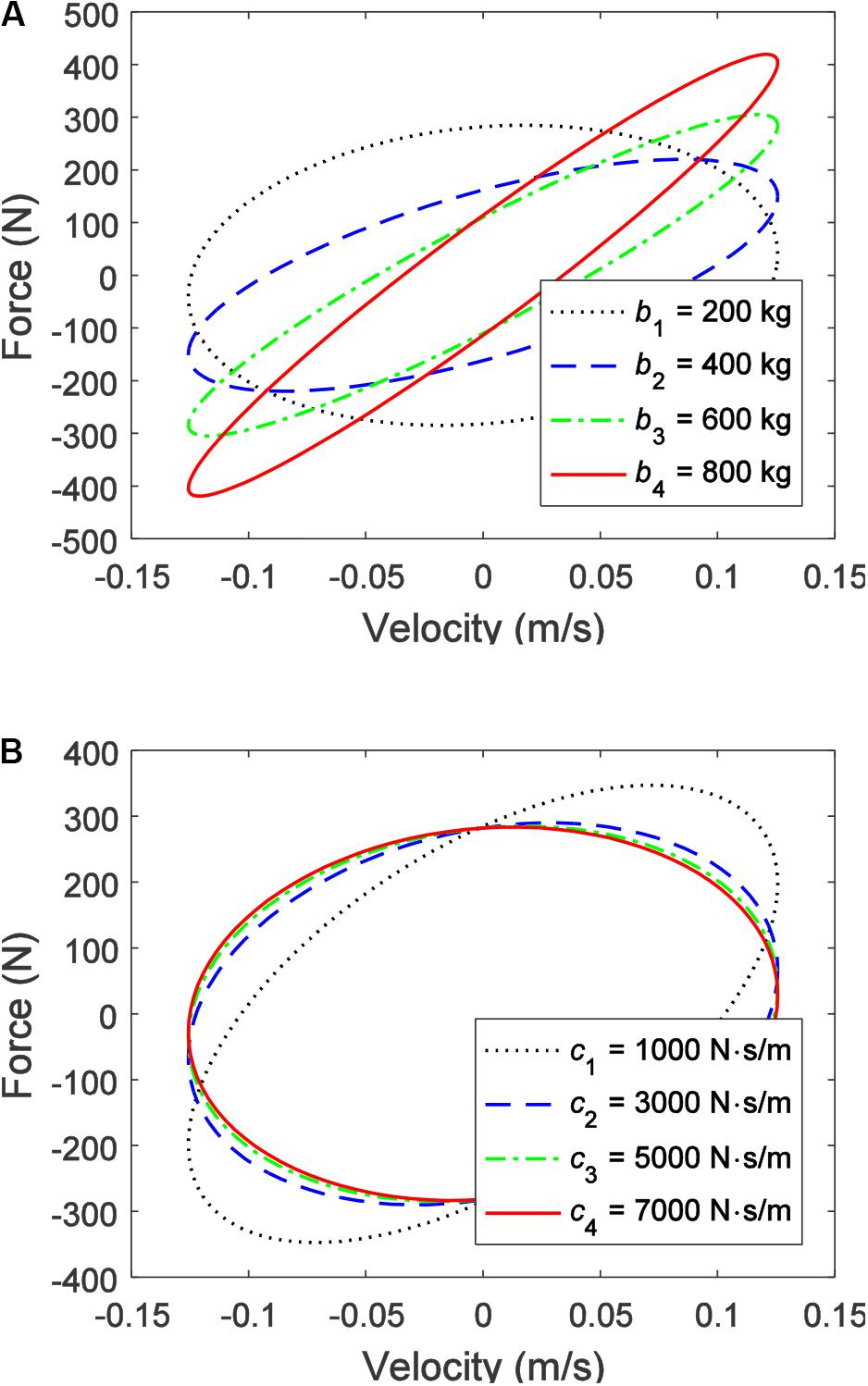
Figure 11. Force–velocity characteristics of the integrated inerter-spring-damper: (A) different inertances and (B) different damping coefficients.
As shown in Figure 10A, as the inertance increases, an obvious phase change of the output force of the IISD can be observed, and the value of the output force is increasing overall. In contrast, Figure 10B shows that different damping coefficients have less influence on the phase of the output force. Especially when the damping coefficient exceeds 5,000 N⋅s/m, the phase of the output force hardly changes. However, the larger the damping coefficient, the closer the ISD is to the linear device. A consistent conclusion can be obtained from the force–velocity characteristics shown in Figures 11A,B.
Virtual Experiment of 1/4 Vehicle Suspension With IISD
The 1/4 vehicle suspension with the IISD is built and virtually tested by using the software MATLAB/SimMechanics. The mechanical components are assembled into a 1/4 vehicle suspension by establishing a mutual position and connection relationship between each component in MATLAB/SimMechanics. The working status of the specific components can be detected in real time, such as displacement, velocity, acceleration, and force. The virtual experimental system is demonstrated in Figure A1, and the specific structural parameters are listed in Tables A1, A2 in the Appendix.
For the performance of semi-active suspension based on both tunable inertance and damping, the key factor is the selection of inertance and damping coefficient. Here the parameter optimization of the semi-active suspension is comfort-oriented, that is to say, the optimal inertance and the optimal damping coefficient should minimize the vehicle body acceleration. Since the minimal and the maximal inertance of the MR inerter are determined by the moment of inertia of the inner casing of the MR clutch and the flywheel, respectively, the adjustment range of the inertance can be expanded by the structural design. Similarly, the structural parameters of the MR damper determine the adjustment range of the damping coefficient. In order to observe the performance of the IISD under a large range of inertance and damping coefficient as well as provide reference for the structural design of MR inerter and MR damper, the inertance is selected between 0 and 5,000 kg and the damping coefficient is limited to 0–5000 N⋅s/m during the parameter optimization. The excitation conditions here are sinusoidal displacement signals with different frequencies. The optimization process is carried out by the MATLAB optimization toolbox and the result is shown in Figure 12.
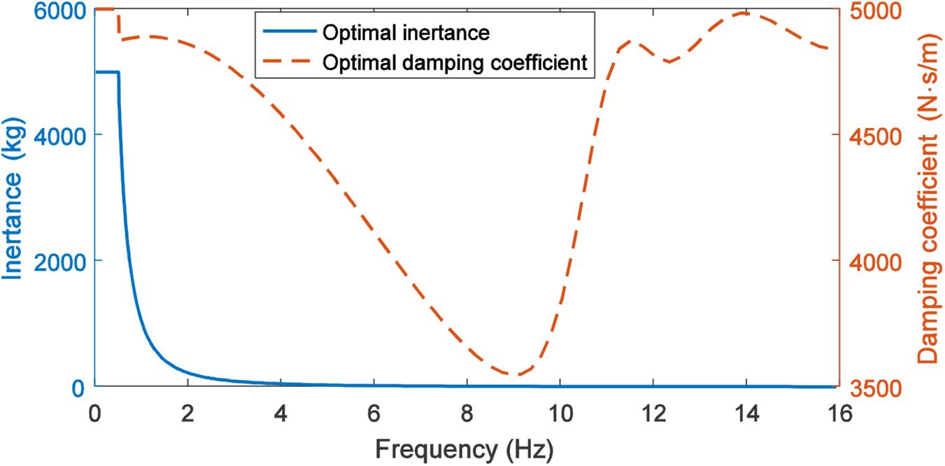
Figure 12. Optimal inertance and optimal damping coefficient.
The MR inerter controller is an adjustment module for the inertance, and selects the optimal inertance based on the excitation frequency. Similarly, the MR damper controller selects the optimal damping coefficient because this study uses a numerical simulation method, that is, the optimal inertance and the damping coefficient are obtained by sinusoidal displacement excitation at different frequencies. Therefore, the MR inerter and the MR damper controller here are not complicated. The MR inerter and the MR damper controller can be regarded as the correspondence between the optimal inertance and the damping coefficient and the excitation frequency, as shown in Eqs (10, 11), respectively.
where bopt, copt, and fe are optimal inertance, optimal damping coefficient, and excitation frequency, respectively.
In reality, the road excitation is unknown, and a method that identifies the frequency of excitation is needed. For the unsteady signal like road excitation, the commonly used methods include short-time Fourier transform and wavelet analysis. The performance of controllers, which outputs the optimal control parameters based on road excitation, will be tested in subsequent experimental studies.
Based on the optimal inertance and the optimal damping coefficient, the frequency response characteristics of the vehicle body acceleration, the suspension deflection, and the dynamic tire load are obtained as shown in Figure 13. Moreover, as likewise shown in Figure 13A, the vehicle body acceleration of the semi-active suspension has two peaks, which appear at 1.5 and 11 Hz, respectively. The frequency of 1.5 Hz is the first-order natural frequency of the suspension (i.e., the vehicle body resonance frequency), and the amplitude of the sprung mass at this frequency is much larger than the amplitude of the unsprung mass. The frequency of 11 Hz is the second-order natural frequency of the suspension (i.e., the tire resonance frequency). At this frequency, the amplitude of the unsprung mass is much larger than the amplitude of the sprung mass. As a result, vehicle body acceleration peaks at these two frequencies. The amplitude of the first-order natural frequency decreases significantly due to the large inertance. The amplitude of the second-order natural frequency is mainly related to the suspension parameters, which can be decreased by reducing the unsprung mass. It can be observed from Figures 13B,C that the suspension deflection is slightly decreased in the whole range of frequency, while the dynamic tire load is slightly deteriorated during 2–8 Hz.
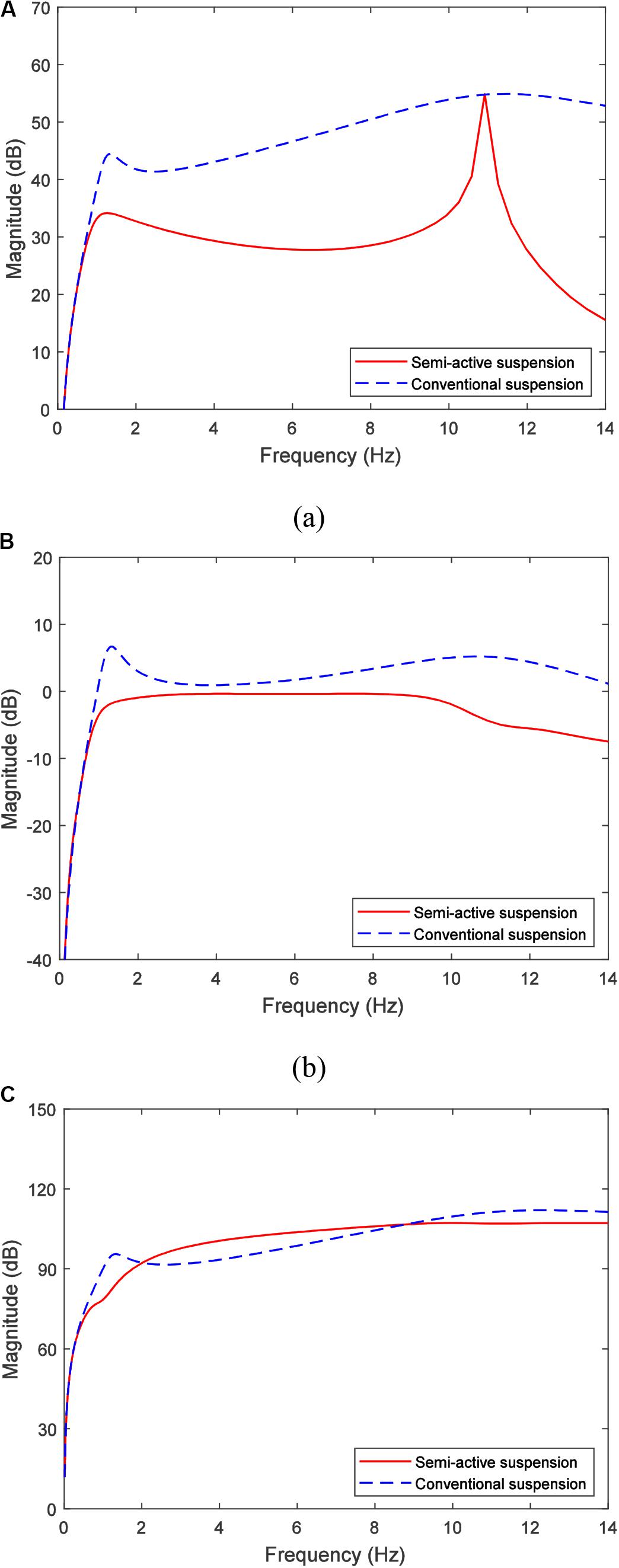
Figure 13. Frequency response of the 1/4 vehicle suspension: (A) vehicle body acceleration, (B) suspension deflection, and (C) dynamic tire load.
Figure 14 demonstrates the root mean square values for the different performances of the conventional suspension and the semi-active suspension. The simulation results show that the performance of the vehicle body acceleration of the semi-active suspension is significantly improved, which was by 23.0% compared with the conventional suspension. The performance of the suspension deflection and the dynamic tire load are slightly improved (0.8 and 1.1%, respectively), which is consistent with the comfort-oriented optimization goal.
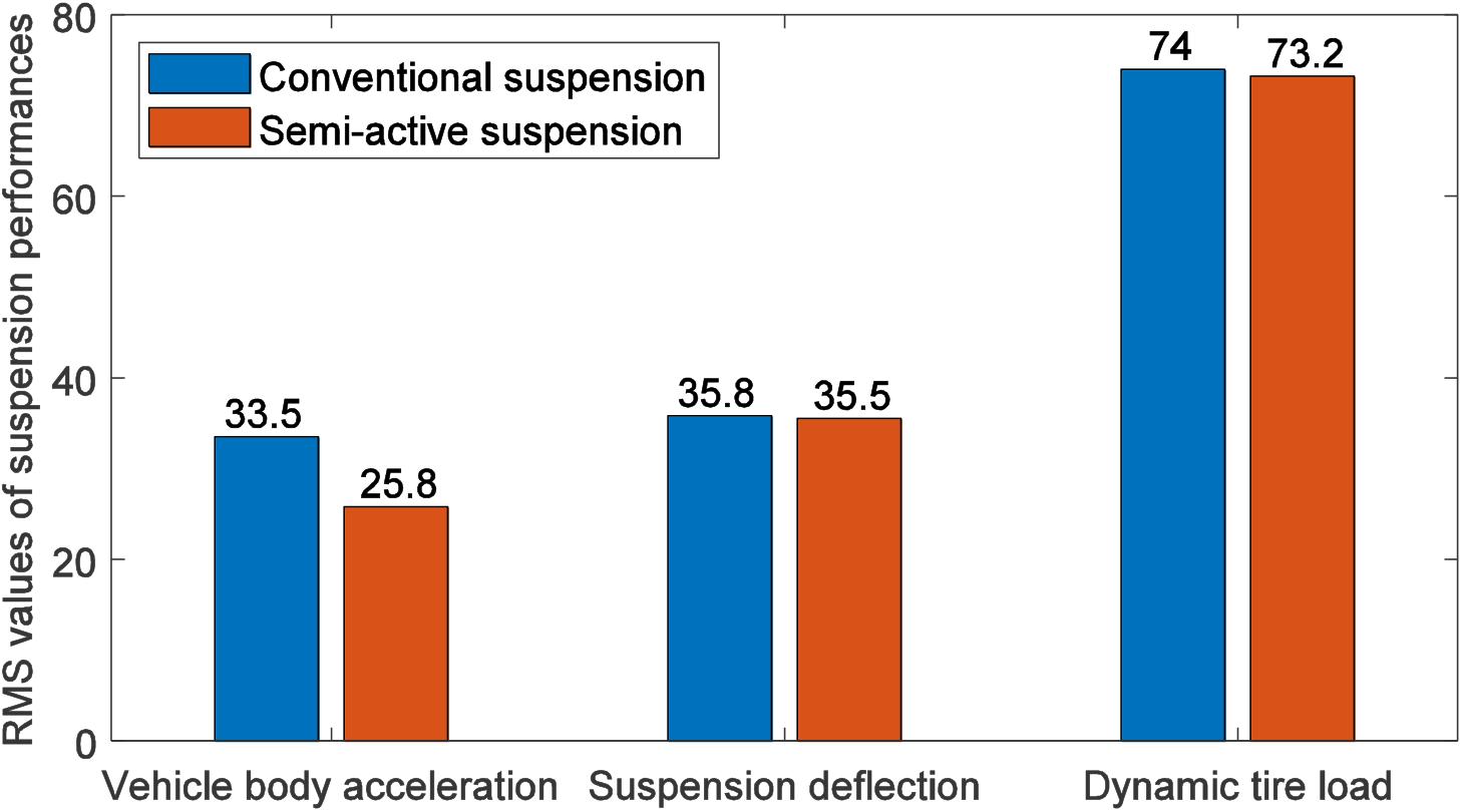
Figure 14. Root mean square values of the suspension performances.
The unit impulse responses of semi-active and conventional suspensions are shown in Figure 15. It can be seen from Figure 15A that, at the very beginning of the impulse response, the vehicle body acceleration of the semi-active suspension is slightly greater than that of the conventional suspension. This is because the impulse is an excitation generated in a very short time, which is equivalent to a very high frequency excitation, and this requires that the inertance must be very small. Due to the mass of the inerter flywheel, the inertance cannot be reduced indefinitely, so it is slightly deteriorated in the case of extremely high frequencies (i.e., the very beginning of the impulse response). The vehicle body acceleration of the semi-active suspension quickly stabilized in the subsequent period, while the conventional suspension lasted for a while.
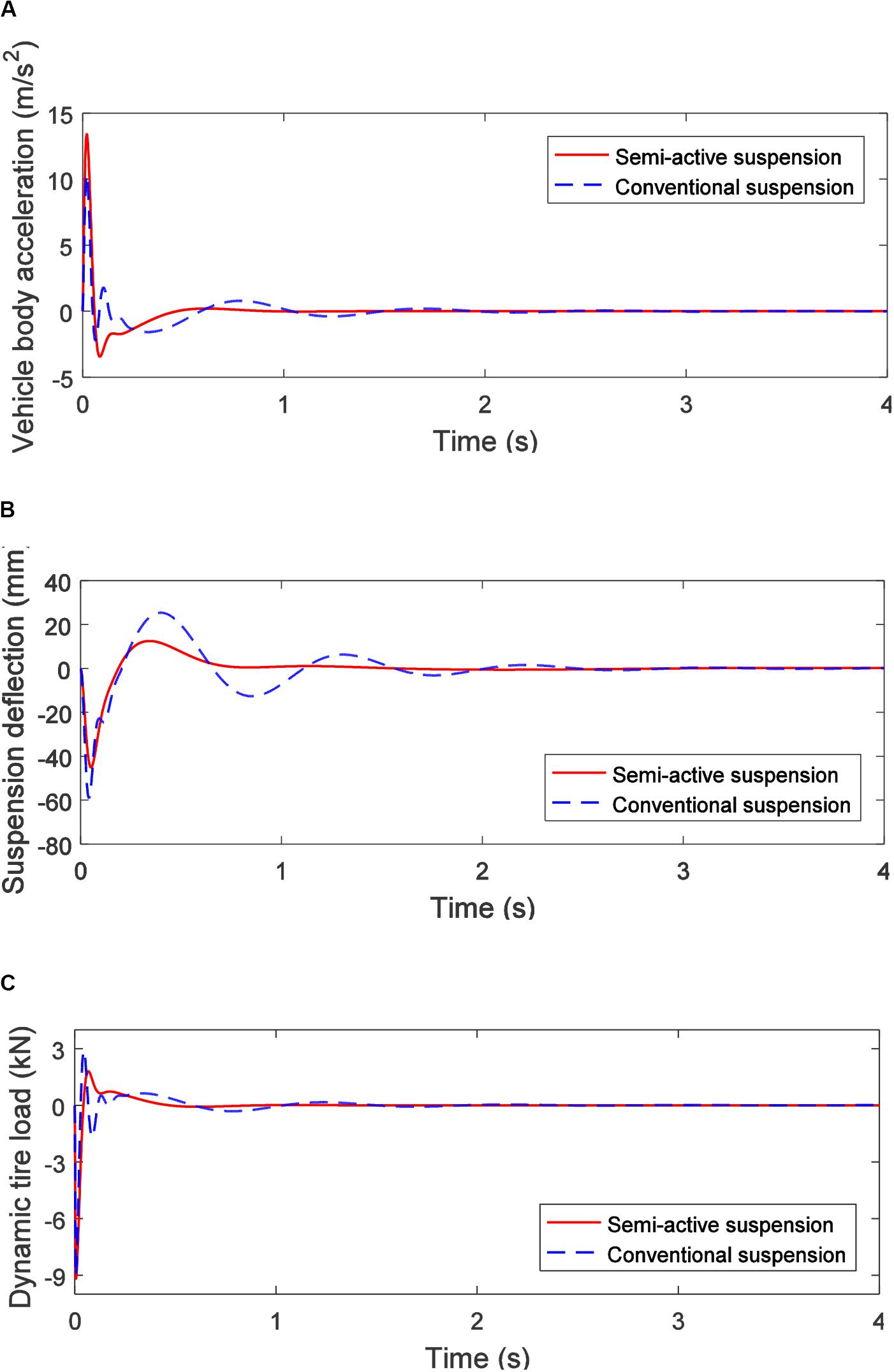
Figure 15. Unit impulse response of the 1/4 vehicle suspension: (A) vehicle body acceleration, (B) suspension deflection, and (C) dynamic tire load.
As shown in Figure 15B, the suspension deflection performance of the semi-active suspension is significantly better than that of the conventional suspension, and the amplitude and the attenuation speed are both significantly improved compared to the conventional suspension. As shown in Figure 15C, the dynamic tire load of the semi-active suspension is almost equivalent to that of the conventional suspension and has a slight advantage in attenuation speed.
Conclusion
In this paper, an adjustable inerter based on MR fluid—MR inerter, and its adjustment principle of inertance were proposed. Based on the design concept of “functional integration”, the MR inerter, MR damper, and spiral spring were highly integrated to realize a new IISD with both tunable inertance and damping. The MR inerter is mainly composed of an MR clutch, a ball screw, a flywheel, excitation coils, and MR fluid. The mathematical model of the IISD was established, and the adjustment principle of the inertance was verified by numerical simulation. The mechanical output characteristics of the IISD under different inertance and damping coefficients were analyzed. Finally, a 1/4-vehicle suspension model with the IISD was established by using MATLAB/SimMechanics, and a virtual comfort-oriented experiment was carried out. The concluding remarks are summarized as follows:
1. The adjustment of inertance based on the MR fluid, which has the advantages of rapid response, low energy consumption, and wide adjustment range, i.e., the inertance can be tuned from 86 to 927 kg.
2. The functional integration concept makes the IISD realize a combination of both tunable inertance and damping coefficient with a very compact structure, which is beneficial to the application of specific limited installation cases, such as vehicle suspensions.
3. The proposed MR inerter transfers the problem of inertance adjustment to rotate velocity control by using MR clutch, which simplified the adjustment method of inertance.
4. Increasing the gap width between the MR clutch casings can effectively improve the adjustment range of the inertance.
5. The vehicle body acceleration of the semi-active suspension is reduced by 23.0% compared with the conventional suspension, and the suspension deflection and the dynamic tire load are reduced by 0.8 and 1.1%, respectively.
Data Availability Statement
The datasets generated for this study are available on request to the corresponding author.
Author Contributions
W-MZ carried out the modeling, computation and simulation work, and drafted and revised the manuscript. A-DZ investigated the technical background, and helped draft and revise the manuscript. X-XB conceived the conception, designed and coordinated the study, and revised the manuscript. NW did modeling checking, and helped draft and revise the manuscript. NZ helped revise the manuscript. All authors contributed to the article and approved the submitted version.
Funding
The authors wish to acknowledge the Key Research and Development Projects of Anhui Province (Grant No. 1704E1002211) for the support of this research.
Conflict of Interest
The authors declare that the research was conducted in the absence of any commercial or financial relationships that could be construed as a potential conflict of interest.
References
Bai, X. X., Jiang, P., and Qian, L. J. (2017). An integrated semi-active seat suspension for both longitudinal and vertical vibration isolation. J. Intellig. Mater. Syst. Struct. 28, 1036–1049. doi: 10.1177/1045389x16666179
Bai, X. X., Wereley, N. M., and Chio, Y. T. (2016). Magnetorheological energy absorber with dual concentric annular valves. J. Intellig. Mater. Syst. Struct. 27, 944–958. doi: 10.1177/1045389x15577659
Bai, X. X., Zhong, W. M., Zou, Q., Zhu, A. D., and Sun, J. (2018). Principle, design and validation of a power-generated magnetorheological energy absorber with velocity self-sensing capability. Smart Mater. Struct. 27:075041. doi: 10.1088/1361-665x/aac7ef
Brzeski, P., Pavlovskaia, E., Kapitaniak, T., and Perlikowski, P. (2015). The application of inerter in tuned mass absorber. Int. J. Non Linear Mech. 70, 20–29. doi: 10.1016/j.ijnonlinmec.2014.10.013
Chen, M. Z., Papageorgiou, C., Scheibe, F., Wang, F. C., and Smith, M. C. (2009). The missing mechanical circuit element. IEEE Circ. Syst. Magaz. 9, 10–26. doi: 10.1109/mcas.2008.931738
Giaralis, A., and Petrini, F. (2017). Wind-induced vibration mitigation in tall buildings using the tuned mass-damper-inerter. J. Struct. Eng. 143:04017127. doi: 10.1061/(asce)st.1943-541x.0001863
Hu, Y., Chen, M. Z., Xu, S., and Liu, Y. (2016). Semiactive inerter and its application in adaptive tuned vibration absorbers. IEEE Trans. Control Syst. Technol. 25, 294–300. doi: 10.1109/tcst.2016.2552460
Imaduddin, F., Mazlan, S. A., and Zamzuri, H. (2013). A design and modelling review of rotary magnetorheological damper. Mater. Des. 51, 575–591. doi: 10.1016/j.matdes.2013.04.042
Kaluvan, S., Thirumavalavan, V., Kim, S., and Choi, S. B. (2015). A novel magnetorheological actuator for micro-motion control: identification of actuating characteristics. Smart Mater. Struct. 24:105006. doi: 10.1088/0964-1726/24/10/105006
Matamoros-Sanchez, A. Z., and Goodall, R. M. (2015). Novel mechatronic solutions incorporating inerters for railway vehicle vertical secondary suspensions. Vehicle Syst. Dyn. 53, 113–136. doi: 10.1080/00423114.2014.983529
Papageorgiou, C., Houghton, N. E., and Smith, M. C. (2009). Experimental testing and analysis of inerter devices. J. Dyn. Syst. Meas. Control 131:011001.
Papageorgiou, C., and Smith, M. C. (2006). Positive real synthesis using matrix inequalities for mechanical networks: application to vehicle suspension. IEEE Trans. Control Syst. Technol. 14, 423–435. doi: 10.1109/tcst.2005.863663
Sapiñski, B., Rosół, M., and Wêgrzynowski, M. (2016). Investigation of an energy harvesting MR damper in a vibration control system. Smart Mater. Struct. 25:125017. doi: 10.1088/0964-1726/25/12/125017
Shiao, Y., Ngoc, N. A., and Lai, C. H. (2016). Optimal design of a new multipole bilayer magnetorheological brake. Smart Mater. Struct. 25:115015. doi: 10.1088/0964-1726/25/11/115015
Smith, M. C. (2002). Synthesis of mechanical networks: the inerter. IEEE Trans. Autom. Control 47, 1648–1662. doi: 10.1109/tac.2002.803532
Smith, M. C., and Wang, F. C. (2004). Performance benefits in passive vehicle suspensions employing inerters. Vehicle Syst. Dyn. 42, 235–257. doi: 10.1080/00423110412331289871
Tipuric, M., Deastra, P., Wagg, D., and Sims, N. (2018). “Semi-active inerters using magnetorheological fluid: a feasibility study,” in Proceedings of the Active and Passive Smart Structures and Integrated Systems XII. International Society for Optics and Photonics, Denver, CO.
Wang, F. C., and Chan, H. A. (2008). “Mechatronic suspension design and its applications to vehicle suspension control,” in Proceedings of the 2008 47th IEEE Conference on Decision and Control, (Piscataway, NJ: IEEE), 3769–3774.
Zhong, W. M., Bai, X. X., Tang, C., and Zhu, A. D. (2019). Principle study of a semi-active inerter featuring magnetorheological effect. Front. Mater. 6:17. doi: 10.3389/fmats.2019.00017
Appendix
According to the structural parameters of the integrated inerter-spring-damper (IISD) listed in Table A1, a 1/4 vehicle suspension model with the IISD is established in MATLAB/SimMechanics, as shown in Figure A1, and the suspension parameters are listed in Table A2.
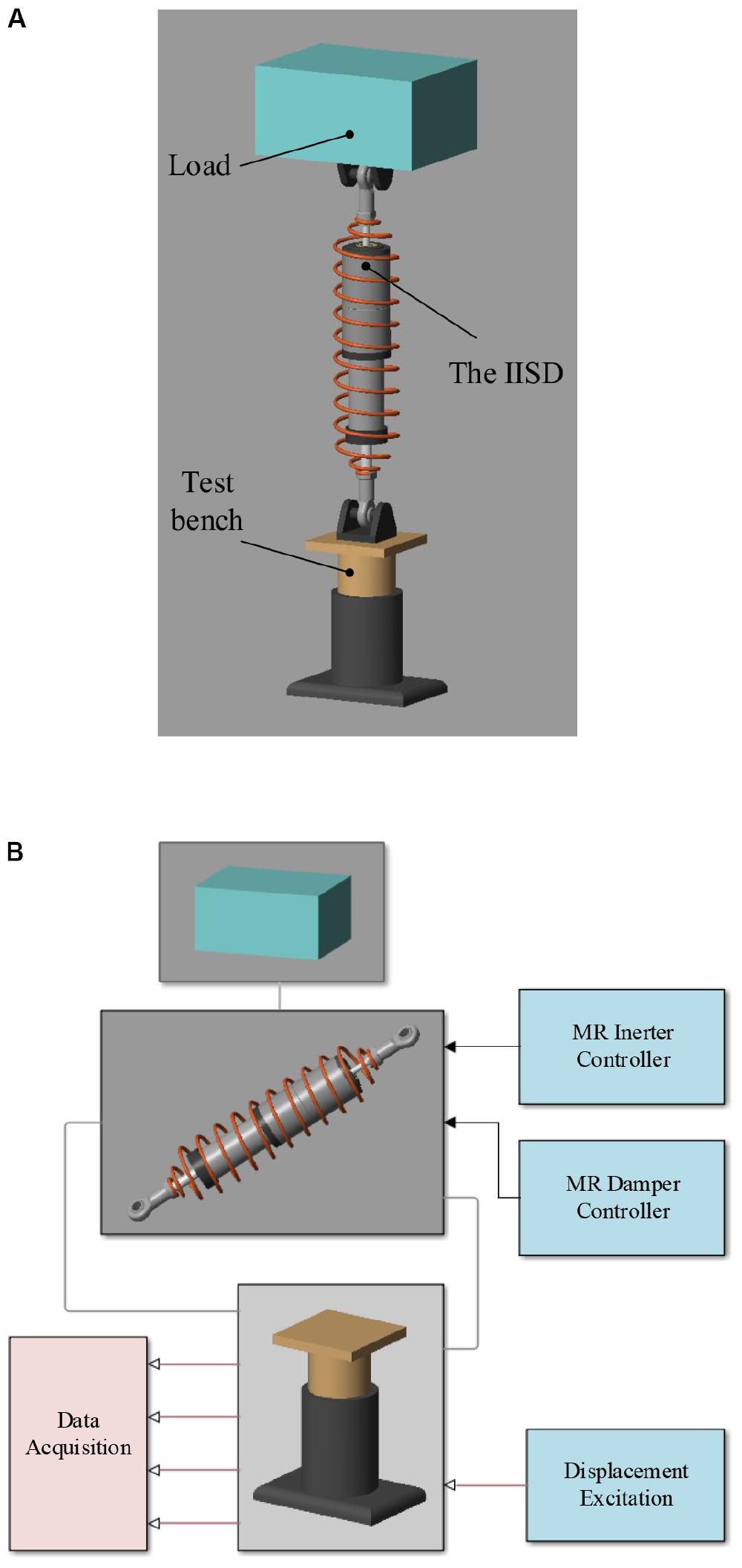
Figure A1. MATLAB/SimMechanics model of the 1/4 vehicle suspension: (A) three-dimensional model and (B) Simulink model.
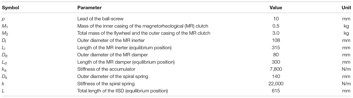
Table A1. Structural parameters of the integrated inerter-spring-damper.
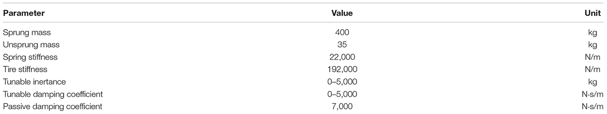
Table A2. Simulation parameters of 1/4 vehicle suspension.
Keywords: tunable inertance, magnetorheological fluid, MR inerter, ISD suspension, functional integration
Citation: Zhong W-M, Zhu A-D, Bai X-XF, Wereley NM and Zhang N (2020) Integrated Shock Absorber With Both Tunable Inertance and Damping. Front. Mater. 7:204. doi: 10.3389/fmats.2020.00204
Received: 08 November 2019; Accepted: 03 June 2020;
Published: 09 July 2020.
Edited by:
Ilkwon Oh, Korea Advanced Institute of Science and Technology, South KoreaReviewed by:
Jung Woo Sohn, Kumoh National Institute of Technology, South KoreaSeung-Bok Choi, Inha University, South Korea
Copyright © 2020 Zhong, Zhu, Bai, Wereley and Zhang. This is an open-access article distributed under the terms of the Creative Commons Attribution License (CC BY). The use, distribution or reproduction in other forums is permitted, provided the original author(s) and the copyright owner(s) are credited and that the original publication in this journal is cited, in accordance with accepted academic practice. No use, distribution or reproduction is permitted which does not comply with these terms.
*Correspondence: Xian-Xu Frank Bai, YmFpQGhmdXQuZWR1LmNu; Norman M. Wereley, d2VyZWxleUB1bWQuZWR1