 Leyang Lv
 Xin Hong1
- 1Guangdong Province Key Laboratory of Durability for Marine Civil Engineering, School of Civil Engineering, Shenzhen University, Shenzhen, China
- 2Guangdong Province Academy of Building Research Group Co., Ltd., Guangzhou, China
- 3China Construction Eighth Engineering Division Co., Ltd., Shanghai, China
In this work, quick hardening and high early strength engineered cementitious composites (ECC) were developed by using calcium sulfoaluminate (CSA) cement as the matrix material. The optimal mix design of CSA-ECC was studied with emphasis on the fluidity and mechanical properties. It was found that CSA cement incorporated with 2% polycarboxylate-based superplasticizer (PSP), 1% ultra-high-molecular weight polyethylene (UHMWPE) fiber, and with cement to sand ratio of 0.5 shows the best performance in terms of fluidity, flexural strength, and compressive strength. The fracture energy, tensile strength, and strain capacity of CSA cement was significantly improved by proper mixing of UHMWPE fiber. After that, the performance of CSA-ECC in rapid repairing of concrete members was characterized. The experimental results suggest that the CSA-ECC has good bonding strength to the concrete matrix. Compared with plain concrete members, both flexural and compressive strength of concrete members were significantly reinforced after 1, 3, and 28 days when CEA-ECC was applied as rapid repairing coating.
Introduction
Concrete is one of the world’s most widely used single artificial material (Moradi-Marani et al., 2010). However, deterioration often occurs in concrete due to aging factors such as mechanical load (e.g., overload, fatigue) (Leung et al., 2007), environmental impact (e.g., freezing and thawing, chloride invasion) (Liu et al., 2017; Van Belleghem et al., 2018), and volumetric variation (e.g., creep, thermal contraction) (Sirtoli et al., 2019; Yang et al., 2019). Although better mix design could reduce the speed of deterioration and the risk of structural failure, a good maintenance and necessary repairment are still highly required. Traditional concrete repair methods are expected to prolong the service life of reinforced concrete structures, while the result is unfortunately not always optimistic. According to the data provided by ConRepNet research (Jacobs, 2010), 20% of these repairs fail within 5 years. This number rose to 55% within 10 years and 90% within 25 years of service. Especially in developing countries, for example, China, after 40 years of massive construction, concrete structures such as airstrips, bridges, and tunnels are either approaching designed service life or servicing exceeded its original design load. There is an urgent need to develop proper repairing and reinforcing materials which can not only prevent the concrete structure from being influenced by the aging factors but also enhance their mechanical performance to meet the new application requirement.
Engineered cementitious composite (ECC) is a special type of fiber-reinforced cementitious composite. For this type of material, a significant higher tensile ductility and fracture energy can be realized by reasonably adding no more than 2% of fiber into the cementitious matrix (Li et al., 2001; Zhou et al., 2019; Xiong et al., 2020). Once there is failure, the imposed load on ECC can be distributed by cracking at multiple locations with narrow crack width, featuring a strain-hardening behavior (Kanda and Li, 2006; Zhou et al., 2019). In previous study, it has been demonstrated that ECC can serve as an effective repairing material for concrete restoration (Lim and Li, 1997; Li et al., 2000; Cao et al., 2011; Huang et al., 2013). Thanks to its good ductility and high fracture energy, ECC can effectively defuse the formation and stop the propagation of cracks in the concrete matrix. Moreover, the typical crack width of ECC at the strain hardening regime is about 50 μm, which is apparently lower than the value of public recognized hazardous crack width (Sahmaran and Li, 2009; Liu et al., 2016). When ECC was applied as repairing materials on the concrete structures, air and aggressive agents cannot easily transport through the micro-crack in ECC. The durability of the repaired concrete structure can therefore be greatly improved.
At present, most of the research on ECC is based on Ordinary Portland Cement (OPC), which has relatively long hardening time and low strength develop rate. However, in practice, many repairing works have a strict demand on the working duration, which puts higher requirements on the early strength of repairing materials. For example, the repair job of a main road has to be completed within 5 to 6 h in the night so that the road can be reopened to traffic next morning (Parker and Lee Shoemaker, 1991). Military infrastructure must be repaired as quickly as possible to renew its usage function. The window period for repairing an airport runway is even shorter. In order to minimize the flight delay, the repairing work has to be finished without closing the airport for runway maintenance (Luo et al., 2013).
Calcium sulfoaluminate (CSA) cement mainly based on the mineral substance ye’elimite (4CaO⋅3Al2O3⋅SO3) has comparable early and late strength, less volume shrinkage, and low environmental impact compared to OPC (Bullerjahn et al., 2019b). The ye’elimite reacts rapidly with water followed by the formation of initial ettringite and aluminum hydroxide (Winnefeld and Barlag, 2010; Bullerjahn et al., 2019a). The very short hardening time of CSA cement, to a large extent, could promote the repairing efficiency and reduce the public interruption (Guan et al., 2017). In addition, CSA cement has good frost resistance, chemical erosion resistance, and anti-permeability, and it is widely used in road and building repairment, structural reinforcement, and wastes immobilization (Liao et al., 2011; Jen et al., 2017; Winnefeld et al., 2018). Li and Li (2011) took the lead in developing high early strength ECCs by incorporation of PVA fiber into CSA cement. The results suggest that the prepared high early strength ECC materials are capable of providing a compressive strength of 21 MPa within 4 h and tensile strain capacity of 2%. Recently, Wang et al. (2019) developed sulfoaluminate cement based ultra-high performance concrete (ES-UHPC) which uses steel fiber as reinforcement. The ES-UHPC exhibited significant tensile strain-hardening behavior under tensile load. In addition, the reinforcing performance of different types of fibers on the engineering properties of CSA cement-based concrete was evaluated (Afroughsabet et al., 2019). However, to the best of the authors’ knowledge, most of those works are concentrated on the preparation and characterization of the materials themselves. There is no report that can be found in the literature focus on the performance of CSA based ECC (CSA-ECC) in concrete repairment.
Based on the discussion above, the motivation of this work was to evaluate the potential of using CSA-ECC as a coating material for concrete element reinforcing and repairing. To this end, ultra-high-molecular weight polyethylene (UHMWPE) fibers was used to produce CSA-ECC materials. Orthogonal method was applied to screen out the optimal mix design of CSA-ECC, with emphasis on both aspects of mechanical strength and tensile strain capacity. The micro-structure of UHMWPE fibers in CSA cement was observed with environmental scanning electron microscope (ESEM). Finally, with the comparison of plain concrete, the repairing performance of the prepared CSA-ECC at different age was characterized on concrete beam and concrete column, respectively. The scientific findings obtained in this study are considered to contribute to further study of prolonging the service life of existing concrete structure with satisfactory materials.
Materials and Methods
Materials
High-belite CSA cement (HB-CSA) was provided by Polar Bear building materials Co., Ltd., (Beijing, China). The technical index is shown in Table 1 and the chemical analysis is given in Table 2. The main constituents of HB-CSA as derived from X-ray diffraction and XRF analyses were ye’ elimite (54%), belite (19%), and anhydrite (21%).
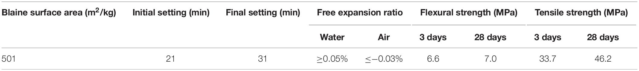
Table 1. Technical index of the used HB-CSA cement.

Table 2. Chemical composition of the used HB-CSA cements (L.O.I. = loss on ignition).
Ultra-high-Molecular Weight Polyethylene (UHMWPE) fibers were purchased from the Royal DSM NV (The Netherlands). The geometry and mechanical properties of the UHMWPE fibers are shown in Table 3. Fine silica sand with particle size in the range of 150–180 μm was applied as natural fine aggregate. Polycarboxylate-based superplasticizer (PSP, water-reducing ratio 41%), which was used as the water-reducer of the cementitious binder, was obtained from Guangdong Fute new materials technology Co., Ltd. (Foshan, China). Tap water was used as batch water for sample preparation.

Table 3. The geometry and mechanical properties of the used UHMWPE fibers.
Mix Design
The mixture proportions were designed by considering the potential influence factors including the cement to sand ratio, the proportion of additives, and the fiber content on the workability and mechanical properties of the CSA-ECC. Three levels of value were assigned to each influence factor. The water to cement ratio was set constantly as 0.28. The specimen ID and its corresponding mixture proportion are summarized in Table 4.
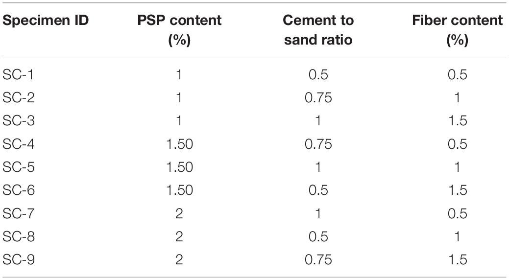
Table 4. Summary of the mix design proportion.
Mixing Procedure and Sample Preparation
A good dispersion of the UHMWPE fiber in the cementitious matrix is very important to the final performance of the composite materials. In this study, the mixtures were prepared by the following three steps. In the first step, dry CSA was mixed with fine silica sand for 1 min. Secondly, under mechanical stirring, manually dispersed UHMWPE fiber was added slowly to the mixture and rapid stirred for 1 min. Finally, the pre-prepared PSP dissolved water solution was added in the mixture and stirred for another 2 min. After the mixing was completed, the prepared mixture was poured into the mold (the shape of mold depends on the required test) and vibrated for about 30 s to remove the air bubbles. All the specimens were demolded after 24 h of sealed curing, and then cured in lab conditions (65 ± 5% relative humidity at 23 ± 2°C) until test.
Fluidity
The fluidity of the prepared CSA-ECC was evaluated by testing the flow diameter immediately after the mixing procedure according to the testing standard EN 459-2:2010.
Mechanical Properties
Flexural and Compressive Strength
The flexural strength and compressive strength of the prepared CSA-ECC material after 1, 3, and 28 days of curing was evaluated on 40 mm × 40 mm × 160 mm specimens according to the testing standard EN 196-1. The flexural strength of specimens was tested under three-point loading with the span between supports being 100 mm. The loading rate was 50 ± 10 N/s. The average of results obtained from three prismatic specimens was reported as flexural strength. The two halves of the 40 mm × 40 mm × 160 mm retained after the flexural strength test were used for compressive strength. The loading rate was 2400 ± 200 N/s. The loading area was 40 mm × 40 mm. The average of results obtained from six broken pieces was reported as compressive strength. In cases where one result varies by more than 10% from the mean, the result will be discarded and the arithmetic mean of the remaining results will be considered as the final result.
Fracture Energy
The fracture energy of CSA-ECC was measured on single edge notched specimens according to the test scheme RILEM 1985–FMCFMC (Recommendation, 1985). The tensile test was loaded (MTS Criterion C64.305, United States) with a loading rate of 0.2 mm/min. Figure 1 shows the sketch map of the applied specimens. P stands for the real-time loading, L represents the length of specimen, t is the width of the specimen, b is the span between supports, a is the depth of the notch, and h is the height of fracture surface.
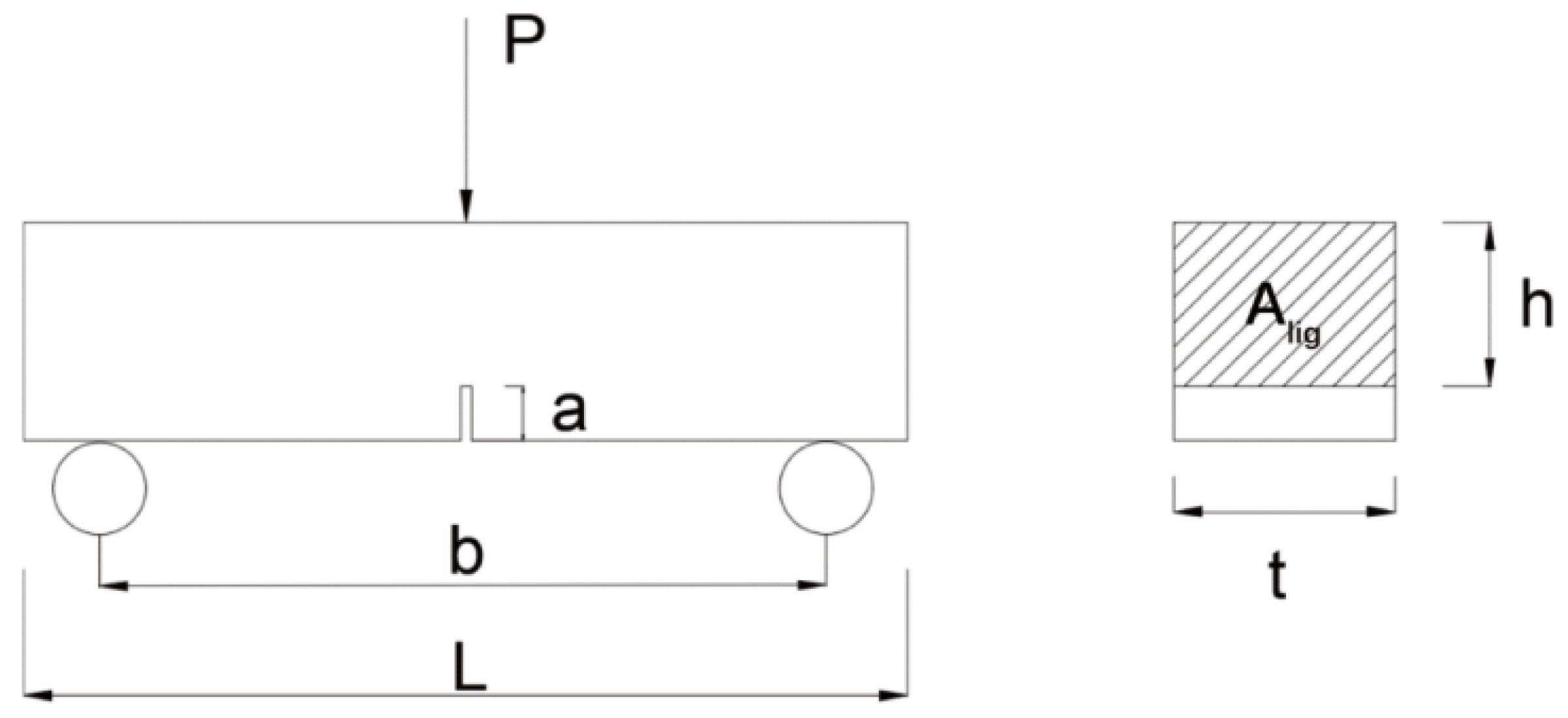
Figure 1. Sketch map of the specimens used in the fracture energy measurement, where a = 10 mm, b = 100 mm, L = 1600 mm, and h = 30 mm.
Based on the load-displacement curve, the fracture energy of the CSA-ECC material can be calculated from the following equation:
where W0 is the work of the external load which can be calculated by the area under the load-deflection curve, m is the weight of the beams, g represents acceleration due to gravity equal to 9.81 m/s2, δ0 is the deflection at the final failure of the beam, and Alig is area of the ligaments of notched beams.
Tensile Strength
The tensile strength of the prepared CSA-ECC materials was performed on dog bone-shaped specimens according to the specification of the Japan Society of Civil Engineers (JSCE) recommendations (JSCE, 2008). To obtain the tensile stress-strain curves, the tensile test was loaded (MTS Criterion C64.305, United States) with a loading rate of 0.5 mm/min. Two linear variable displacement transducers (LVDTs) were installed at both sides of the dog bone-shaped specimen with a gage length of 80 mm to determine the full-range stress-strain relationship. The tensile test was carried on specimens after 1, 3, and 28 days of curing in standard lab condition 60 ± 10% relative humidity at 23 ± 2°C. In addition, the fracture distribution is observed using Full-Field 3D Strain Measurement System (VIC-3D, Correlated Solution, United States). The non-contact measurement method can quantitatively observe the displacement and strain field of the test object. Before the test, the surface of the test piece is sprayed with black and white paint to form a random speckle image. During the tensile and bending tests, a digital camera was placed in front of the test machine to capture digital image information at intervals of 20 s. After the test, the image correlation analysis software VIC 3D was used for post-processing to obtain the displacement and strain fields. Figure 2 shows the images of (a) the non-contact full-field 3D strain measurement system and (b) specimen prepared for VIC-3D test.
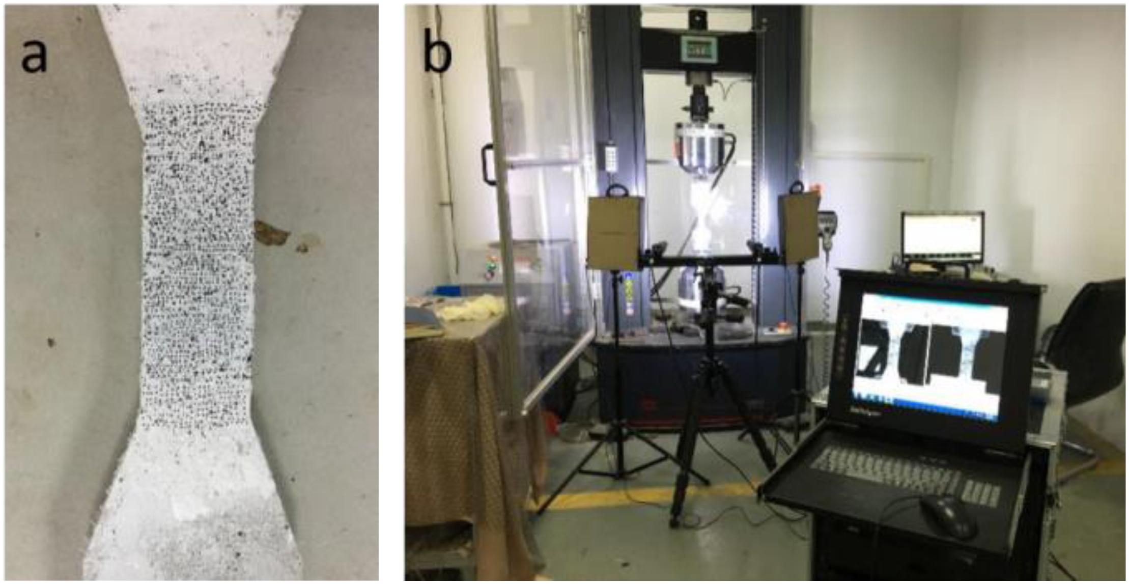
Figure 2. Images of (a) specimen prepared for VIC-3D test and (b) the non-contact full-field 3D strain measurement system.
Micro-Structure of CSA-ECC
To have an in-depth understanding of the microstructure of CSA-ECC, the fractured surface of CSA-ECC after 28 days of curing was also studied. The surface of fiber and the state of fiber in CSA cement was characterized by environmental scanning electron microscope (Quanta FEG 250, FEI, United States) in low vacuum.
Performance Characterization
Bonding Strength Between CSA-ECC and Concrete Matrix
The bonding strength between SAC-ECC and concrete matrix was evaluated through three-point bending test. Before the test, 40 × 40 × 160 mm mortar prism was casted with water to cement ratio of 0.5 and cement to sand ratio of 1/3. After curing in a standard curing room for 28 days, the specimens were cut into two halves and the cutting surface was polished with sand paper. By placing one half into the 40 × 40 × 160 mm mold and filling the rest of the mold space with CSA-ECC, two-halves specimens were made. The specimens were demolded after 24 h of curing and then transferred into a curing room for further hydration. Figure 3 shows the final product of the two-halves specimens. The flexural strength of the specimen was evaluated on specimens after 1, 3, and 28 days of standard curing. The flexural strength of the two-halves specimens was considered as a reflection of the bonding strength between CSA-ECC and concrete matrix.
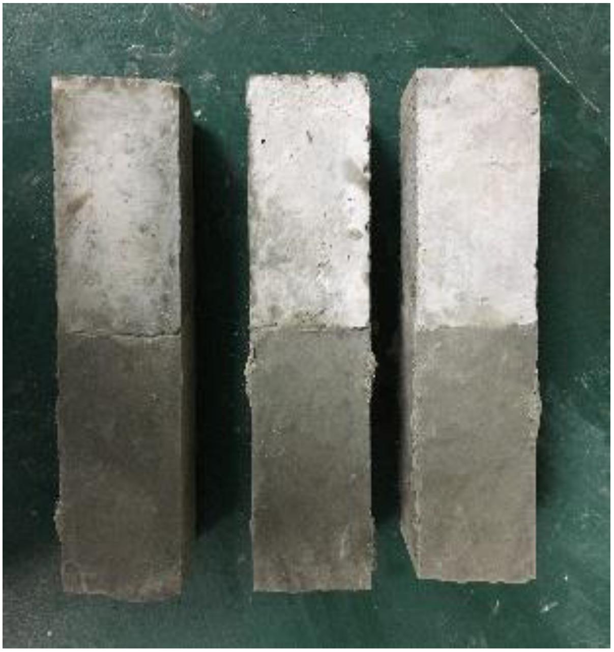
Figure 3. Final product of the two-halves (CSA-ECC/mortar) specimens.
Flexural Strength Reinforcement
The performance of the CSA-ECC in flexural strength repairment was evaluated on a 400 mm × 100 mm × 100 mm concrete beam. Before applying the CSA-ECC to the concrete beam, about 2 mm of the top layer of the concrete beam was removed by air chipping hammer (SHANLI machinery technology, China) to increase the bonding strength between the concrete matrix and the CSA-ECC material. Steel brush was used to remove the powder and sand on the surface. Then a layer of about 5 mm CSA-ECC slurry was evenly coated on the beam. Plastic film was applied to seal the top surface of the repaired samples. The sealed concrete beam was stored in lab condition until the age of test.
The flexural strength of the repaired concrete beam was characterized in accordance with the Chinese standard GB/T 50081-2002. The grade of the concrete beam used in this study is C40. The 28 days flexural strength of the plain concrete beam is 5.9 MPa. The flexural strength of plain concrete at 28 days and CSA-ECC repaired concrete beam after 1, 3, and 28 days of curing was evaluated based on an average of three replicates. The flexural strength of the repaired concrete beam was calculated according to Eq. 1:
where ff (MPa) is the flexural strength of repaired beam, F is the load applied on the beam, L stands for the span of two supports, b and h represent the width and height of the cross section. Figure 4 shows the schematic of the flexural strength test for single side repaired concrete.
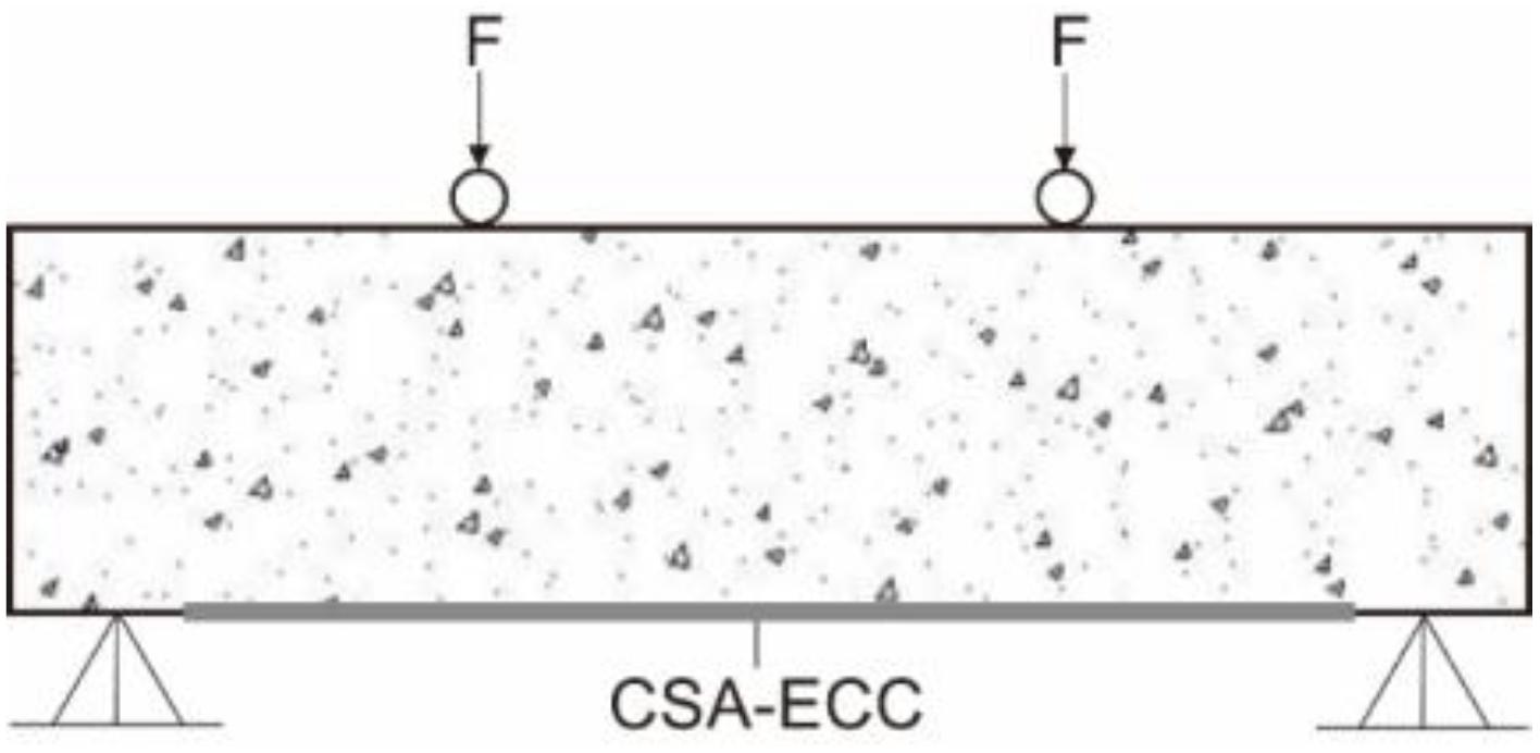
Figure 4. Testing schematics for concrete beam reinforcement.
Compressive Strength Reinforcement
The axial compression is another fundamental test for gaining an improved understanding of the behavior of the cementitious materials (Tang et al., 2020). The performance of CSA-ECC in compressive strength reinforcement was characterized on concrete column (300 mm long and with a diameter of 150 mm). Similar to the flexural strength test, 5 mm of the vertical surface of the column was first removed by air chipping hammer. Then the vertical surface of the column was coated with a 5 mm thick layer of CSA-ECC reinforcing slurry to make the final repaired column with the same size as the plain concrete column. A special cylindrical mold with a diameter of 150 mm was made to secure that the thickness of coating is 5 mm. The flexural strength of plain concrete and repaired concrete beam at 1, 3, and 28 days was measured based on an average of three replicates. The compressive strength was calculated via Eq. 2:
where fcc(MPa)is the compressive strength of specimen, F is failure load, and d stands for the diameter of the column. Figure 5 shows the schematic of the repaired concrete column.
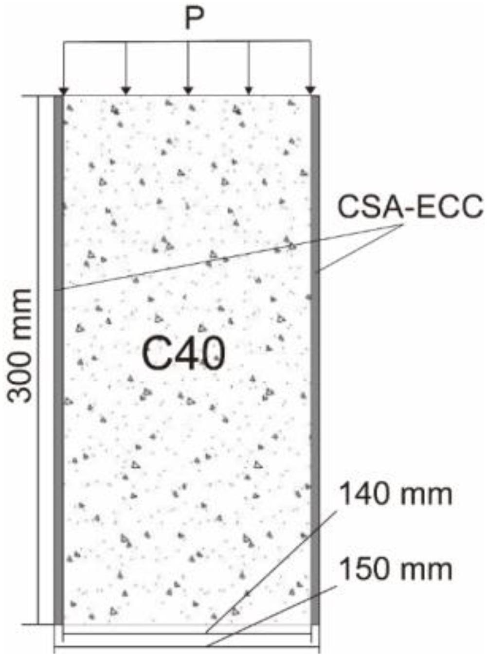
Figure 5. Schematic of the repaired concrete column under compressive strength test.
Results and Discussion
Optimization of Mix Design
Fluidity
Table 5 shows the results of the fluidity test. It was found that the mix design of SC-7 and SC-8 possesses the highest fluidity. A flow diameter of 160 mm was measured. On the contrary, SC-3 sample has the lowest fluidity among all nine samples while 130 mm of flow diameter was characterized. The reason for the relatively low flow diameter of SC-3 can be attributed to the higher ratio of fiber content and sand content in the mixture. Too much fiber content leads the fiber in the mixture to become a tuck net, preventing the further sprawling of the flow. In addition, larger amounts of sand means the wetting of sand requires higher volume of water. The water to cement ratio is a constant value, and mixture with higher ratio of cement to sand ratio results in less fluidity. Nevertheless, the flow diameter of all nine samples falls in the range between 130 and 160 mm. This means that the fluidity of the mix designs is satisfied with the basic requirement of cementitious materials.

Table 5. Results of fluidity test.
Flexural Strength
The flexural strength of the CSA-ECC specimens at 1, 3, and 28 days of curing are shown in Figure 6. It is obvious that the SC-8 sample has the highest flexural strength among these nine samples, followed by SC-6, SC-4, and SC-1. The flexural strength of SC-8 after 1, 3, and 28 days of curing are 14.6, 15.2, and 19.4 MPa, respectively, which is significantly higher than that of the plain CSA without fiber reinforcement (7 MPa). In addition, it was found that the flexural strength increased significantly at the first day of hydration. Up to 60% of the 28 d flexural strength can be achieved. This result suggests that the UHMWPE fiber can be used to enhance the flexural strength of the HB-CSA cement. The prepared CSA-ECC possesses a rapid hardening and high early strength property.
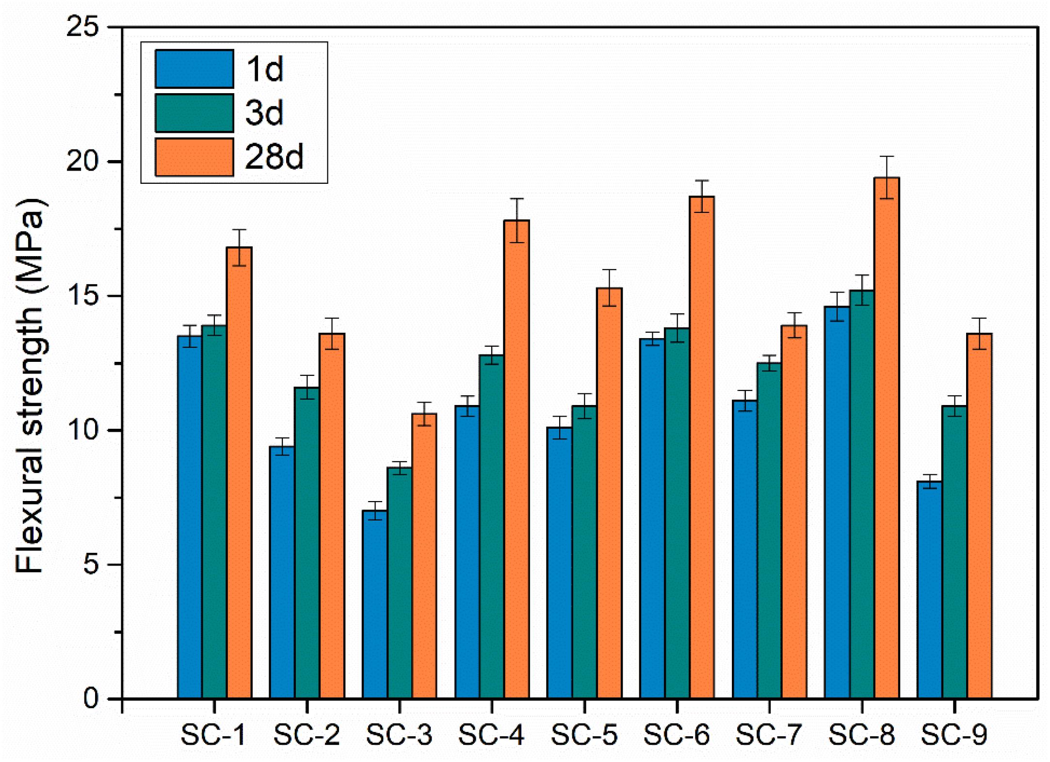
Figure 6. Flexural strength of CSA-ECC specimens after curing for 1, 3, and 28 days.
Compressive Strength
The compressive strength of CSA-ECC specimens cured for 1, 3, and 28 days was measured, and the result is shown in Figure 7. It was found that the compressive strength increased significantly at the first 24 h of hydration. A minimal 30 MPa of compressive strength can been achieved for all nine mixtures and topped out at 44 MPa for the SC-5 specimen. Despite that the compressive strength of all nine mixtures have exceeded 40 MPa, with the increase of curing time, the SC-8 specimen shows the best performance. On the SC-8 sample, 60.2 MPa of compressive strength was characterized, and this number increased further to 71.3 MPa after 28 days of curing. Moreover, it was noticed that the difference in compressive strength between these nine mixtures is less significant comparing with flexural strength. This phenomenon implies that the difference in cement to sand ratio, SP and fiber content have less effect on the final compressive strength of the CSA-ECC material.
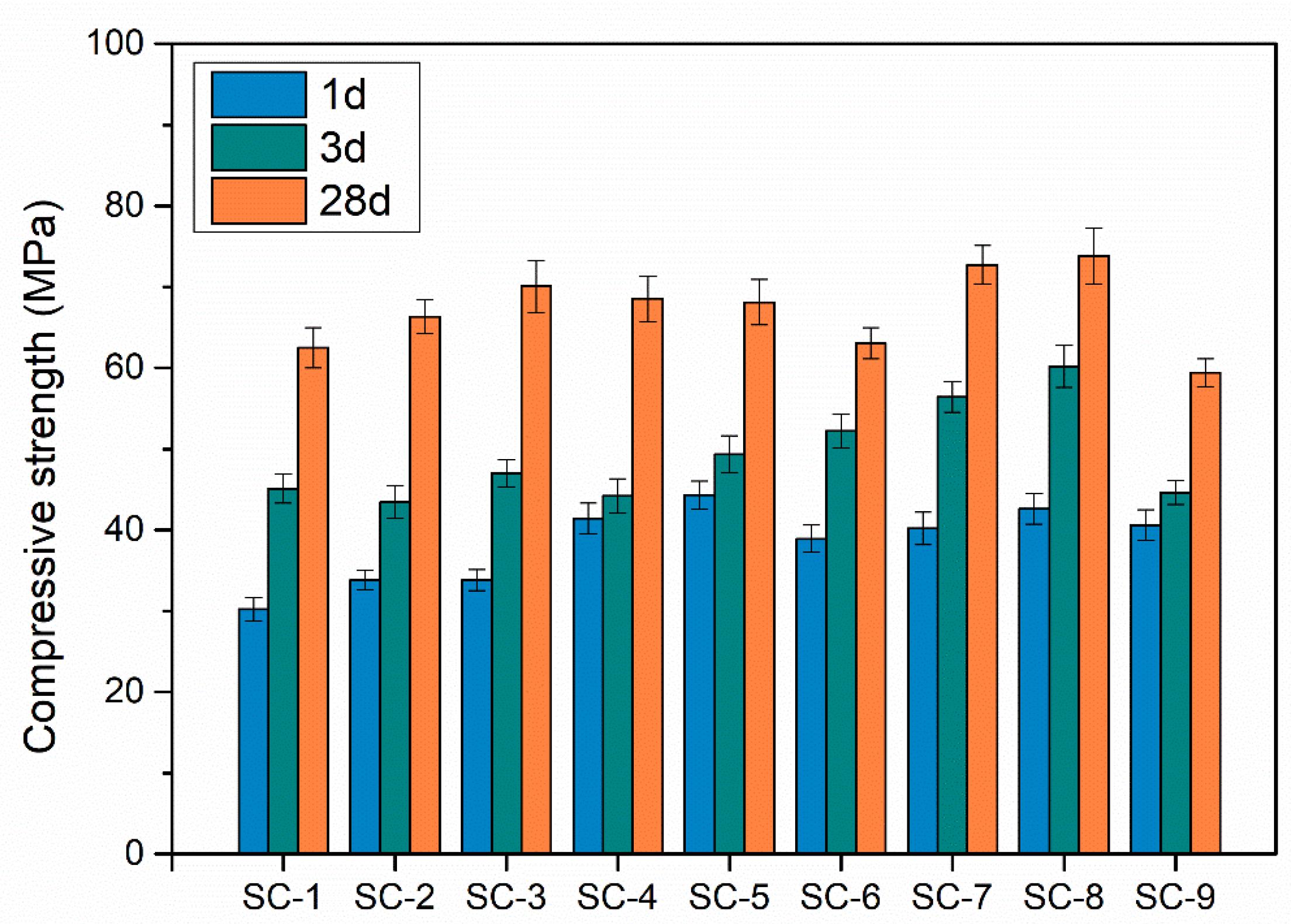
Figure 7. Compressive strength of CSA-ECC specimens after curing for 1, 3, and 28 days.
After-Failure Morphology Analysis
Figure 8 shows the after-failure morphology of the 40 mm × 40 mm × 160 mm specimens under flexural strength test (a) and compressive strength test (b). Similar to the behavior of OPC based ECC, a multi-crack phenomenon can also be observed from the prepared CSA-ECC material. The occurrence of this phenomenon can be attributed to the presence of UHMWPE fiber and the good mix design. In the flexural strength test, once the uniaxial loading reached the initial cracking strength of the matrix, the first crack appears. Due to the good bonding performance between the fiber and CSA matrix, the loading could be passed from the fractured matrix to the adjacent uncracked area through the fiber. Once the crack number and width reached the saturation, the process of multi-crack fracturing will be terminated by the formation of main crack. As for the compressive strength test, the after-test specimen was found not completely broken up with multi-cracking characteristic. The specimen shown an obvious plastic deformation.
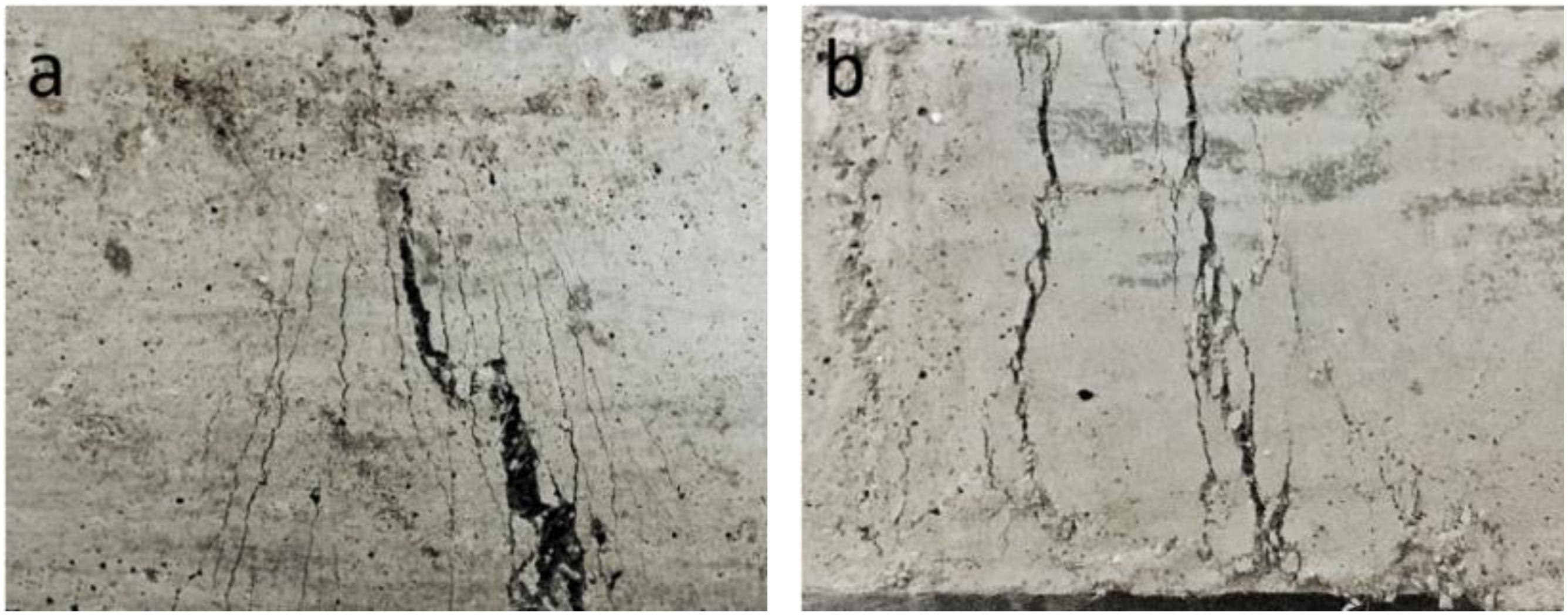
Figure 8. The multiple-cracking behavior of HSHLW-ECCs under (a) flexural strength test and (b) compressive strength test.
Fracture Energy
Figure 9 shows typical load-deflection curves of the CSA-ECC sample (hereinafter with mix design SC-8) after 1, 3, and 28 days of curing, and the results were compared with the control specimens (plain HB-CSA cement) at 28 day. The development pattern of the load-displacement curve of all CSA-ECC specimens was found apparently different from the control specimen. It was found that the failure load of CSA-ECC repaired concrete column increased with the increase of repairing age. The fracture process of CSA-ECC specimens consumed more energy than the control specimens, which can be reflected from the significantly wider area under the load-deflection curve. In addition, the peak load was found increased as the curing age extended.
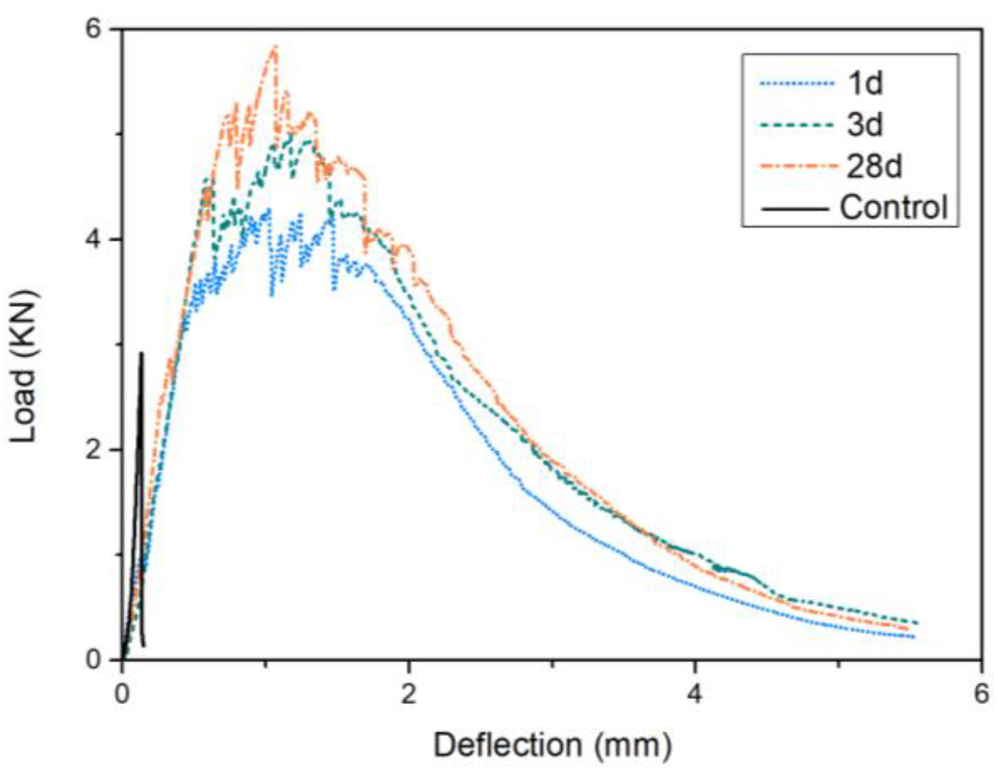
Figure 9. Typical load-deflection curves of the control specimens at 28 d and CSA-ECC specimens after 1, 3, and 28 days of curing.
Fracture energy was used to express the energy required to create the new fracture surface of a material or composite. In this study, the fracture energy of the CSA-ECC and the control specimens (plain HB-CSA cement) were calculated with the Eqs (1) and (2) based on the results of the load-deflection curves. As can be seen from Figure 10, the fracture energy of the control specimen without UHMWPE fiber is 114, 237, and 281 J/m2, respectively, after 1, 3, and 28 days of curing. By adding 0.75% UHMWPE fibers, the fracture energy of CSA-ECC increased up to 9679, 12088, and 14521 J/m2. Meanwhile, over 80 times growth of fracture energy was characterized on CSA-ECC specimens only after 1 day of curing, representing a very high early fracture toughness property.
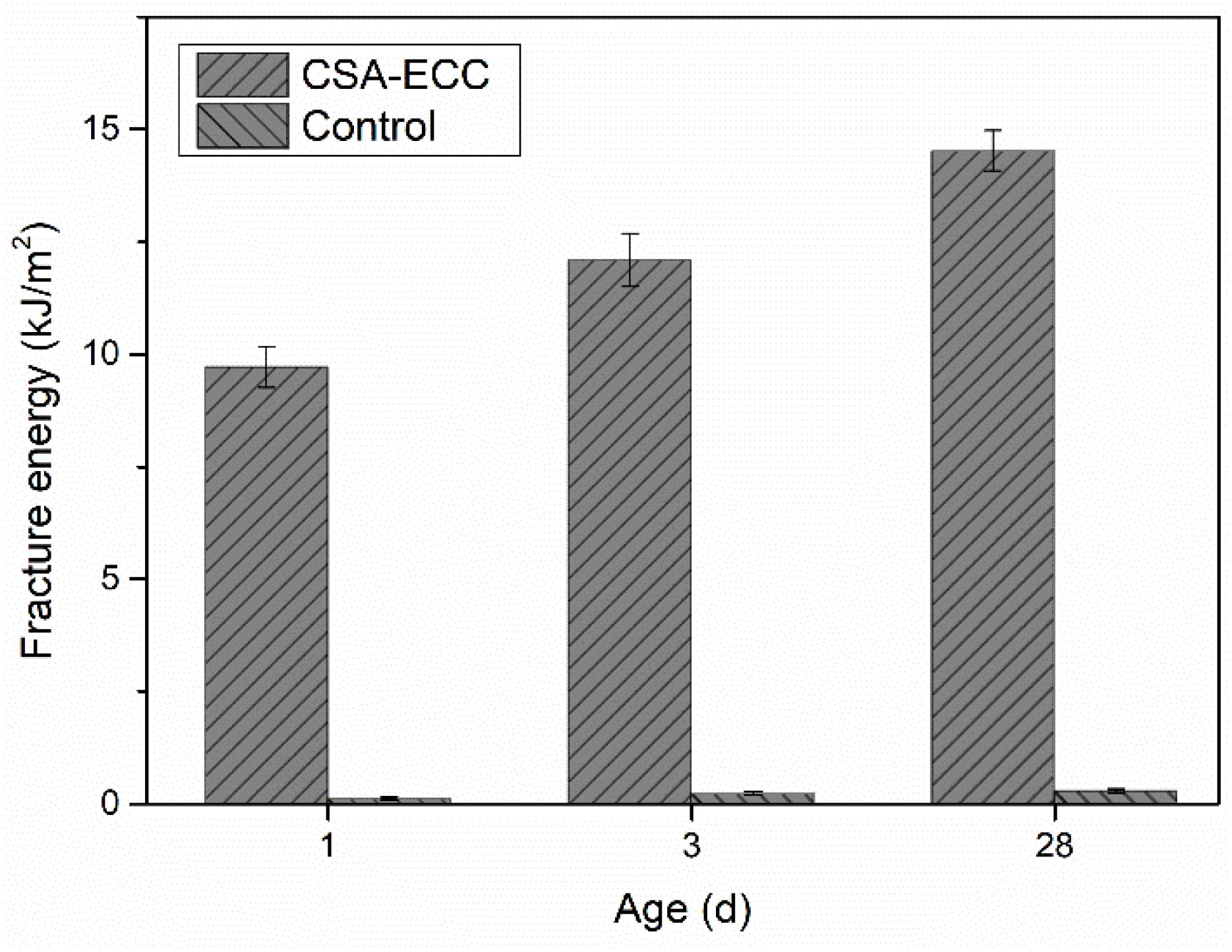
Figure 10. Calculated fracture energy of CSA-ECC and plain CSA specimens (control) after 1, 3, and 28 days of curing.
Tensile Properties
Figure 11 presents the typical tensile stress-strain curves of the plain HB-CSA specimen (Control) at 28 day and CSA-ECC dog bone-shaped specimens after 1, 3, and 28 days of curing. The CSA-ECC specimens in all cases show a typical tensile strain hardening pattern. More than 1% of the tensile strain capacity can be achieved only after 1 day of curing. The strain capacity is remarkably enhanced with the increase of curing age while only a slight rise was characterized on the tensile strength. For example, about 4 MPa of tensile strength of CSA-ECC specimens has been obtained after 1 day of curing, and this value is 4.6 MPa at 28 day. Meanwhile, comparing with plain HB-CSA cement, the introduction of UHMWPE fibers improved the 28 day tensile strength over 40%, from 3.28 to 4.6 MPa.
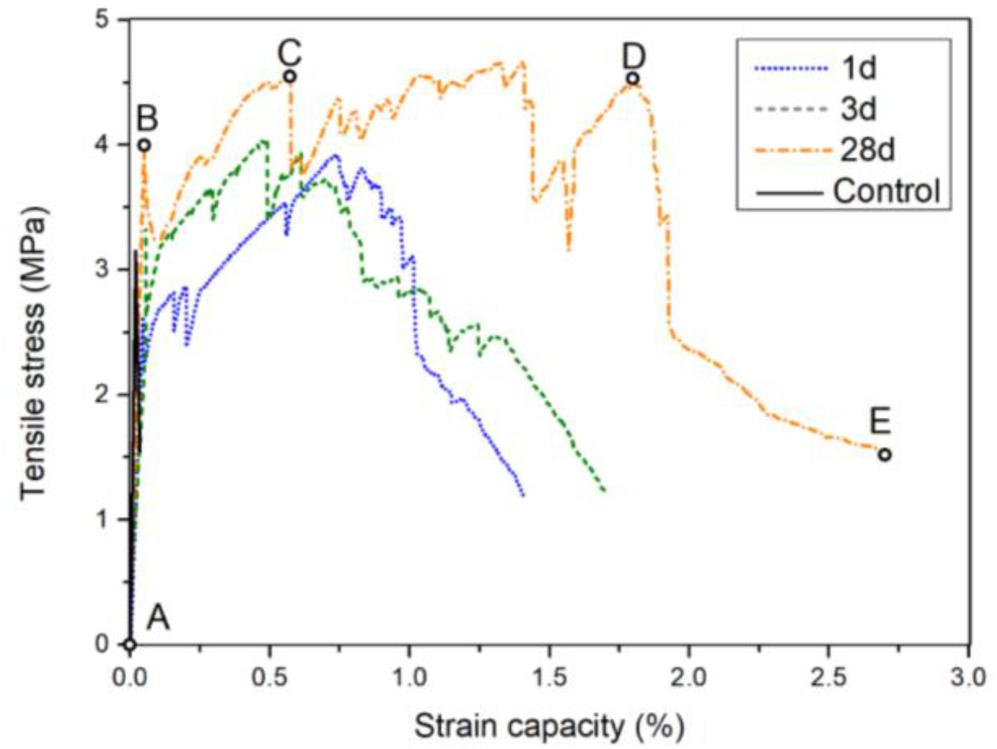
Figure 11. Tensile stress-strain curves of the plain HB-CSA specimen (control) and CSA-ECC dog bone-shaped specimens after 1, 3, 28 days of curing.
As shown, the development of the tensile stress-strain curve of CSA-ECC after 28 day of curing can be generally divided into four main stages. The first stage from A to B is the elastic stage. A linear stress-strain relationship was observed. The endpoint B represents that the first cracking strength of the HB-CSA matrix is 3.9 MPa. The fiber does not have any affect at this stage. In the second stage, the non-linear stress-strain curve between B and C is considered as the first crack developing stage. With the increase of the tensile stress, the CSA matrix has been completely fractured. Due to the bridging effect, the fibers which crossing the crack begin to undertake the loading until the stress reached point C. The stage between point C and point D is the multi-cracking strain hardening stage. During this stage, the stress was found fluctuated but slightly increased with the rise of stress. The fluctuation of the stress represents the occurrence of multi-cracking phenomenon. The endpoint D of this stage is corresponded to the ultimate tensile strength of the CSA-ECC material, where the maximal tensile strain capacity is 1.81%. This is about 90 times higher than the tensile strain capacity of plain HB-CSA cement, 0.02%. The final stage between D and F is the strain softening stage. The sharp decrease of stress at this stage implies that the crack bridging capacity of the UHMWPE fibers has been used up and a single main crack gradually formed. The dog bone specimens broke completely at point F. Table 6 summarized the key information obtained from the tensile strength test of the plain HB-CSA and CSA-ECC after 1, 3, and 28 day of curing.
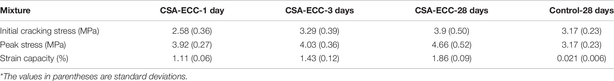
Table 6. Tensile test results of the CSA-ECC*.
Micro-Structure Analysis
Figure 12 shows the SEM images of UHMWPE fibers on the fracture surface of CSA-ECC. As can be seen from Figure 12a the UHMWPE fiber connected firmly with the cement matrix and no obvious crack can be found in the adjacent area. The UHMWPE fibers kept their appearance and functions after they were mixed and cured in CSA cement (Figure 12b).
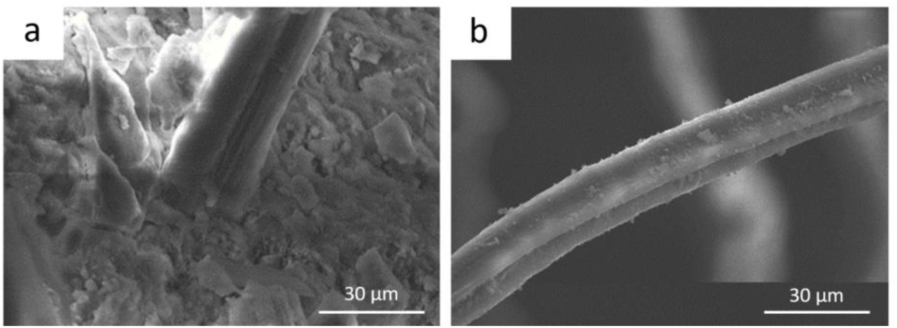
Figure 12. ESEM images of (a) the fiber-matrix connection area and (b) the morphology of UHMWPE.
Repairing Performance of CSA-ECC
Bonding Strength of CSA-ECC
The bonding strength between the CSA-ECC and the matrix is a key factor that will influence the repairing performance of CSA-ECC to concrete. Table 7 summarized the results of a three-point bending test of the two-halves specimens and mortar specimens at the age of 1, 3, and 28 days. As can be seen from the table, an average of 3.9 MPa of flexural strength can be reached for two-halves specimens only after 1 day of curing, which is significantly higher than that of pure mortar, 2.9 MPa. This result suggests that the CSA-ECC has an excellent bonding strength to the concrete once it was applied. With the increase of curing age, the bonding strength between CSA-ECC and mortar further increased. After 28 days of hydration, 4.6 MPa of flexural strength was realized for the two-halves specimens.

Table 7. Bonding strength results of two-halves and pure mortar specimens at the age of 1, 3, 7, and 28 days.
Flexural Strength Repaired Concrete Beam
Figure 13 shows the 28 day flexural strength of plain concrete beam and CSA-ECC coated concrete beam after 1, 3, and 28 days of repairing. It was found that the flexural strength of the repaired concrete beam has already reached 6.9 MPa only after 1 day of applying CSA-ECC on the concrete, which is 16.9% higher than that of plain concrete without repairment. This means that the CSA-ECC has a significant reinforcing performance even at the early age, which can be applied as rapid repairing agent for concrete structure restoration. With the increase of curing time, the flexural strength increased further to 7.1 MPa (3 day) and 8.2 MPa (28 day). Compared with plain concrete, the flexural strength enhanced by 20.3 and 39.0% at 3 and 28 days. The CSA-ECC repaired concrete beam obtains much higher flexural strength than its original form. This result suggests that the CSA-ECC has a good bonding strength with concrete matrix. When the repaired concrete beam was subjected to a vertical load, the repairing materials, CSA-ECC, became a part of the beam and shared the load together with the concrete matrix. Meanwhile, the CSA-ECC gave full play to its high toughness and ductility characteristics, preventing the occurrence and the development of cracking.
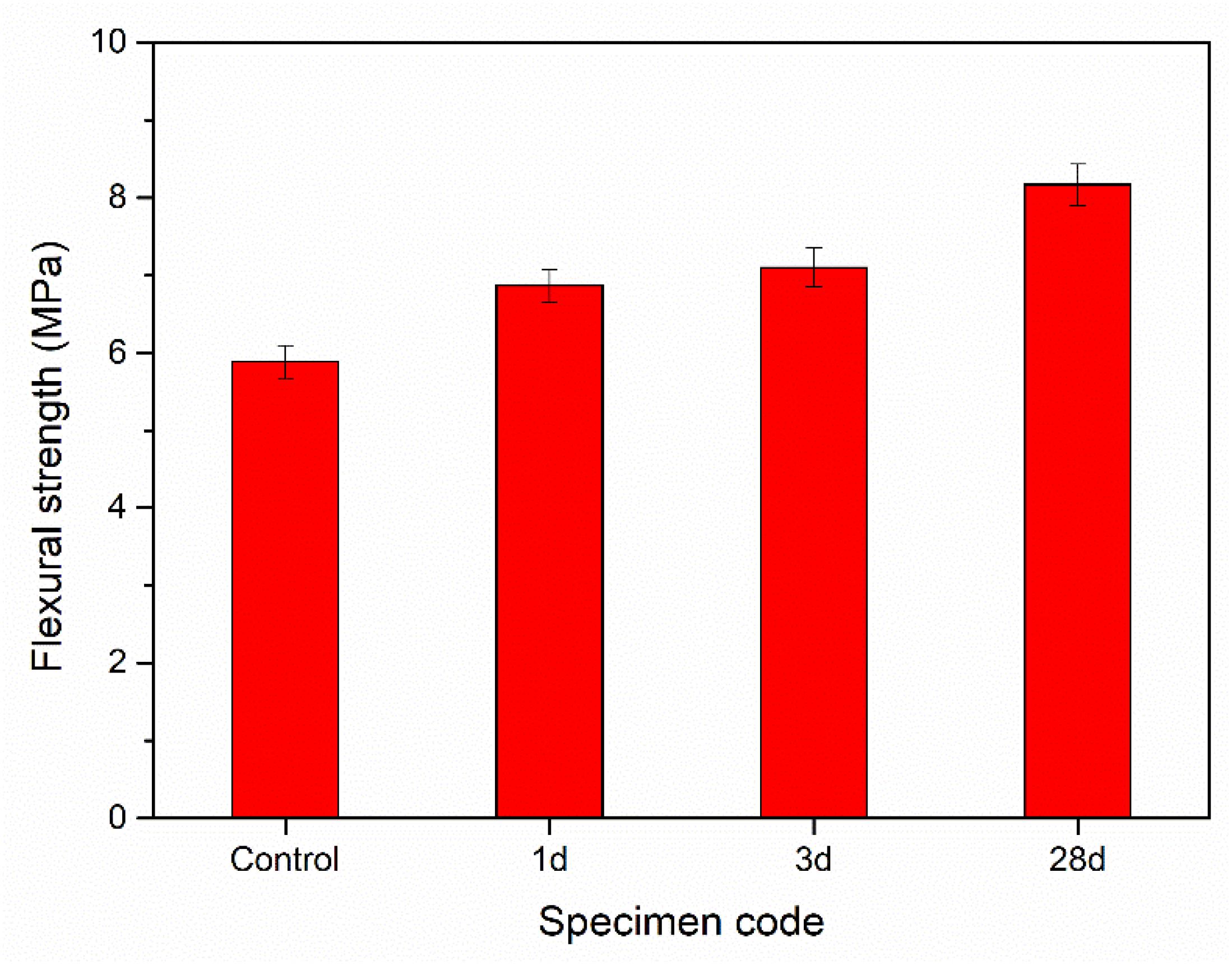
Figure 13. Flexural strength of plain concrete beam and concrete beam repaired with CSA-ECC for different age.
Compressive Strength of Repaired Concrete Column
Based on the load-displacement curve, the compressive strength of the repaired concrete column was calculated according to Eq. (2) and the results are shown in Figure 14. It can be seen from the figure that the repaired concrete column exhibits significant higher compressive strength than the plain concrete column (control). After only 1 day of repairing, the compressive strength of concrete column has already surpassed the compressive strength of the plain concrete column (46.85 MPa). With the increase of aging time, the compressive strength increased further from 54.72 MPa at 1 day to 59.12 MPa at 28 days. This result suggests that the CSA-ECC materials can be applied as an efficient and effective repairing material for concrete structure restoration. Figure 15 compared the damage morphology of the plain concrete column and CSA-ECC repaired concrete column. The damage pattern of CSA-ECC repaired concrete column is apparently different from the plain concrete column where only a single main crack was observed. In addition, it can be clearly seen from Figure 15B that no debonding phenomenon was characterized at the interlayer zone between the repairing agent and concrete matrix, representing that the CSA-ECC has a good binding effect with the concrete matrix. The CSA-ECC material wraps tightly on the concrete column, putting the concrete column under constrained state during the stress process, and thus significantly enhanced the axial compressive strength of concrete column.
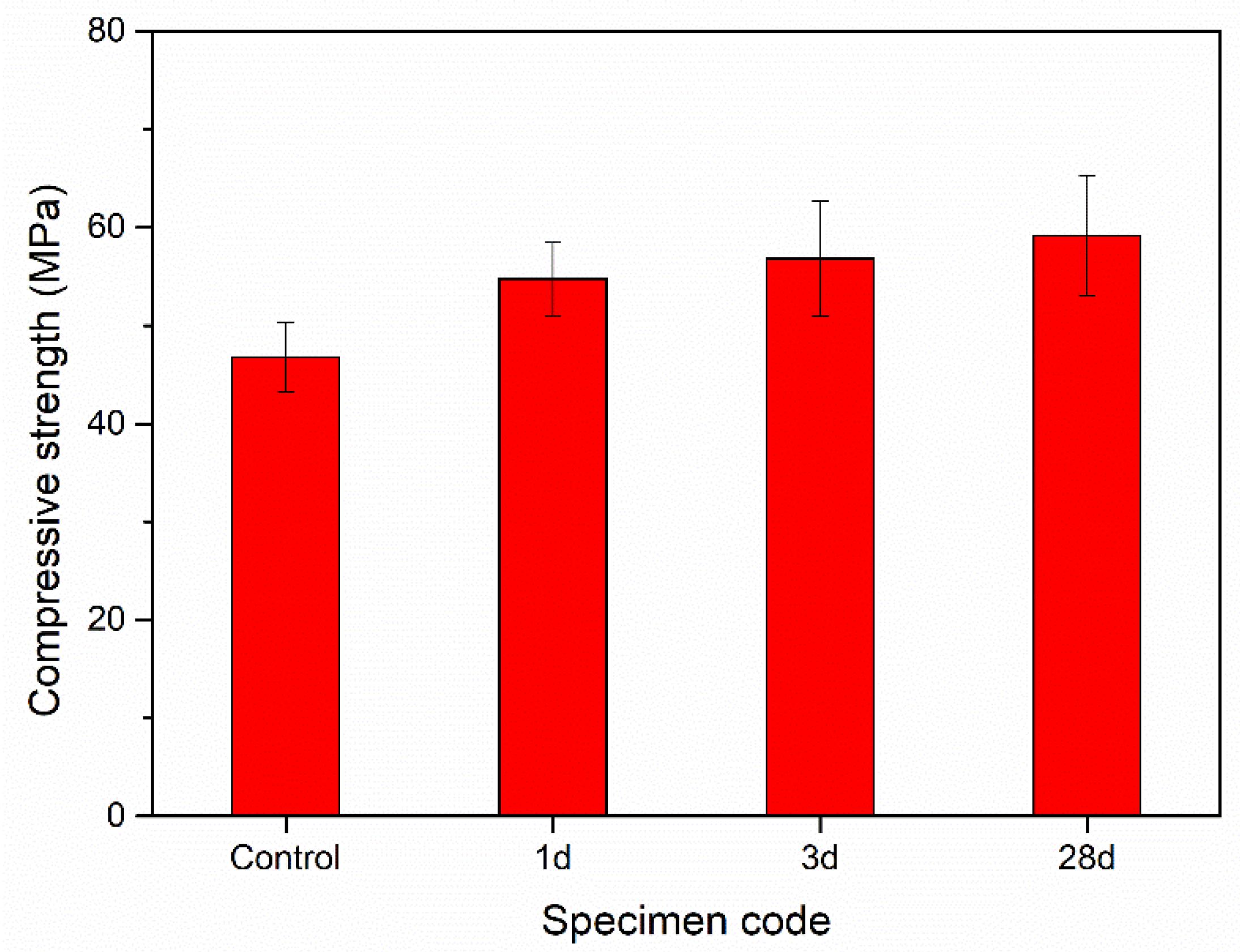
Figure 14. Compressive strength of plain concrete beam and concrete beam repaired with CSA-ECC for different age.
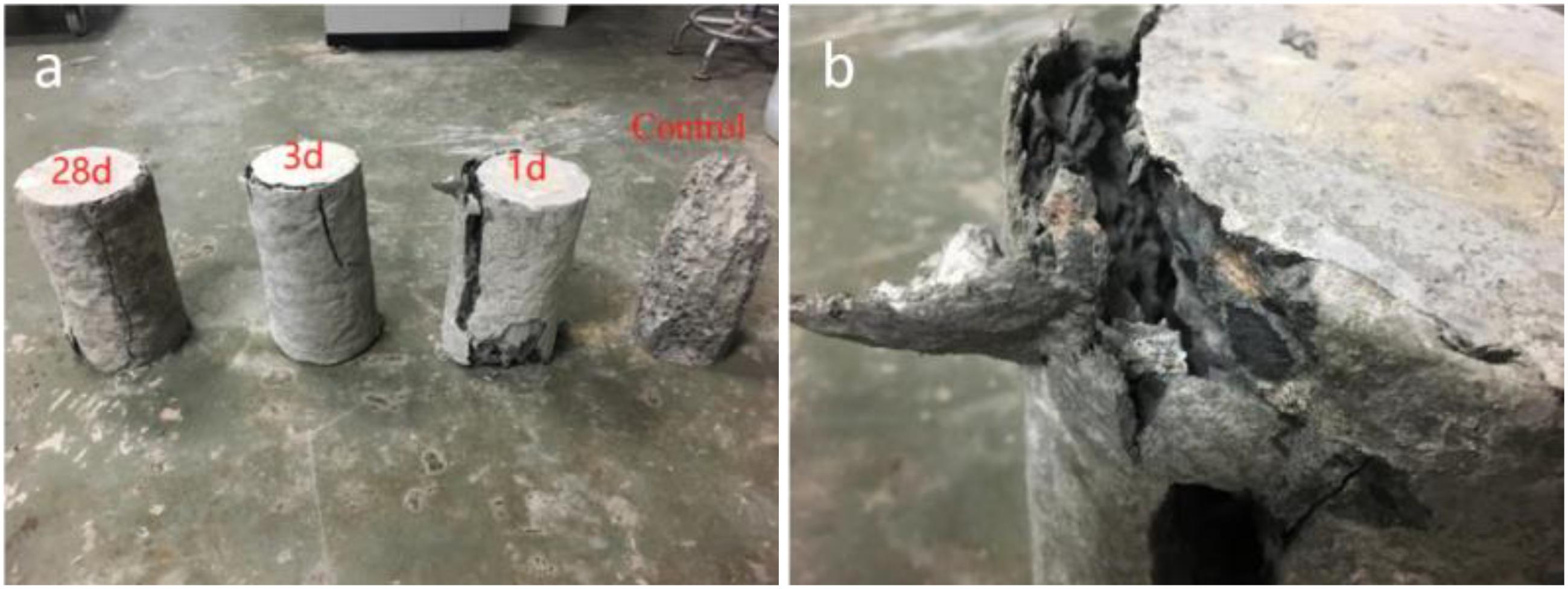
Figure 15. Images showing (a) the damage pattern of concrete column (b) the fracture zone of the column.
Conclusion
In this study, fast hardening and high early strength ECCs was developed by using HB-CSA as the matrix materials and UHMWPE fiber as reinforcement. The optimal mix design of CSA-ECC was determined in consideration of the cement to sand ratio, the proportion of additives, and the fiber content. After that, the performance of the prepared CSA-ECC material in concrete element repairing was characterized.
It was found that CSA cement incorporated with 2% PSP, 1% UHMWPE fiber, and with cement to sand ratio of two shows the best performance in the aspects of fluidity, flexural strength, and compressive strength. The fractured specimens presented a multi-crack effect. The cracking process of single notched CSA-ECC specimens under a three-point test show a typical yield hardening characteristic. The fracture energy of the CSA cement was found significantly improved with addition of UHMWPE fibers. In addition, the tensile strength and the strain capacity of HB-CSA cement can be greatly enhanced by properly mixing with UHMWPE fiber. The prepared CSA-ECC material shows an obvious strain-hardening behavior and possesses an ultra-high tensile strength capacity, which allows it to be adapted to rapid repairing of concrete where early strength, higher elongation, and smaller crack width are required. The SEM images show that the fiber bonds well within the CSA cement matrix, and no obvious crack was observed in the adjacent area, representing a good materials compatibility between the UHMWPE fiber and CSA material. Finally, the performance of CSA-ECC in concrete element repairing was characterized. The results suggest that the CSA-ECC materials has a good bonding strength with cement mortar and can be applied as an efficient and effective repairing agent for concrete structure restoration.
Additional research is needed to better understand the long-term performance of the CSA-ECC material during the employment at various conditions. Moreover, the behavior of the CSA-ECC materials in chloride resistance is needed to be explored.
Data Availability Statement
The raw data supporting the conclusions of this article will be made available by the authors, without undue reservation.
Author Contributions
LL and ZD conceived and designed the experiments. XH performed the experiments. All authors analyzed and discussed the data and wrote the manuscript.
Funding
The authors would like to acknowledge the financial support provided by the National Natural Science Foundation of China (No. 51908368) and Natural Science Foundation of Guangdong Province (2020A1515010939).
Conflict of Interest
XM was employed by company Guangdong Province Academy of Building Research Group Co., Ltd and HL was employed by China construction eighth engineering division. Co., Ltd.
The remaining authors declare that the research was conducted in the absence of any commercial or financial relationships that could be construed as a potential conflict of interest.
References
Afroughsabet, V., Biolzi, L., and Cattaneo, S. (2019). Evaluation of engineering properties of calcium sulfoaluminate cement-based concretes reinforced with different types of fibers. Materials 12:2151. doi: 10.3390/ma12132151
Bullerjahn, F., Boehm-Courjault, E., Zajac, M., Ben Haha, M., and Scrivener, K. (2019a). Hydration reactions and stages of clinker composed mainly of stoichiometric ye’elimite. Cement Concrete Res. 116, 120–133. doi: 10.1016/j.cemconres.2018.10.023
Bullerjahn, F., Zajac, M., Ben Haha, M., and Scrivener, K. L. (2019b). Factors influencing the hydration kinetics of ye’elimite; effect of mayenite. Cement Concrete Res. 116, 113–119. doi: 10.1016/j.cemconres.2018.10.026
Cao, W. Q., Fan, H., and Zhao, T. J. (2011). Performance properties of engineered cementitious composites (ECC) as concrete repair materials. Adv. Heterogeneous Mater. Mech. 2011, 1096–1099.
Guan, Y. H., Gao, Y., Sun, R. J., Won, M. C., and Ge, Z. (2017). Experimental study and field application of calcium sulfoaluminate cement for rapid repair of concrete pavements. Front. Struct. Civil Eng. 11, 338–345. doi: 10.1007/s11709-017-0411-0
Huang, X. Y., Ranade, R., Ni, W., and Li, V. C. (2013). On the use of recycled tire rubber to develop low E-modulus ECC for durable concrete repairs. Constr. Build. Mater. 46, 134–141. doi: 10.1016/j.conbuildmat.2013.04.027
Jacobs, G. T. A. J. (2010). Concrete Repairs: Performance in Service and Current Practice. Watford: IHS BRE Press.
Jen, G., Stompinis, N., and Jones, R. (2017). Chloride ingress in a belite-calcium sulfoaluminate cement matrix. Cement Concrete Res. 98, 130–135. doi: 10.1016/j.cemconres.2017.02.013
JSCE (2008). Recommendations for Design and Construction of High Performance Fiber Reinforced Cement Composites with Multiple Fine Cracks (HPFRCC). Tokyo: JSCE.
Kanda, T., and Li, V. C. (2006). Practical design criteria for saturated pseudo strain hardening behavior in ECC. J. Adv. Concrete Technol. 4, 59–78.
Leung, C. K. Y., Cheung, Y. N., and Zhang, J. (2007). Fatigue enhancement of concrete beam with ECC layer. Cement Concrete Res. 37, 743–750. doi: 10.1016/j.cemconres.2007.01.015
Li, M., and Li, V. C. (2011). High-early-strength engineered cementitious composites for fast, durable concrete repair-material properties. Aci. Mater. J. 108, 3–12.
Li, V. C., Horii, H., Kabele, P., Kanda, T., and Lim, Y. M. (2000). Repair and retrofit with engineered cementitious composites. Eng. Fract. Mech. 65, 317–334. doi: 10.1016/s0013-7944(99)00117-4
Li, V. C., Wang, S. X., and Wu, C. (2001). Tensile strain-hardening behavior of polyvinyl alcohol engineered cementitious composite (PVA-ECC). Aci. Mater. J. 98, 483–492.
Liao, Y., Wei, X., and Li, G. (2011). Early hydration of calcium sulfoaluminate cement through electrical resistivity measurement and microstructure investigations. Constr. Build. Mater. 25, 1572–1579. doi: 10.1016/j.conbuildmat.2010.09.042
Lim, Y. M., and Li, V. C. (1997). Durable repair of aged infrastructures using trapping mechanism of engineered cementitious composites. Cement Concrete Composites 19, 373–385. doi: 10.1016/s0958-9465(97)00026-7
Liu, H., Zhang, Q., Gu, C., Su, H., and Li, V. C. (2016). Influence of micro-cracking on the permeability of engineered cementitious composites. Cement Concrete Composites 72, 104–113. doi: 10.1016/j.cemconcomp.2016.05.016
Liu, H. Z., Zhang, Q., Li, V., Su, H. Z., and Gu, C. S. (2017). Durability study on engineered cementitious composites (ECC) under sulfate and chloride environment. Constr. Build. Mater. 133, 171–181. doi: 10.1016/j.conbuildmat.2016.12.074
Luo, Z. G., Lei, X. P., Zhou, Z. F., Liu, Y., and Lai, Y. (2013). Testing research on application of rapid-hardening sulphoaluminate concrete in rapid repair engineering for airport pavement. Prog. Ind. Civil Eng. 405-408, 1028–1031. doi: 10.4028/www.scientific.net/amm.405-408.1028
Moradi-Marani, F., Shekarchi, M., Dousti, A., and Mobasher, B. (2010). Investigation of corrosion damage and repair system in a concrete jetty structure. J. Perform. Construct. Facil. 24, 294–301. doi: 10.1061/(asce)cf.1943-5509.0000112
Parker, F., and Lee Shoemaker, W. (1991). PCC pavement patching materials and procedures. J. Mater. Civil Eng. 3, 29–47. doi: 10.1061/(asce)0899-1561(1991)3:1(29)
Recommendation, R. D. (1985). Determination of the fracture energy of mortar and concrete by means of three-point bend tests on notched beams. Mater. Struct. 18, 287–290. doi: 10.1007/bf02472918
Sahmaran, M., and Li, V. C. (2009). Durability properties of micro-cracked ECC containing high volumes fly ash. Cement Concrete Res. 39, 1033–1043. doi: 10.1016/j.cemconres.2009.07.009
Sirtoli, D., Wyrzykowski, M., Riva, P., Tortelli, S., Marchi, M., and Lura, P. (2019). Shrinkage and creep of high-performance concrete based on calcium sulfoaluminate cement. Cement Concrete Composites 98, 61–73. doi: 10.1016/j.cemconcomp.2019.02.006
Tang, Y., Fang, S., Chen, J., Ma, L., Li, L., and Wu, X. (2020). Axial compression behavior of recycled-aggregate-concrete-filled GFRP–steel composite tube columns. Eng. Struct. 216:110676. doi: 10.1016/j.engstruct.2020.110676
Van Belleghem, B., Kessler, S., Van den Heede, P., Van Tittelboom, K., and De Belie, N. (2018). Chloride induced reinforcement corrosion behavior in self-healing concrete with encapsulated polyurethane. Cement Concrete Res. 113, 130–139. doi: 10.1016/j.cemconres.2018.07.009
Wang, J.-Y., Chen, Z.-Z., and Wu, K. (2019). Properties of calcium sulfoaluminate cement made ultra-high performance concrete: tensile performance, acoustic emission monitoring of damage evolution and microstructure. Constr. Build. Mater. 208, 767–779. doi: 10.1016/j.conbuildmat.2019.03.057
Winnefeld, F., and Barlag, S. (2010). Calorimetric and thermogravimetric study on the influence of calcium sulfate on the hydration of ye’elimite. J. Therm. Anal. Calorimetry 101, 949–957. doi: 10.1007/s10973-009-0582-6
Winnefeld, F., Hargis, C. W., Steiner, S., Kaufmann, J., Borgschulte, A., Marchi, M., et al. (2018). “Carbonation resistance of calcium sulfoaluminate cement mortars,” in Proceedings of the Conference to Celebrate the Centennial of LMC and Karen Scrivener’s 60th Birthday, Lausanne, 243–246.
Xiong, Z., Cai, Q., Liu, F., Li, L., and Long, Y. (2020). Dynamic performance of RAC-filled double-skin tubular columns subjected to cyclic axial compression. Constr. Build. Mater. 248:118665. doi: 10.1016/j.conbuildmat.2020.118665
Yang, J. Y., Guo, Y. C., Shen, A. Q., Chen, Z. H., Qin, X., and Zhao, M. (2019). Research on drying shrinkage deformation and cracking risk of pavement concrete internally cured by SAPs. Constr. Build. Mater. 227:116705. doi: 10.1016/j.conbuildmat.2019.116705
Keywords: calcium sulfoaluminate cement (CSA), engineered cementitious composite (ECC), repairing agent, concrete member, UHMWPE fiber
Citation: Lv L, Hong X, Ding Z, Ma X and Li H (2020) Preparation and Characterization of Calcium Sulfoaluminate Based Engineered Cementitious Composites for Rapid Repairing of Concrete Member. Front. Mater. 7:282. doi: 10.3389/fmats.2020.00282
Received: 23 June 2020; Accepted: 27 July 2020;
Published: 11 September 2020.
Edited by:
Long-yuan Li, University of Plymouth, United KingdomReviewed by:
Ru Mu, Hebei University of Technology, ChinaYunchao Tang, Zhongkai University of Agriculture and Engineering, China
Copyright © 2020 Lv, Hong, Ding, Ma and Li. This is an open-access article distributed under the terms of the Creative Commons Attribution License (CC BY). The use, distribution or reproduction in other forums is permitted, provided the original author(s) and the copyright owner(s) are credited and that the original publication in this journal is cited, in accordance with accepted academic practice. No use, distribution or reproduction is permitted which does not comply with these terms.
*Correspondence: Zhu Ding, emRpbmdAc3p1LmVkdS5jbg==