 Zhiheng Hu
 Xiaoqing Zhou
 Menghuan Guo2
- 1College of Civil and Transportation Engineering, Shenzhen University, Shenzhen, China
- 2Guangdong Provincial Key Laboratory of Durability for Marine Civil Engineering, Shenzhen University, Shenzhen, China
Reinforced concrete (RC) beams that are shear-strengthened by externally bonded (EB) fiber reinforced polymer (FRP) often offer limited structural enhancement. This is due to the inherent weaknesses of EB-FRP strengthening, including the premature debonding of the FRP, its brittle rupture, and inadequate deformation capacity of the strengthening system. In this paper, two techniques of shear strengthening using U-wrapped carbon FRP (CFRP) and effective anchoring devices are proposed and tested with the aim of enhancing both the shear strength and the ductility of retrofitted RC beams. One of the techniques involves a hybrid-bonded (HB) CFRP system with adjustable normal pressure applied to the CFRP U-strips, and the other features the CFRP U-strips fastened by an H-type end anchor (EA). The main test variables of the former and latter shear-strengthening systems are the degree of pressure applied to the CFRP U-strips and the width of the deformation segment (or axial stiffness) of the H-type EA, respectively. The results indicate that both strengthening systems significantly enhanced the shear capacity and ductility of the strengthened RC beams. Compared with the control member, the increments in shear capacity were as high as 54.6 and 68.5% for beams retrofitted with the HB-FRP and the EA FRP systems, respectively, and their deflections at peak shear load increased by 43.9 and 84.1%, respectively. The shear failure modes were found to be related to the parameters used in both the HB-FRP and the EA FRP systems. The critical diagonal crack (CDC) inclination of all specimens was less than 45°, ranging from 38° to 44°. Both positive and negative shear interactions were observed between Vf and Vc plus Vs.
Introduction
The deterioration of existing reinforced concrete (RC) structures due to either increased loads or inadequate design (especially in old buildings constructed decades ago), which degrades the capacity of structures and severely threatens the safety of the structure, is becoming a significant issue. Over the past few decades, many approaches have been proposed to strengthen RC structures. Characterized by favorable features, e.g., a large strength-to-weight ratio, outstanding durability against environmental and mechanical effects, ease of application, tailorable materials, and geometric properties, fiber-reinforced polymer (FRP) has emerged in recent years as a popular means of strengthening structural components under different loads (Clarke, 2000; Neale, 2000; Teng et al., 2002, 2003; Karayannis and Sirkelis, 2008; Wu and Huang, 2008; Cao et al., 2018; Karayannis and Golias, 2018; Hu et al., 2019; Zhou A. et al., 2019; Zhou Y. W. et al. 2019; Zhou et al., 2020; Zhai et al., 2020).
In strengthening structures under different loads using FRPs, shear strengthening specifically is of practical significance due to two reasons. First, the shear failure of RC structures is brittle and sudden, which occurs without obvious signs and always leads to loss of life and property. A typical instance of this kind of failure is the shear failure of two air force warehouses in the US (ACI-ASCE Committee 326, 1962). Second, compared with flexural strengthening, the FRP shear strengthening of structures is a more challenging problem due to their inadequate bonding length and reduced ductility, as shown in Figure 1. To strengthen or retrofit RC beams in shear, externally bonded (EB) FRP is commonly utilized in the configuration of side-strip bonding and U-wrapping (Li and Leung, 2017; Zhou Y. W. et al., 2019). A large number of experiments and instances of practical use have shown that side-strip bonding leads to the premature debonding of FRP so that the retrofitting materials are not fully utilized, and the strength of the beams is only minutely enhanced (Teng et al., 2002). Although U-wrapping FRP technology performs better, the limitation of this configuration is that the bond length of FRP strips mostly depends on the section size of the RC beams (Chen and Teng, 2001). Thus, for shear strengthening, both the side-strip bonding and the U-wrapping of FRPs suffer from FRP debonding, which eventually results in the limited enhancement of the shear performance of retrofitted RC beams (Khalifa and Nanni, 2000; Deniaud and Cheng, 2003; Pellegrino and Modena, 2006; Mofidi and Chaallal, 2011; Colalillo and Sheikh, 2014; Chen et al., 2016; Li and Leung, 2017; Zhou Y. W. et al., 2019).
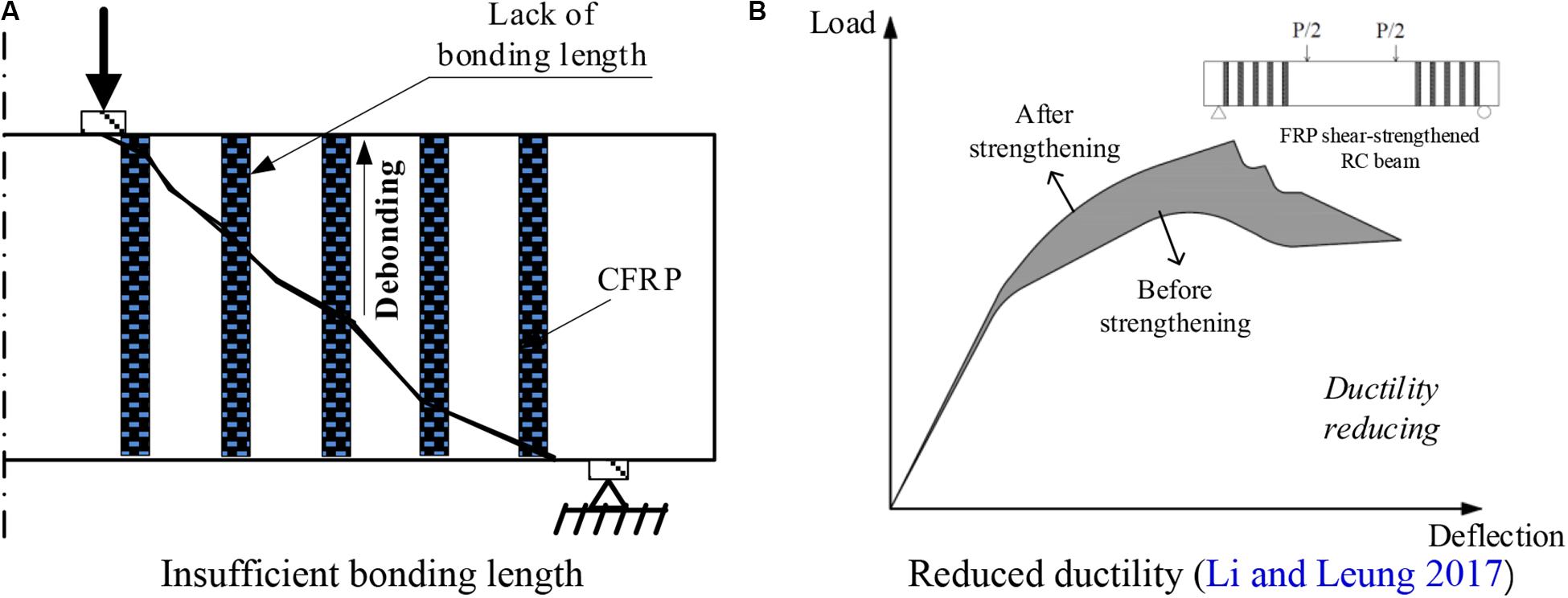
Figure 1. Problems of EB-FRP technology. (A) Insufficient bonding length. (B) Reduced ductility (Li and Leung, 2017).
Notably, there are two interfaces in the EB-FRP shear strengthening system which form the weakest links in the whole load-carrying and deformation system: an FRP–epoxy interface and a concrete–epoxy interface. If debonding failure occurs at these two positions, the FRP loses its efficacy before reaching its ultimate material strength, leading to the abrupt failure of the beam such that even partial transverse bars may not reach their yield strength (Wu and Huang, 2008; Zhou Y. W. et al., 2019). Therefore, in the chain reaction, the sudden and fracture interface failure triggers the so-called adverse shear interaction, which is the predominant factor causing the premature shear failure of FRP shear-strengthened RC beams (Chen et al., 2010, 2016).
To solve the problem of the weak interface of the EB–FRP bonding system, research has indicated that installing appropriate anchoring devices can effectively enhance the bonding strength of the FRP (Mofidi et al., 2012; Technical Report 55 [TR 55], 2012; Bae and Belarbi, 2013; National Research Council [CNR], 2013). In recent decades, various types of anchors have been developed, e.g., near-surface-mounted FRP (NSM-FRP) (De Lorenzis and Nanni, 2002), mechanically fastened FRP (MF-FRP) (Bank, 2004), hybrid-bonded FRP (HB-FRP) (Wu and Huang, 2008), FRP anchor fan (Smith et al., 2011), and the H-type end-anchored FRP (EA-FRP) (Zhou et al., 2018). A detailed description of FRP anchoring devices and their evaluations in terms of enhancing structural performance have been documented by Kalfat et al. (2013). Experimental and theoretical studies have demonstrated that both the HB-FRP (Wu and Huang, 2008; Wu et al., 2009, 2010) and the H-type EA-FRP strengthening systems (Zhou et al., 2017, 2018; Chen et al., 2018a,b) can significantly enhance the flexural strength and ductility of the retrofitted members by increasing the material utilization of the FRP and enabling a gradual debonding process over an extended loading period.
Although it has been validated that both the HB-bonded FRP and the H-type EA FRP strengthening can enhance the flexural performance of RC beams, their effectiveness in terms of enhancing shear performance, particularly deformation capacity, has rarely been reported. The relevant studies have shown that the deformation of a beam exerts a profound influence on shear strength components of an RC beam (Hu and Wu, 2017, 2018; Wu and Hu, 2017). It is assumed that the increased FRP material utilization and gradual debonding contributed by these two FRP bonding systems can significantly influence the shear behaviors of retrofitted RC beams, e.g., deformation capacity, shear strength components of concrete (Vc), transverse reinforcement (Vs), the FRP (Vf), and their interactions. One major difficulty facing the investigation of the problem of shear behaviors is the non-neglectable scattering between test results and the predicted data as per proposed models (Fico et al., 2008; Perera et al., 2010; Mari et al., 2014; Rousakis et al., 2016). Therefore, enlarging the test database contributes to a thorough evaluation of the accuracy of the theoretical models, which is another motivation of the current experimental study.
In this study, the effectiveness of two kinds of FRP strengthening systems are investigated based on shear tests of ten RC beams. One is the H-type EA-FRP retrofitting system with different widths of the deformation section. Another one is a pressure-alterable HB-FRP retrofitting system with different normal pressures applied to CFRP U-strips. This research emphasizes the improvement in the deformation capacity of the CFRP shear-strengthened RC beam, and its effects on the load-deflection curves, critical load, FRP material utilization, the inclination of the critical diagonal crack (CDC), shear strength components and their possible interactions, and the mechanism of enhancement in ductility.
Experimental Program
Specimen Design
The experimental program involved ten RC beam specimens with identical geometric dimensions of 200 mm in width, 370 mm in depth, and 2400 mm in length. All specimens were tested under four-point bending, corresponding to a shear span-to-depth ratio (a/d) of 2. A sketch, including details of beams and the locations of the CFRP strips, is provided in Figure 2. The concrete cover for all beams was set to 30 mm. Longitudinal reinforcing bars at the bottom of the beam consisted of four normal steel bars with a diameter of 28 mm laid into two layers. Two steel bars with the same diameter were laid in one layer at the top of the beam. To guarantee that shear failure occurred at the target shear span where HB-bonded FRP and the H-type EA FRP shear-strengthening were applied, this shear span was reinforced by stirrups with a diameter of 6.5 mm and a spacing of 120 mm. Another shear span, however, was intensively reinforced by stirrups with a diameter of 16 mm and a spacing of 80 mm, as shown in Figure 2A. The RC beams were designed according to the Chinese design code for RC concrete structures (Ministry of Housing and Urban-Rural Development Republic of China [MOHURD], 2010).
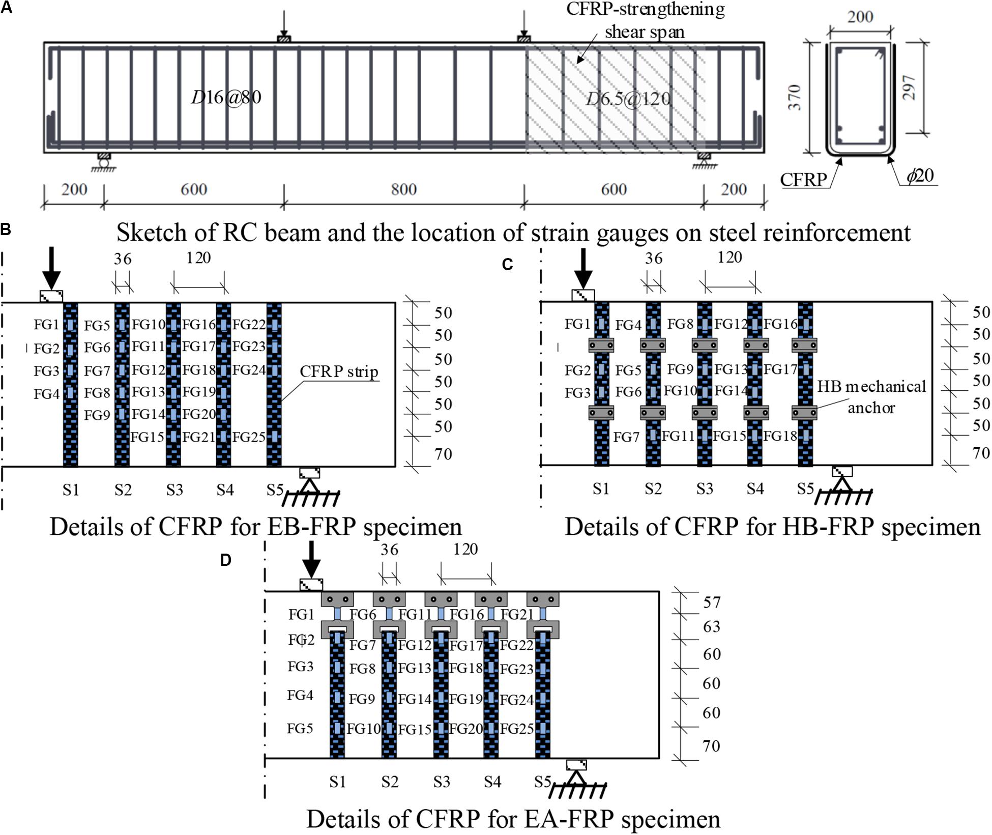
Figure 2. Details of specimens and the location of CFRP strip and strain gauges. (A) Sketch of RC beam and the location of strain gauges on steel reinforcement. (B) Details of CFRP for EB-FRP specimen. (C) Details of CFRP for HB-FRP specimen. (D) Details of CFRP for EA-FRP specimen.
The width and thickness of the U-CFRP strip were 36 mm and 0.167 mm, respectively. For the shear-strengthened specimens, five U-shaped CFRP strips were applied at the target shear span with a center-to-center spacing of 120 mm (Figures 2B–D). The central axis of the CFRP strips was set to be identical to that of the respective transverse bars. For the H-type EA-CFRP strengthening system, the anchor was fixed at the end of the CFRP strips, as illustrated in Figure 2D. For the HB-CFRP enhancing system, the locations of the anchors are marked in Figure 2C.
Each beam was labeled by a designation consisting of three letters, i-j-k, where i is the manner of shear strengthening, j represents the number of CFRP plies, and k denotes anchoring information. The letter i can be CB (control beam), EB, EA, and HB. The second letter j equals 0, 1, or 4. The third letter k can be 0, representing a beam without CFRP shear strengthening. In the HB-CFRP strengthening system, the value of k can also be 3, 6, or 12 N ⋅ m, denoting the torque moment applied on the mechanical fasteners. In terms of the H-type EA-CFRP retrofitting system, k can be 5, 7.5, 12.5, or 15 mm, signifying the width of the deformation section of the H-type anchorage. For example, CB-0-0, EB-1-0, and EB-4-0 denote the control beam without using any strengthening anchor, the specimen with one ply, and the specimen with four plies of U-shaped EB-CFRP shear strengthening, respectively. Specimen HB-1-6 represents the specimen strengthened by one-ply HB-CFRP under a moment of 6 N ⋅ m applied to the mechanical fasteners. Specimen EA-4-7.5 symbolizes a specimen retrofitted by the H-type EA-CFRP system with four plies of CFRP, with a deformation section that was 7.5 mm wide. The details of all specimens are summarized in Table 1.
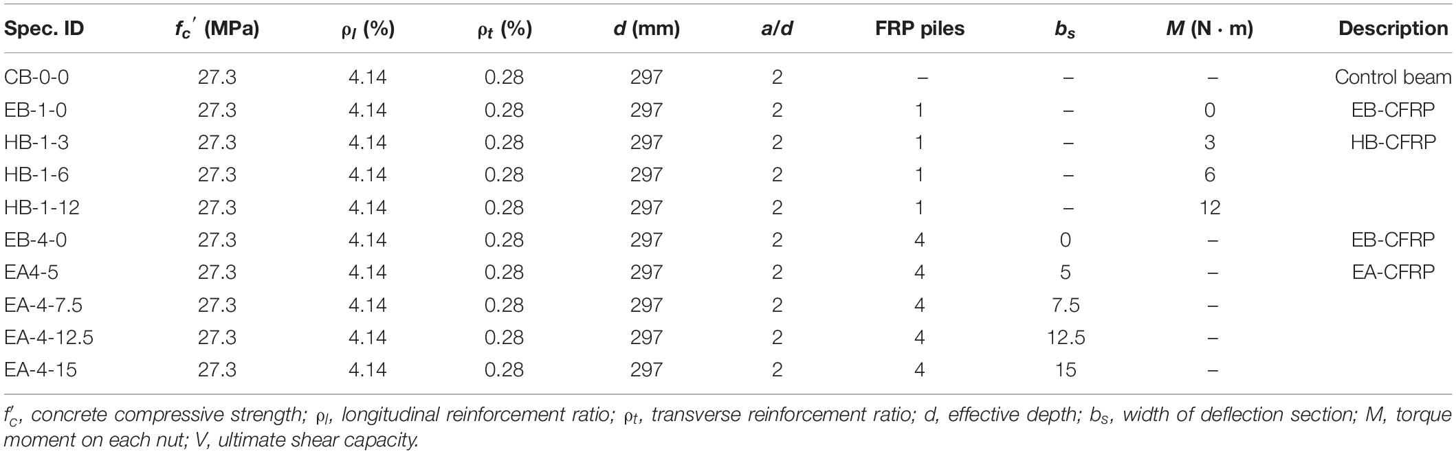
Table 1. Summary of specimens.
Anchoring Devices and Applying CFRP Shear Strengthening
The HB-CFRP system is composed of two capping steel plates with a thickness of 5 mm, two nuts, two washers, and two expansion screws. Figures 3A–C exhibit the details of the anchors used in the HB-CFRP strengthening system. The installment process was as follows: A hand-held vibrating needle scaler was first used to roughen the surfaces of the beam where the CFRP strips were to be bonded until the surface mortar had disappeared and coarse aggregates were exposed. After cleaning the treated surface, two holes, each with a diameter of 10 mm and a depth of 50 mm, were bored into the concrete to install the expansion screws. A layer of coat resin was smeared on the bonding region to seal the microcracks that had formed due to the coarsening. To avoid the stress concentration of CFRP strips at the two corners of the bottom of the beam, two round corners with a radius of 25 mm were made. Once the underlying resin had hardened, Lica®-100 A/B was applied as an adhesive between the CFRP strips and the concrete substrate. A day after the resin had dried, the anchorage was installed. The epoxy resin was infused into the drills to guarantee good bonding performance, and the expansion screws were subsequently hammered into the holes before the epoxy hardened. An extra coat of Lica®-100 A/B was brushed onto the stiff CFRP strips to improve contact with the capping steel plates. Two plates were placed at pre-determined locations and the washers were placed on them. The nuts were then tightened by a torque wrench until the target moment was reached before the epoxy hardened. Finally, the retrofitted specimens were cured at room temperature for seven days.
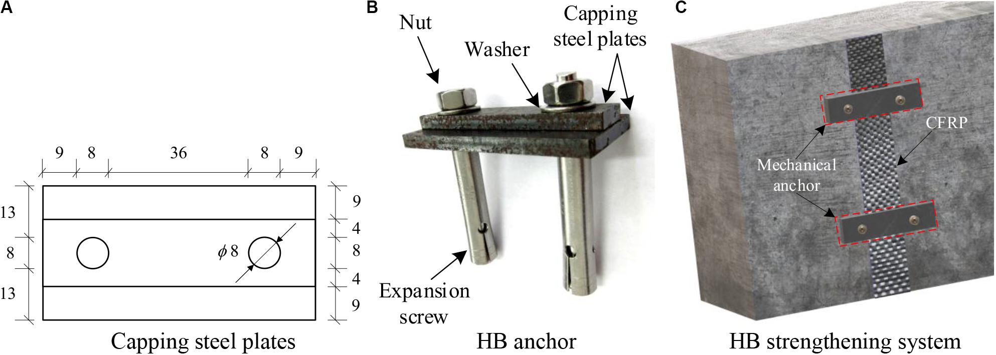
Figure 3. Details of HB-FRP system (units: mm). (A) Capping steel plates. (B) HB anchor. (C) HB strengthening system.
Figures 4A,B show the dimensions and details of the H-type EA. The thickness of all the H-type EAs was 5 mm. An H-type anchor consists of three parts: an anchorage section, a deformation section, and a connection part. For the H-type EA-CFRP strengthened beams, the treatment of the concrete surface was identical to that of the HB-CFRP system. Once the primer epoxy had hardened, the CFRP and H-type EAs were installed simultaneously, and the manner of pasting the CFPR strips and mounting the anchors was the same as that for the HB device. The most important part of the so-called H-type EA was the deformation section, designed to be 30 mm long. The axial load capacity and axial stiffness of the H-type EA were dominated by the width of the deformation section. Four plies of CFRP strips were used, aiming to guarantee that failure occurred in the EA device to sufficiently make use of the larger deformation capacity of the anchoring system.
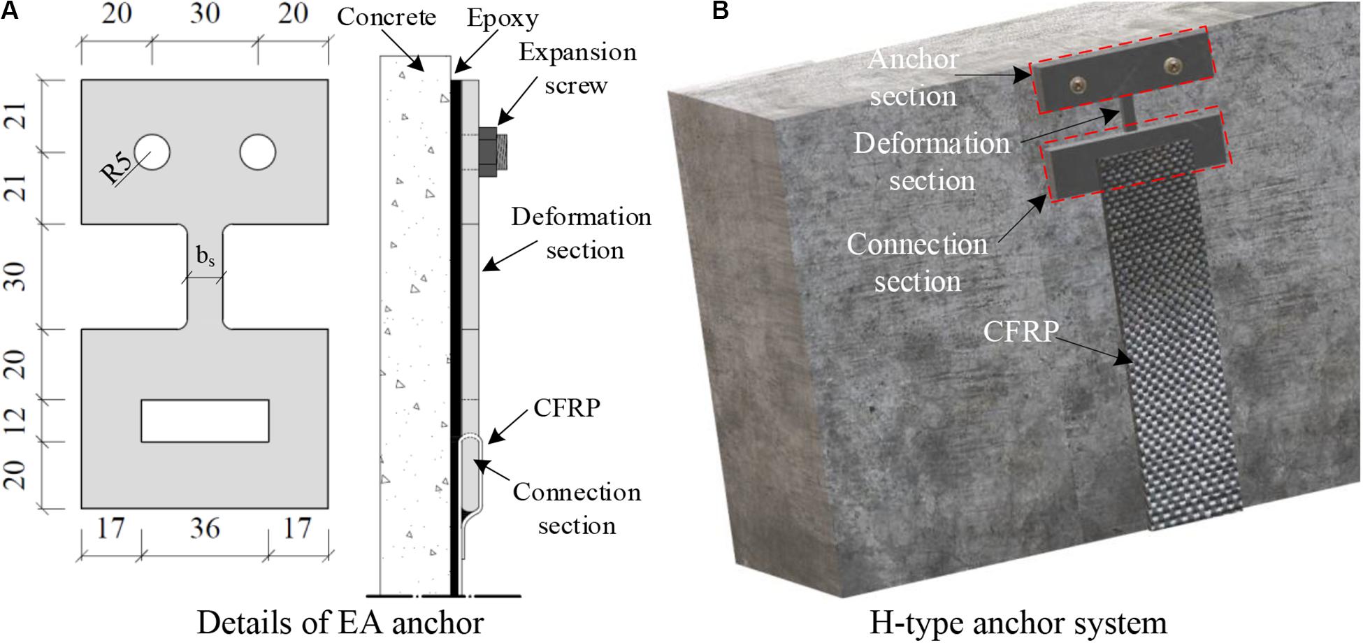
Figure 4. Details of H-type EA-FRP strengthening system (units: mm). (A) Details of EA anchor. (B) H-type anchor system.
Material Properties
The material properties of steel, concrete, and CFRP are summarized in Table 2. The designed compressive strength of concrete was 25 MPa. All concrete beams and concrete cubes were cured under the same conditions. Tests on the concrete cubes (100 mm × 100 mm × 100 mm) were conducted per ASTM C39/39M American society for testing and materials [ASTM], 2005 during the beam tests, and the average compressive strength of three typical cubes was 27.3 MPa. Per ASTM D3039/D3039M American society for testing and materials [ASTM], 2004, three samples of CFRP laminate were prepared and tested. All CFRP samples failed due to fiber breakage. The nominal thickness of a layer of CFRP strip was 0.167 mm. The tensile strength and Young’s modulus of the CFRP laminate and the epoxy were 4103 MPa and 270 GPa, and 46.9 MPa and 3300 GPa, respectively. Based on ASTM 370 American society for testing and materials [ASTM], 2012, standard coupon tests were conducted to obtain the mechanical properties of the reinforcing steel bars and anchoring steel plates.
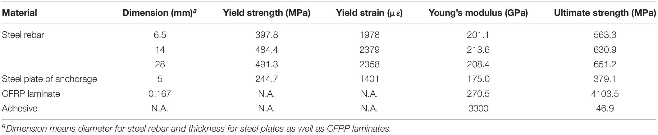
Table 2. Material properties.
Instruments and Test Setup
As shown in Figure 5, four-point bending tests were carried out by a 10000-kN MTS actuator, and the displacement control loading mode was adopted at a rate of 0.3 mm/min. Six linear variable differential transformers (LVDTs) were utilized to record the deflections of the beam and deformation of the supports. Strain gauges were installed on the longitudinal reinforcing bars and the CFRP strips, and were named LG and FG, respectively. As shown in Figures 2B–D, 25 FGs were on average distributed on the five CFRP strips for the EB- and EA-CFRP strengthened specimens, and 18 strain gauges for the HB-CFRP beams. For the HB-CFRP system, the strains of the CFRP strip were measured by strain gauges, while for the H-type EA-CFRP system, the strains of the CFRP strips and deformation segments of the EAs were monitored by strain gauges and a digital image correlation (DIC) system, respectively. The DIC is a non-contact strain measurement device that can be photographed and analyzed by the commercial software VIC-3D.
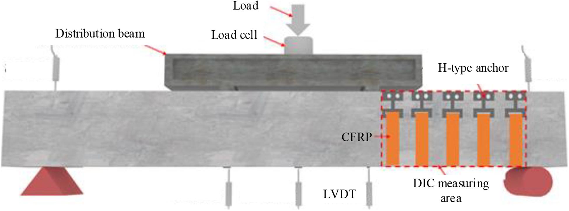
Figure 5. Test setup.
Experimental Results and Analysis
Cracking Pattern and Failure Modes
The typical cracking patterns of the tested specimens are shown in Figure 6. For the HB-CFRP strengthened beams (Figures 6B–D), their failures were controlled by crushing the concrete in the compressive zone beneath the loading point, and no flexural reinforcement yielding was monitored. This failure mode generally occurs in the case of the RC beams with a/d value around two: the so-called shear-compression failure. This failure mode has also been observed in unstrengthened and CFRP-strengthened RC beams elsewhere (Rousakis et al., 2016; Hu and Wu, 2017, 2018; Li and Leung, 2017). For all beams, the crack number, crack width, and length increased as the augment of the external load, which resulted in the debonding or rupture of the CFRP strips depending on the values of the torque moment applied. For CB-0-0 and EB-1-0, when the applied load reached about 95 kN, an initial shear crack generated in the target shear span. This diagonal crack subsequently extended along the line between the support point and the loading point with increasing shear force, led to the formation of the CDC. In the final stage of the loading process, several subordinate diagonal cracks appeared, accompanying the CDC. In addition, for EB-1-0, all CFRP strips debonded when the applied load approached the peak level, corresponding to the typical failure mode of a beam strengthened by the U-shaped wrapping of FRP, as has been observed in many other tests (Khalifa and Nanni, 2000; Deniaud and Cheng, 2003; Pellegrino and Modena, 2006; Mofidi and Chaallal, 2011; Colalillo and Sheikh, 2014; Li and Leung, 2017). This was mainly caused by the lack of bonding length of the FRP. For specimens HB-1-3 and HB-1-6, the cracking process was similar to that of EB-1-0, the debonding of the CFRP strips, but the debonding of the CFRP strips was much more gradual due to the interfacial frictional resistance provided by the applied normal pressure. The last specimen, HB-1-12, with the largest normal pressure applied on the CFRP strips, showed a different failure mode from the others. Some strips also debonded, while one of them ruptured where it intersected with the CDC, as shown in Figure 6D.
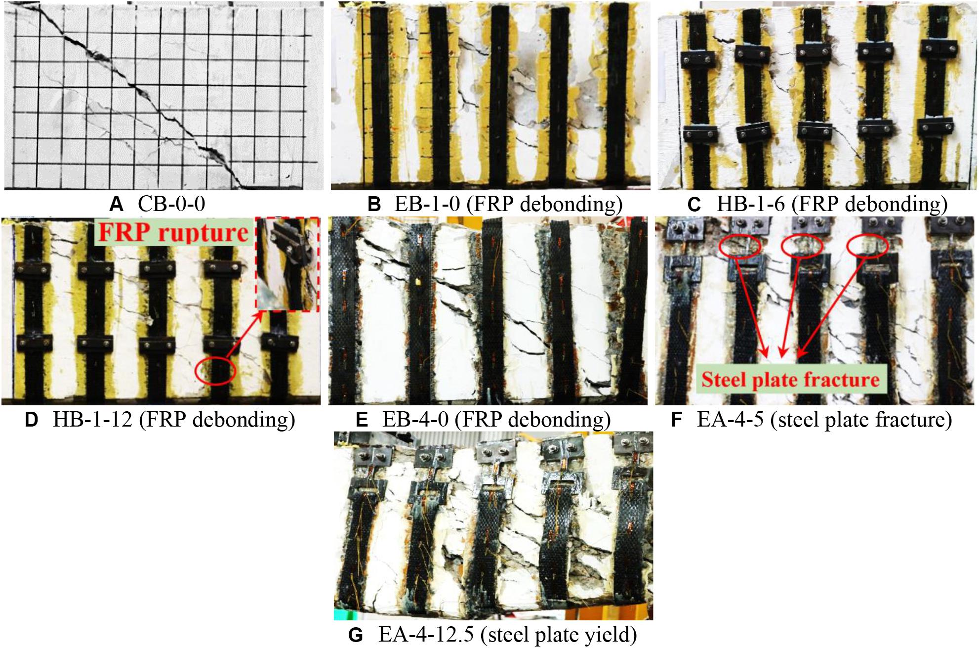
Figure 6. Typical failure modes of beam specimens. (A) CB-0-0. (B) EB-1-0 (FRP debonding). (C) HB-1-6 (FRP debonding). (D) HB-1-12 (FRP debonding). (E) EB-4-0 (FRP debonding). (F) EA-4-5 (steel plate fracture). (G) EA-4-12.5 (steel plate yield).
For the H-type EA-CFRP strengthening group, all five specimens failed in shear without the yielding of the longitudinal reinforcing bars (Figures 6E–G). The EB-4-0 ended in the typical failure mode as the conventional beam with the U-wrapping FRP without anchoring. Specimen EA-4-5 failed due to FRP debonding, and some of the anchors fractured in the deformation segment, as shown in Figure 6F. Specimens EA-4-7.5, EA-4-12.5, and EA-4-15.5 failed with CFRP debonding and the partial yielding of the deformation segments. The entire cracking and failure process was recorded by the DIC system. For EA-4-5, after the CDC had propagated through the compressive zone of the beam, the deformation segment of three H-type anchors ruptured after excessive inelastic straining and the external load reached its maximum value. As for the specimens equipped with wider deformation sections (7.5, 12.5, or 15 mm), the crushing of concrete in the compressive zone occurred, associated with the yielding of some deformation segments, and this eventually led to the shear failure of the retrofitted RC beams.
Load–Deflection Curves and Critical Loads
The shear force against the deflection curves of all tested beams in the two strengthening systems are shown in Figure 7. Two characteristic loads, the first shear cracking load (Vcr) and the peak shear force or shear capacity (V), identified from the curves are listed in Table 3 with their corresponding deflections. The method used to determine the value of Vcr was drawn from the literature (Wu and Hu, 2017; Hu and Wu, 2018).
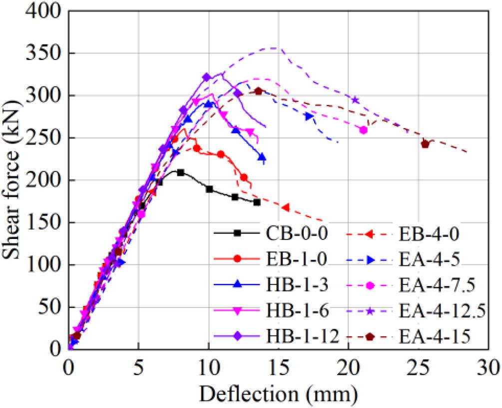
Figure 7. Shear force vs. deflection curves.

Table 3. Characteristic points of tested specimens.
For the HB-CFRP shear-strengthened beams (Figure 7B), before the occurrence of the first cracking, no apparent difference was observed in the load-deflection responses. When the first diagonal crack occurred, the slope of specimen CB-0-0 decreased while the other beams strengthened by the CFRP strips were affected insignificantly by the cracking. The values of Vcr summarized in Table 3 indicate that the first cracking load was postponed by the HB-CFRP strengthening, and a higher pressure applied to the CFRP strips resulted in a larger first shear cracking load. As the external load approached the maximum, the debonding of the CFRP strips occurred for the beam without anchorage (EB-1-0), and shortly after, the shear resistance declined suddenly and rapidly. For specimens HB-1-3, HB-1-6, and HB-1-9, the ultimate load increased gradually with the torque moment on the nuts, where this contributed to increasing the frictional forces between CFRP and concrete interfaces and allowed for the postponed and gradual debonding of the CFRP strips. Compared with the control specimen CB-0-0, the ultimate shear capacity increased by 23.8, 38.6, 43.3, and 54.6% for specimens under torque moments of 0, 3, 6, and 12 N ⋅ m, respectively. Wu and Huang (2008) elaborated on the mechanisms of this kind of anchor system as follows: (1) the additional bonding between the FRP and the steel capping plates, and (2) friction supplied by the screw with a specific torque moment. The first mechanism verifies that the extra adhesion is small (Wu and Huang, 2008). Therefore, the dominant mechanism must be frictional resistance. Only when the interfacial shear force caused by the externally applied load was larger than the shear resistance provided by the combination of the above mechanisms, the debonding of the FRP strip happens, such as in HB-1-3 and HB-1-6 (Figures 6C,D). If the anchoring device could provide enough interfacial resistance, the FRP would have ruptured and material could have been fully utilized, as was the case for HB-1-12 (Figure 6E).
For the H-type EA-CFRP retrofitted beams (Figure 7), the load-deflection curves showed a similar trend of variation to that of the HB-CFRP-strengthened beams. Before the formation of the first diagonal crack, all specimens exhibited a nearly identical load-deflection behavior. Compared with the control specimen CB-0-0, shear capacity increased by 11.9, 44.9, 51.6, 68.5, and 45.0% for beams with deformation segments that were 0, 5, 7.5, 12.5, and 15 mm wide, respectively. The significant increments in both shear capacity and deflection were provided by the anchoring effect of the EA-CFRP anchoring devices. Furthermore, the wider the deformation section was, the more the H-type anchor contributed to shear strength. As the FRP laminate was fastened by the end anchor, interfacial slip was restricted and the debonding of the FRP was postponed. The EA imposed little influence on the cracking force of the strengthened beams.
Angle of CDC
Many researchers (Chaallal et al., 1998; Chen and Teng, 2003a,b; Rousakis et al., 2016) have concluded that the angle of the CDC (θcr) and the inclination of the diagonal compressive concrete struts can strongly influence the variation and development of strain in the FRP, and subsequently, the shear contribution of FRP can eventually be affected. Additionally, the values of these two angles were not identical because of frictional forces at the interfaces of the cracks (Vecchio and Collins, 1986; Rousakis et al., 2008; Hu and Wu, 2017). However, it was difficult to distinguish the difference between these two angles, and a simplifying assumption was made that the angle of the principal compressive stress coincided with θcr if the difference between them was within a certain range (Vecchio and Collins, 1986). Therefore, the present study determined and evaluated the angle of the CDC to broaden the database θcr.
Two approaches were applied to determine and mutually confirm the path of the CDC, i.e., the visible CDC path observed in the tested specimen, and the linking of the points where the maximum strain in each CFRP strip was detected (Wu and Hu, 2017; Hu and Wu, 2018). The results of CDC inclination are summarized in Table 4. For the HB-CFRP system, the values of θcr were 38°, 40°, 41°, 43°, and 38° for CB-0-0, EB-1-0, HB-1-3, HB-1-6, and HB-1-12, respectively. For the EA-CFRP system, the values of θcr were 39°, 39°, 40°, 42°, and 44° for EB-4-0, EA-4-5, EA-4-7.5, EA-4-12.5, and EA-4-15, respectively. All the experimentally determined angles of the CDC were lower than 45°, different from what has been specified (i.e., 45°) in some design guidelines (Japan Society of Civil Engineers [JSCE], 2001; American Concrete Institute [ACI], 2008; Technical Report 55 [TR 55], 2012). The value of θcr increased with the normal pressure on the FRP strips, except in the case of HB-1-12. The presence of the torque moment on the CFRP strips increased the upper limit of the shear contribution of the CFRP, causing the angle of the CDC to increase, which is similar to the observations made by Jirawattanasomkul et al. (2013) and Chen et al. (2016). As to the H-type EA-FRP device, a similar trend was also observed due to the same reason.
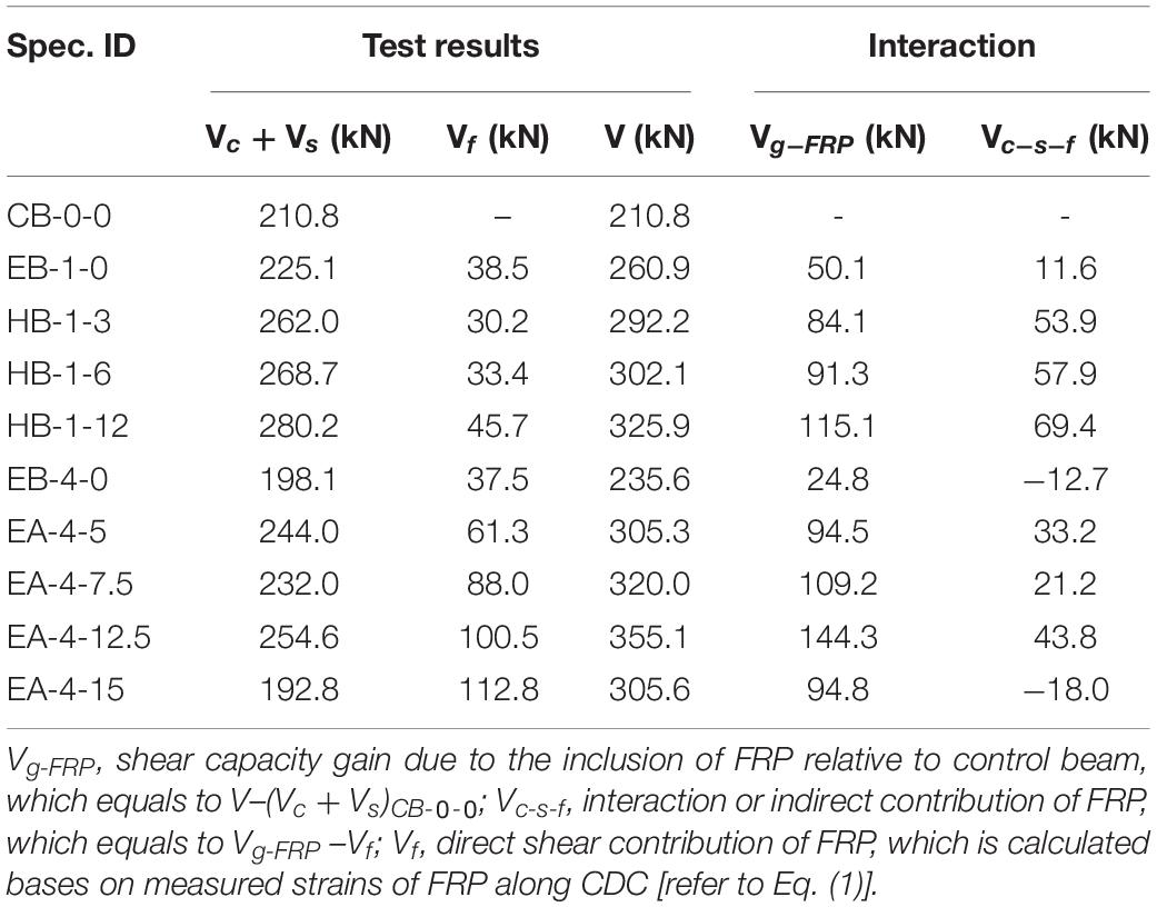
Table 4. Interaction between shear strength components.
Strain Development and Distribution in FRP Strips
The shear force against the CFRP strain for typical specimens anchored by the above stated two mechanical anchoring systems are depicted in Figures 8–11. The five FRP strips in a beam were denoted by S1, S2, S3, S4, and S5. Strip S1 was close to the loading point while S5 was near the support point, as shown in Figure 2. For both the HB-CFRP and the EA-CFRP systems, the locations and numbers of strain gauges are marked in Figure 2.
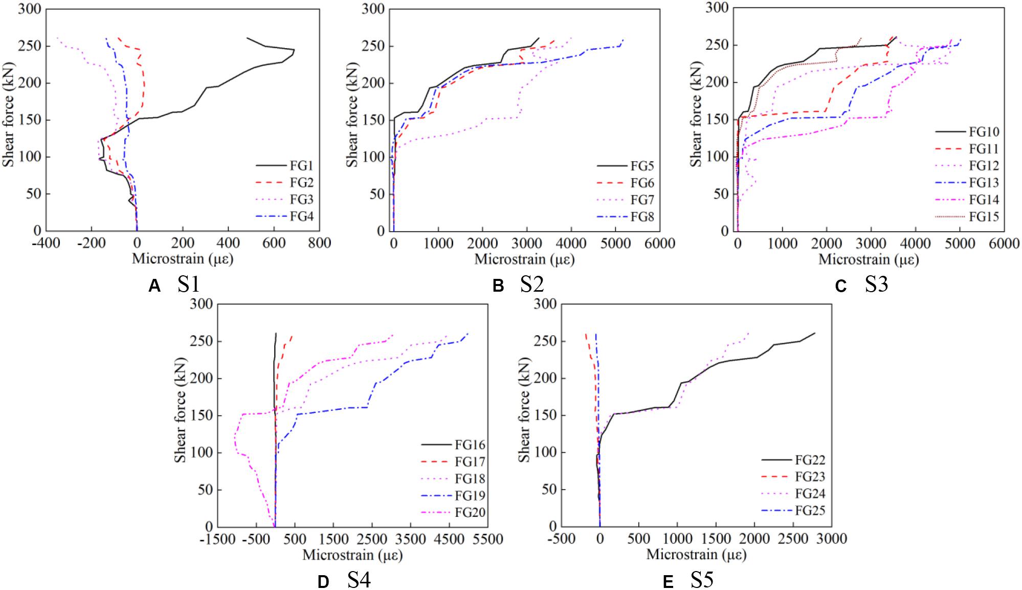
Figure 8. Strain development in CFRP strips for EB-1-0. (A) S1, (B) S2, (C) S3, (D) S4, and (E) S5.
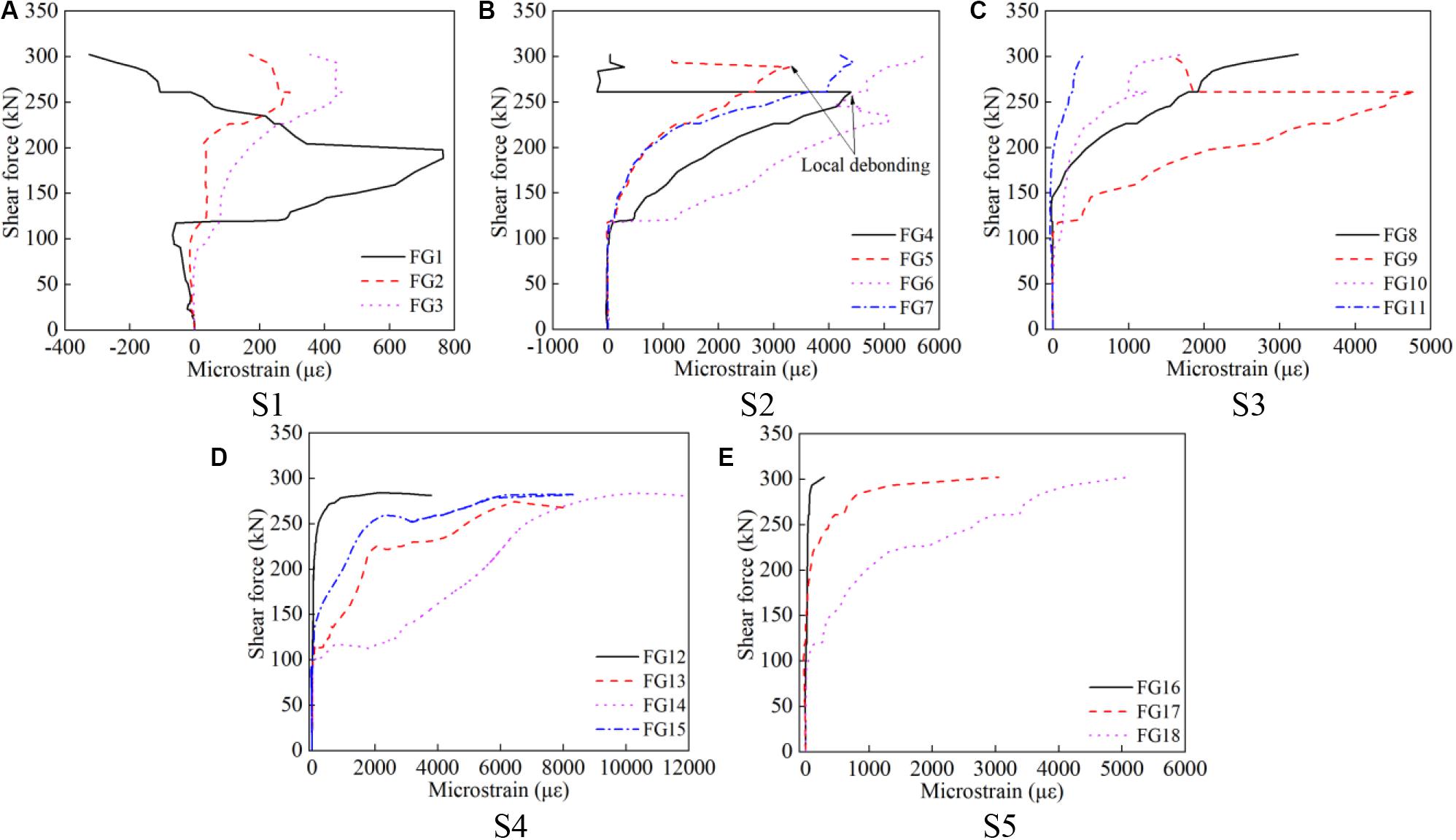
Figure 9. Strain development in CFRP strips for HB-1-6. (A) S1, (B) S2, (C) S3, (D) S4, and (E) S5.
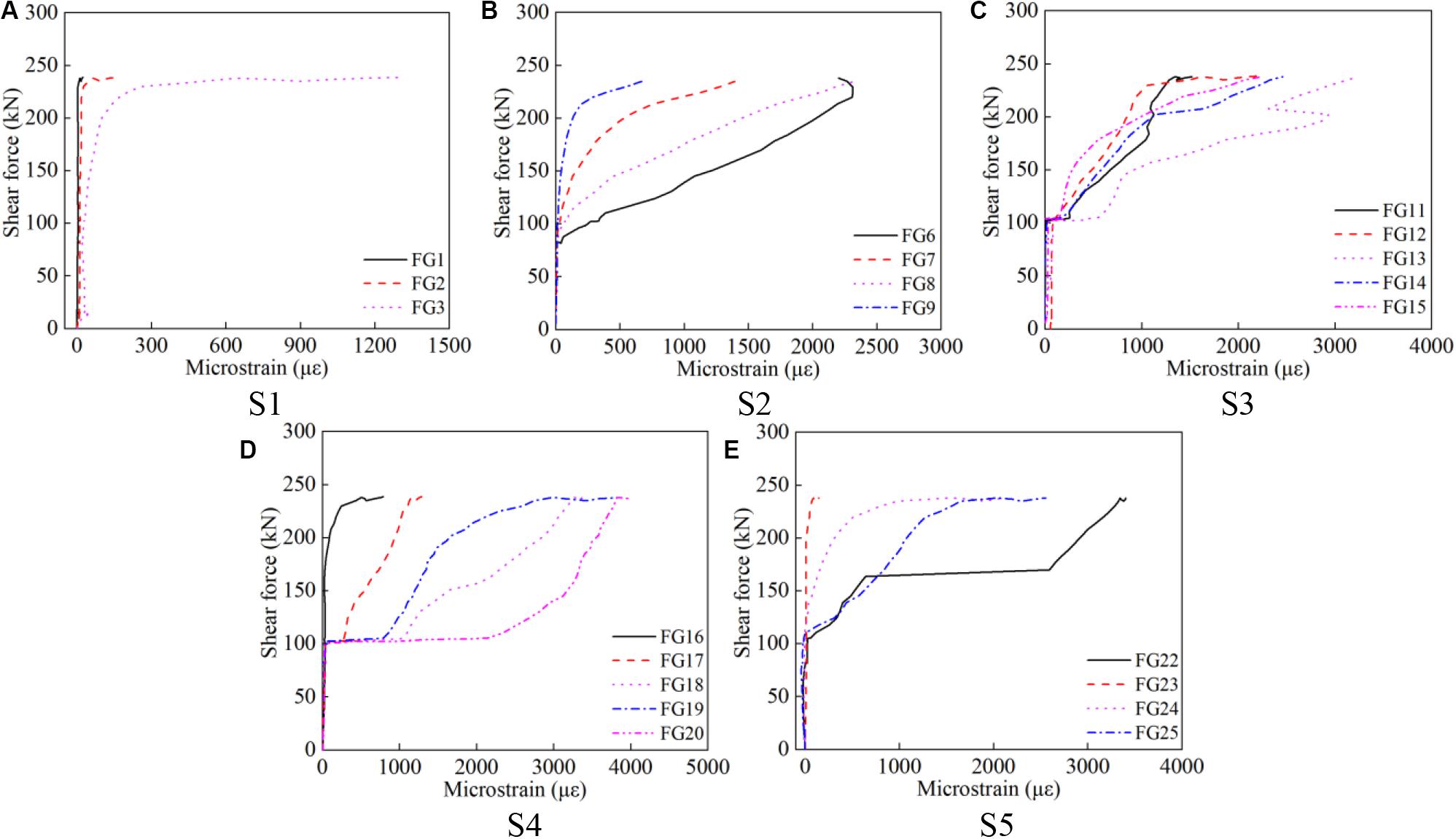
Figure 10. Strain development in CFRP strips for EB-4-0. (A) S1, (B) S2, (C) S3, (D) S4, and (E) S5.
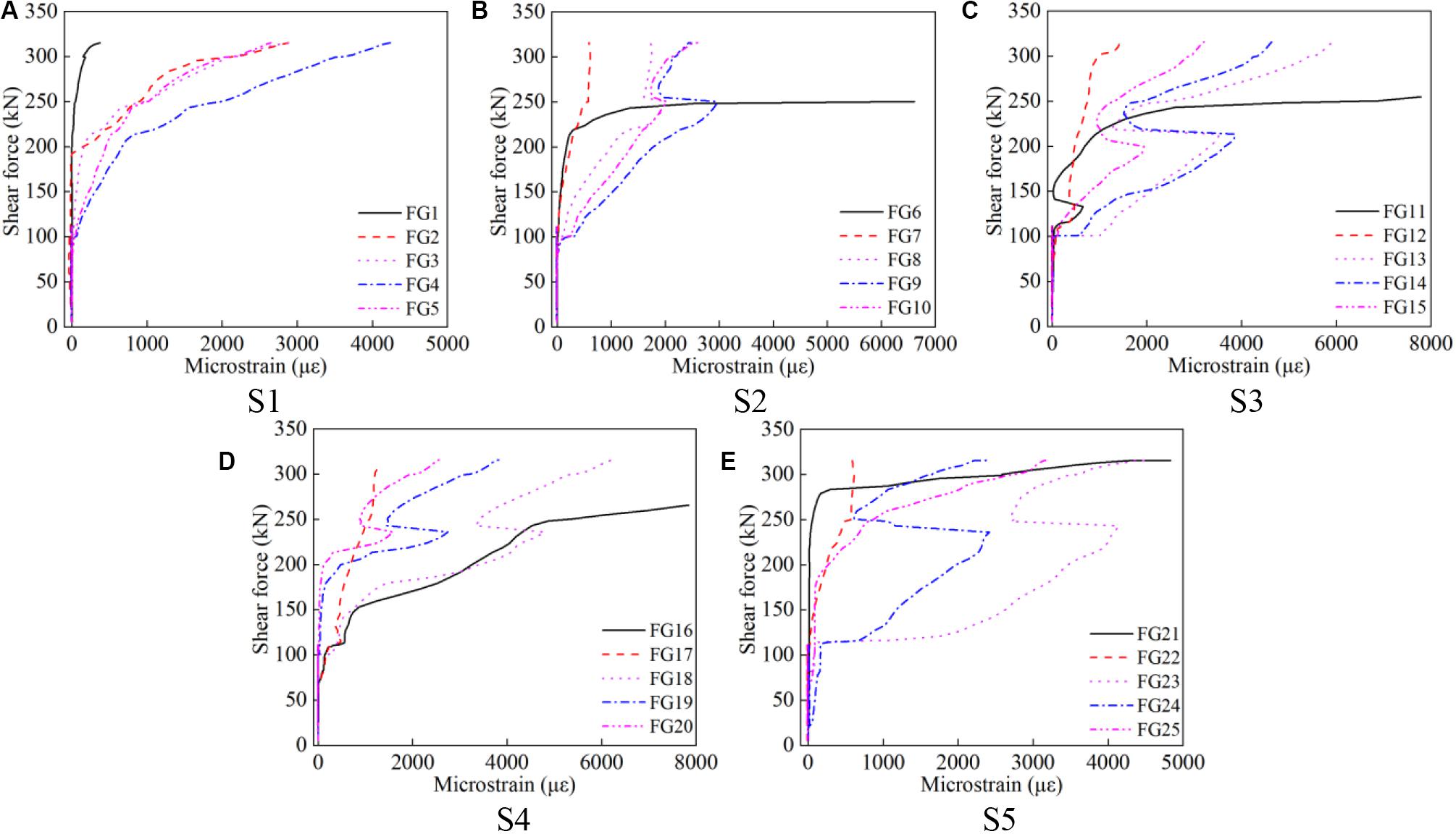
Figure 11. Strain development in CFRP strips for EA-4-5. (A) S1, (B) S2, (C) S3, (D) S4, and (E) S5.
It is clear that a three-stage response can be identified for all curves in Figures 8–11. Before the generation of the initial shear crack, there was almost no straining in the CFRP strips, demonstrating that the shear resistance of CFRP strips has not yet been activated. At this stage, shear resistance was contributed only by the concrete, with no contribution from either of the transverse bars (Wu and Hu, 2017; Hu and Wu, 2018) and the FRP (Bousselham and Chaallal, 2004, 2006; Chen et al., 2016; Li and Leung, 2017; Zhou Y. W. et al., 2019). With increasing load, the concrete was under the more profound combined action of flexural and shear stresses, leading to the formation of the diagonal crack in the shear span. When the first shear crack generated, the strain of the CFRP sheets increased sharply for all specimens (Figures 8–11), leading to a redistribution of stresses among the concrete, transverse bars, and CFRP strips. This shows that the shear contribution of the CFRP was active. The third stage is represented by the curve after the sudden increase in CFRP strain, which continuously rose at varying rates. The debonding of the CFRP strips happened at the end of this stage, when the external load neared the ultimate shear force of the beam. For the HB-enhancing system, the anchorage applied on the CFRP strips significantly improved the bonding strength between concrete and CFRP, which can be observed from the maximum value of CFRP strain. Furthermore, the improving effect got increasingly stronger with the increase of the normal pressure fastening the CFRP. For EB-1-0 and EB-4-0, the maximum strain was close to 5000 micro-strains (Figures 8, 10), and jumped to 8000, 10000, and 9000 micro-strains, respectively, for the HB-FRP system at torque moments of 3, 6, and 12 N ⋅ m, and to 6000, 7000, 12000, and 7000 micro-strains for the EA-CFRP system with deformation segments that were 5, 7.5, 12.5, and 15 mm wide, respectively.
For EB technology without any anchoring device, the specimen failed immediately after the debonding of the CFRP. Thus, the curves in Figures 8, 10 increased continually without the phenomenon of strain snap-back. Additionally, for EB-CFRP-strengthened beams, due to the debonding of the CFRP strips, a more significant drop in the load-carrying capacity occurred than that in the control beam, indicating that the EB-CFRP shear-strengthened beams (e.g., EB-1-0 and EB-4-0) were more brittle than the control beam CB-0-0 (Figures 1B, 6).
For specimens strengthened by the HB-CFRP system, a clear snap-back of strain appeared in the FRP strips in S2 and S3 (Figures 9B,C). The main reason for this phenomenon was the lack of effective bonding length, as indicated in Figure 1A. However, the debonding did not occur in S4 and S5 because of the combination of two factors: the friction provided by mechanical anchors and the relatively longer bonding length. For the H-type EA-CFRP system, a significant snap-back was observed in strips S2, S3, and S4 (Figure 11). Once local debonding had occurred, strain at the debonding position decreased rapidly and suddenly (Figures 11B–D). By comparing the development of CFRP strains between the RC beams with and without the mechanical anchor, the functions of the HB- and the H-type EA anchoring systems were examined and evaluated in detail. For the HB-CFRP system, the debonding of the CFRP could be delayed. Even though local debonding occurred, the sudden and total debonding of the CFRP strips can be prevented; instead, a gradual debonding process during a longer period can be achieved. For the H-type EA-CFRP shear-strengthened beams, local and global debonding did not result in failure owing to the ductile EAs. It can be observed that the snap-back of the CFRP strain took place at a load of around 250 kN, close to the shear capacity of the EB-CFRP shear-strengthened beams. After local debonding, the specimens with anchors were able to sustain further increases in load up to failure (Figures 9, 11).
The strain distribution along the height of the CFRP sheets at various load levels are depicted in Figures 12–15. For specimens EB-1-0 (Figures 12A,B) and EB-4-0 (Figures 14B,C), a slight local debonding was observed at about 0.95V. While for beams strengthened with HB-CFRP and H-type EA-CFRP, this phenomenon occurred at loads of around 0.85V, smaller than that of EB-CFRP-strengthened beams. The bond between the concrete substrate and the CFRP strips resulted in different strain values at any given position along the height of the CFRP strips.
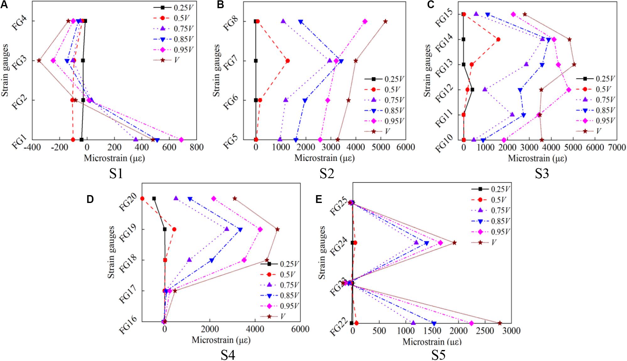
Figure 12. Strain distribution along the height of CFRP strips for EB-1-0. (A) S1, (B) S2, (C) S3, (D) S4, and (E) S5.
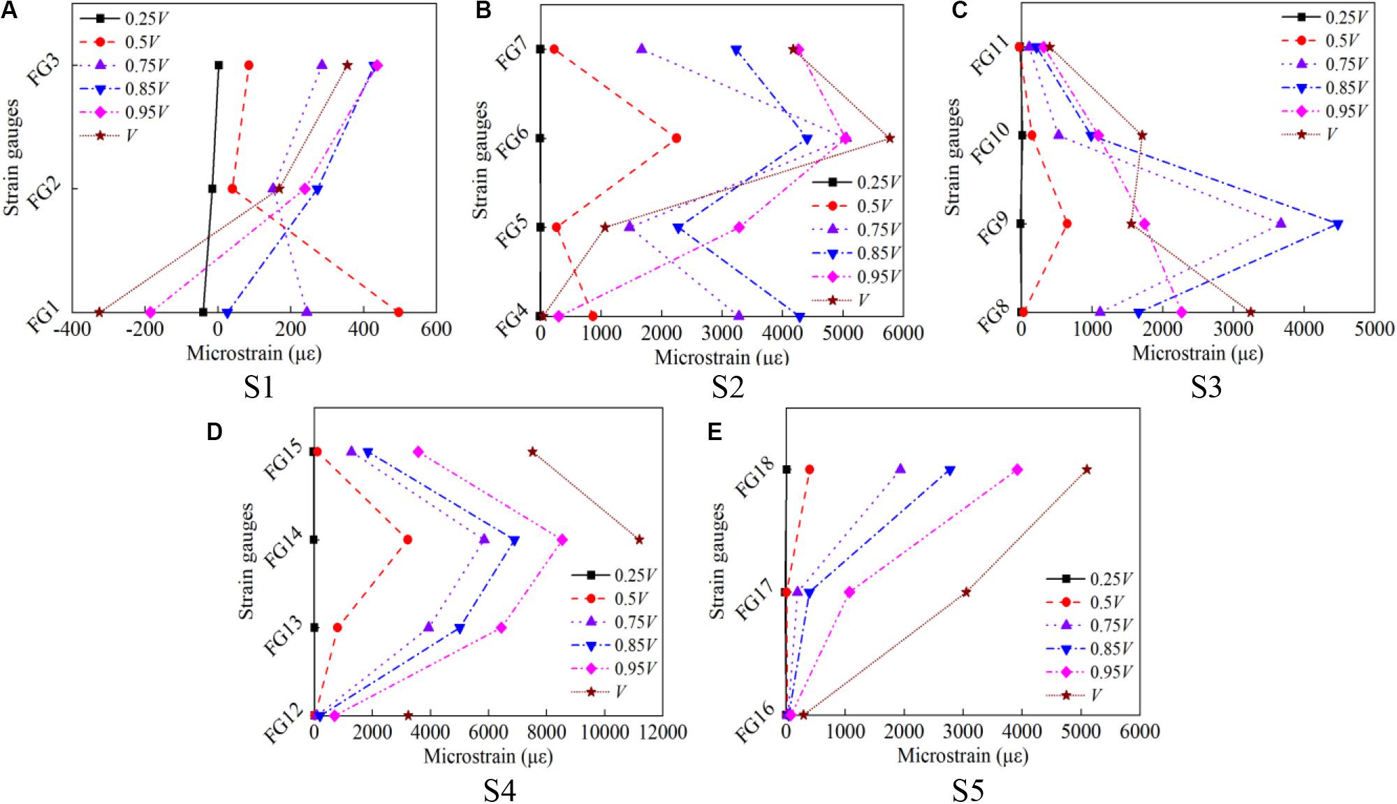
Figure 13. Strain distribution along the height of CFRP strips for HB-1-6. (A) S1, (B) S2, (C) S3, (D) S4, and (E) S5.
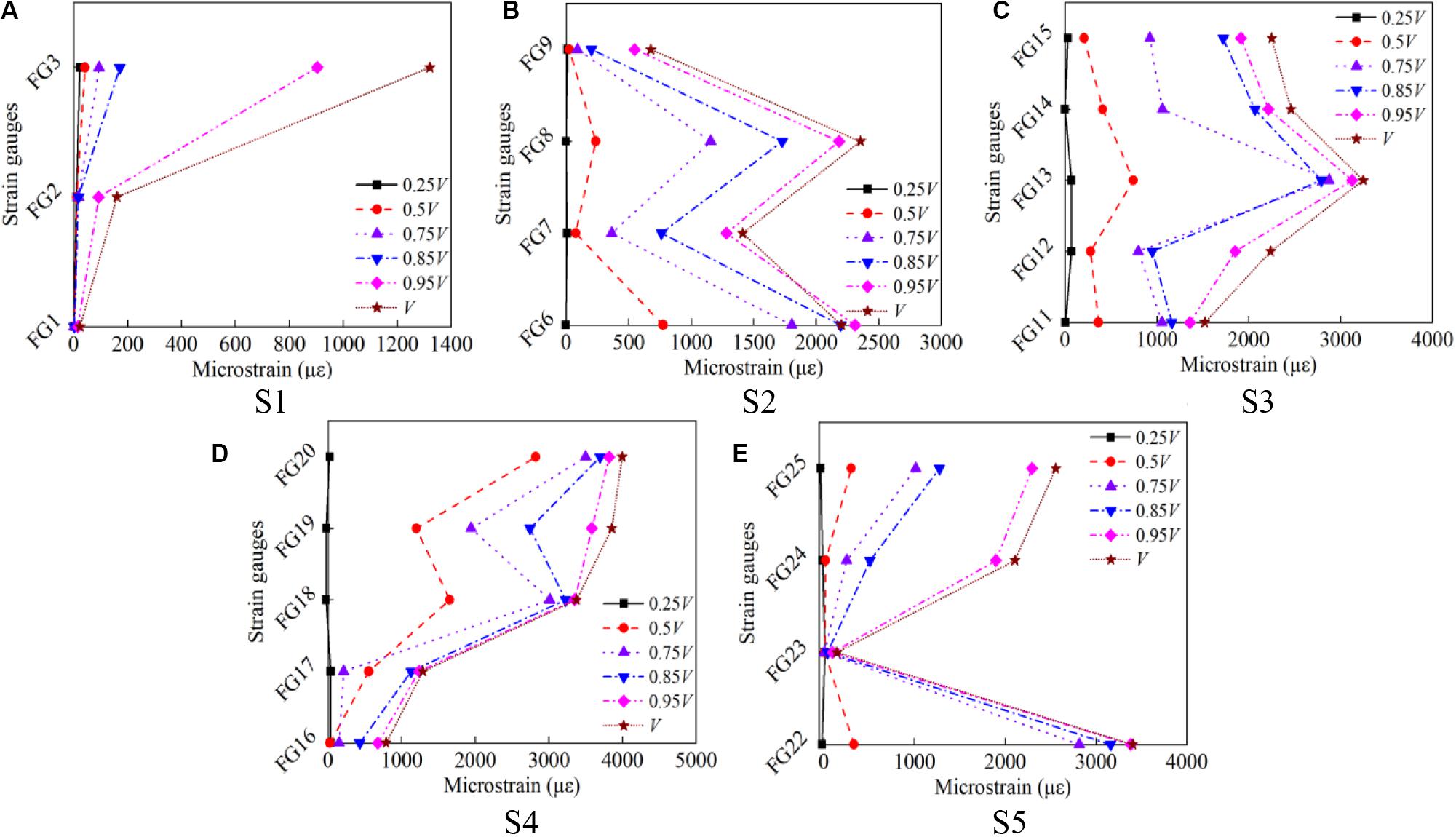
Figure 14. Strain distribution along the height of CFRP strips for EA-4-0. (A) S1. (B) S2. (C) S3. (D) S4, and (E) S5.
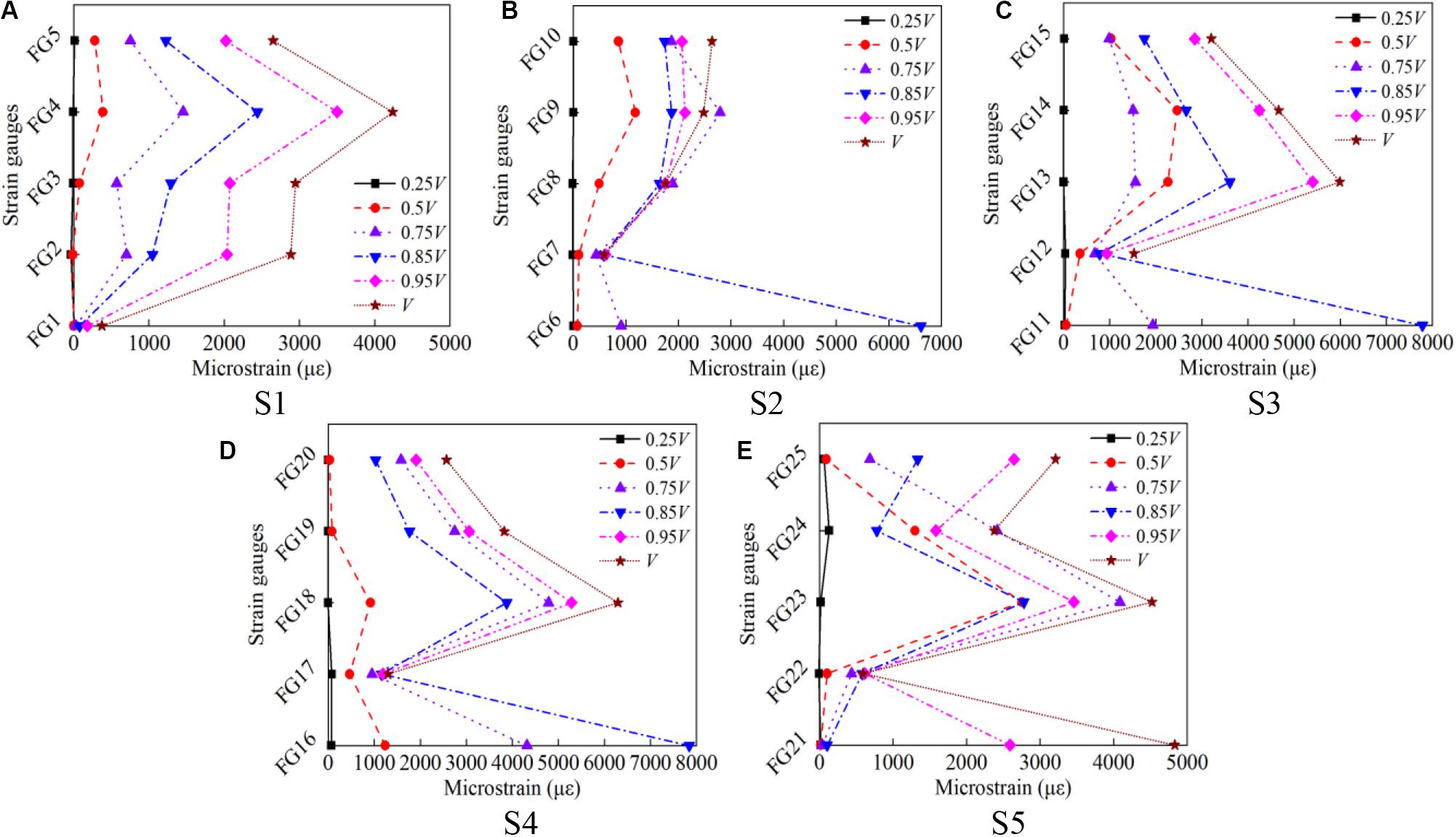
Figure 15. Strain distribution along the height of CFRP strips for EA-4-5. (A) S1, (B) S2, (C) S3, (D) S4, and (E) S5.
Discussion
Mechanism for Enhancing Deformability
Compared with the control specimen CB-0-0, the increases in deflection at the onset of shear strength increased by 9.2, 35.5, 35.3, and 43.9% for specimens under torque moments of 0, 3, 6, and 12 N ⋅ m, respectively. For the EA-CFRP shear-strengthening group, compared with the control specimen CB-0-0, the deflection at peak load showed increments of 12.6, 75.8, 80.5, 84.1, and 81.2% for beams with the width of deformation segments at 0, 5, 7.5, 12.5, and 15 mm, respectively. Clearly, the EA system was superior to the HB system in terms of enhancing member deformability.
The deformability enhancing mechanisms of these two anchorage devices were different. For the HB-CFRP system, the increment in deflection can be explained from two aspects. First, the additional bonding force provided by the capping steel plates enabled larger CFRP straining before debonding. As stated previously, the capping steel plates were bonded to the CFRP strips. Second, due to the normal pressure from the pre-applied torque moment, the CFRP strips were tightly fastened to the beam, which contributed to strong interfacial friction. The relative slip between the CFRP sheets and the concrete after debonding was possible due to the frictional forces, which helped enable a gradual debonding such that the beam did not fail. Thus, the beam experienced larger deformation before the force equilibrium in the vertical direction being broken due to the loss of frictional resistance where the CFRP strips could no longer resist any vertical force. It is believed that the second mechanism dominated the enhancement in deformability.
As for the H-type EA-CFRP system, the mechanism of increased deformability was due to the deformation segment, i.e., the ductile steel section, as shown in Figure 4B. Once the CFRP strips had debonded, the dual functions of the EA were activated, providing tensile force and undergoing large inelastic deformation to enable the beam to carry the increased applied load and experience larger deflection. Figure 16 uses specimen EA-4-5 as an example. It can clearly be observed that the strain of the deformation segment continually increased up to fracture. Almost all inelastic deformation of the anchor was concentrated in this part.
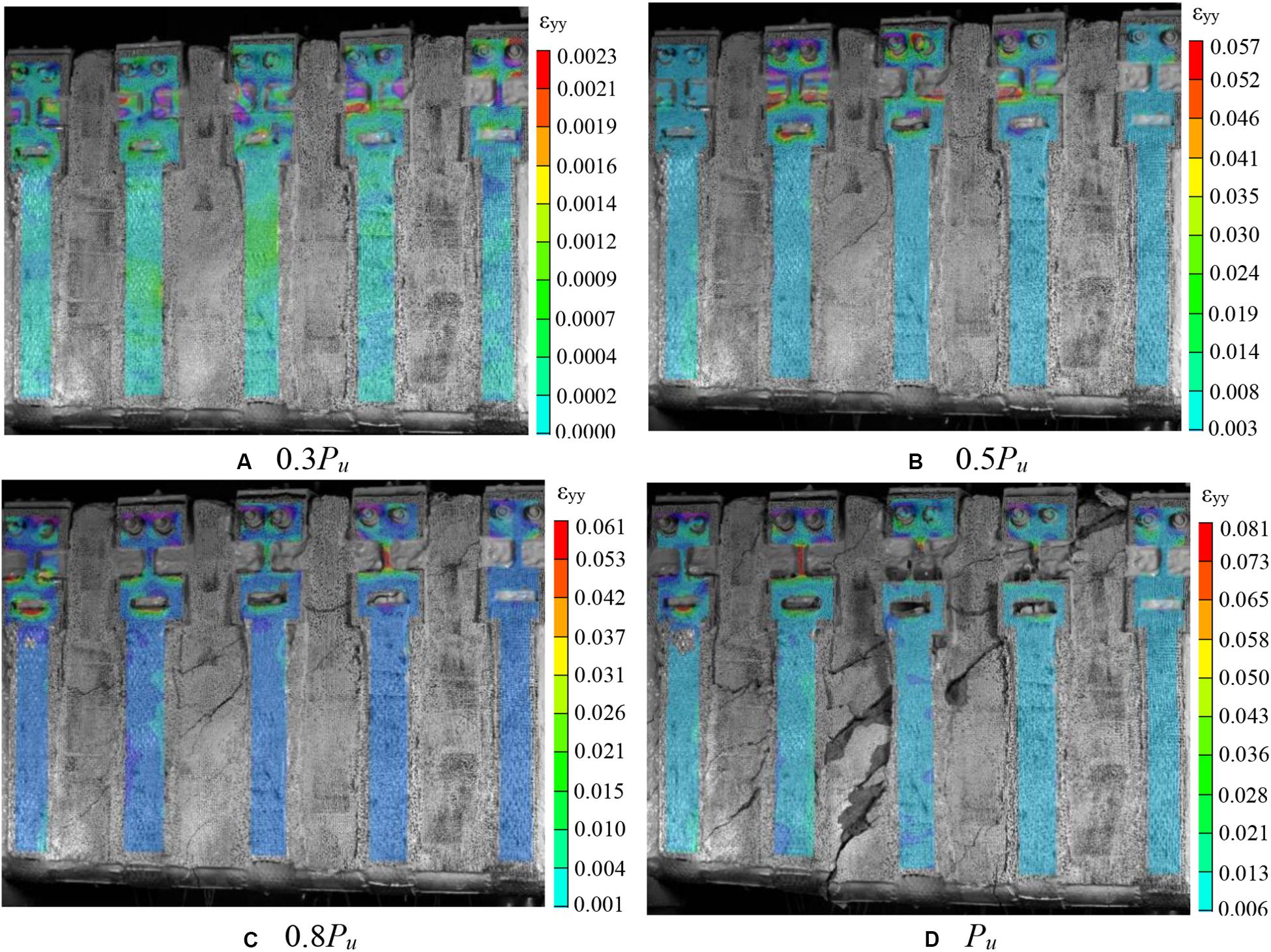
Figure 16. Strain distribution of H-type anchor for EA-4-5 measured by DIC. (A) 0.3Pu, (B) 0.5Pu, (C) 0.8Pu, and (D) Pu.
Components of Shear Strength and Their Interactions
Generally, the shear strength of a CFRP shear-strengthened RC beam comes from three components, the contributions of concrete (Vc), stirrup (Vs), and FRP (Vf), and can be expressed by Eq. (1) as per ACI 440 (2008). The value of Vf can be calculated by Eq. (2) (Zhou Y. W. et al., 2019):
where Vfi is the force in the i-th FRP strip, n is the number of FRP strips intersecting the CDC, Efrp is the elastic modulus of the FRP, tfrp is the total thickness of the FRP strips, wfrp is the width of the CFRP strip, and εfrp is the measured strain of an CFRP strip at a location intersecting the CDC. Furthermore, provided that the value of Vc + Vs for each specimen is equal that of the control beam (Chen et al., 2016; Li and Leung, 2017), the increased shear strength due to the incorporation of CFRP, Vg–FRP, is equal to V – (Vc + Vs)CB–0–0. Vc–s–f is defined as the interaction or indirect contribution of the CFRP and is calculated by Vg–FRP – Vf.
The values of shear strength components and their possible interactions are summarized in Table 4. For the HB-CFRP system, Vf for EB-1-0 was 38.5 kN, larger than those for HB-1-3 (30.2 kN) and HB-1-6 (33.4 kN) under a small or moderate anchoring effect. This is simply because a certain extent of strain snap-back occurred in HB-1-3 and HB-1-6 before reaching peak load, which was different from the case of EB-1-0, which reached the maximum capacity as soon as CFRP debonding occurred. As expected, the post-snap-back average residual strain in the CFRP strips increased with the torque moment applied, as indicated by the increased Vf values, due to the more profound frictional effect between the debonded CFRP and concrete interfaces. Concerning the H-type EA system, Vf increased proportionally with the axial stiffness (width) of the deformation segment of the anchoring steel plate. The wider deformation section could provide a larger tensile force to enable the CFRP strips to undergo a larger strain, which contributed to a larger value of Vf.
The interactions between the CFRP and concrete as well as the stirrups are summarized in Table 4. Vf is the direct shear contribution of the CFRP, calculated per Eq. (2). Vg–FRP is the indirect contribution of CFRP, defined as the shear strength of the CFRP shear-strengthened beam minus the shear strength of the control beam, i.e., V – (Vc + Vs)CB–0–0. The interaction (Vc–s–f) between Vf and Vc plus Vs is defined as: Vg–FRP – Vf. As shown in Table 4, the value of Vg–FRP was normally larger than that of Vf except for specimens EB-4-0 and EA-4-15, indicating a positive interaction between Vf and Vc plus Vs. For the HB-CFRP group, Vc–s–f increased from 11.6 kN for the EB-CFRP beam without an anchor to 53.9, 57.9, and 69.3 kN for beams under torque moments of 3, 6, and 12 N ⋅ m, respectively, indicating that Vc plus Vs was significantly enhanced by the HB anchoring system. For the H-type EB-CFRP group, the Vc–s–f of specimens EB-4-0 and EB-4-15 were -12.7 kN and -18 kN, respectively, indicating that the inclusion of CFRP shear strengthening adversely affected the value of Vc plus Vs. This adverse shear interaction could be due to the weakened shear transfer mechanisms, e.g., aggregate interlock, dowel action, and shear transferred in compression-zone concrete (Chen et al., 2016), because of the larger crack width and larger deflection compared with the control beam. These reasons are qualitative, due to the limited measurement techniques. More accurate measurements of Vs and Vc (Wu and Hu, 2017; Hu and Wu, 2018) are needed to further clarify the reason behind the interaction of the shear contributions. Similar adverse shear interactions between Vf and Vc plus Vs were reported by Pellegrino and Modena (2002, 2006), Bousselham and Chaallal (2004); Teng et al. (2009), Jirawattanasomkul et al. (2013), and Chen et al. (2016). For specimens EA-4-5, EA-4-7.5 and EA-4-12.5, the shear interactions were positive at 33.2, 21.2, and 43.8 kN, generally smaller than that of the HB-CFRP- strengthened group. This could be because of the degraded shear transfer actions (e.g., aggregate interlock, dowel action, and shear transferred in the compression-zone concrete) owing to a much larger deflection and more severe cracking experienced by specimens in the H-type EA-CFRP retrofitting group. The positive shear interaction (e.g., Vc–s–f) in the HB-CFRP system was more prominent than in the H-type EA system.
Conclusion
This paper investigated the effects of two CFRP shear-strengthening systems on the shear performance of retrofitted RC beams. One was an HB system with the CFRP strips anchored by mechanical fasteners, where torque moment was applied to increase the frictional forces at the interface of the CFRP and concrete. The other was the so-called H-type EA system with a ductile deformation segment. Ten beam specimens were tested, and key results were presented, analyzed, and discussed in terms of the failure mode, load-deflection response, critical loads, angle of CDC, strain distribution and development in the CFRP strips, FRP shear contribution, and shear interactions. The main conclusions are as follows:
1. Both the HB-CFRP and the EA-CFRP strengthening systems can significantly improve the shear strength and deformability of the retrofitted RC beams.
2. The enhanced shear strength and deformability of the HB-CFRP group was caused by the increased CFRP utilization or positive shear interaction as well as the gradual debonding process, and the enhancement was proportional to the pre-applied torque moment. For the EA-CFRP group, the ductile H-type EA contributed to enhancing shear capacity and deformability, and this enhancement increased with the width of the deformation section, up to 12.5 mm.
3. The H-type EA is much more effective than the HB method in terms of enhancing ductility. Compared with that of the control beam, the maximum increments of deflections of the H-type EA-CFRP- and HB-CFRP-strengthened beams at the onset of shear strength were 84.1 and 43.9%, respectively.
4. Compared with the control member, for beams retrofitted by HB-CFRP and EA-CFRP systems, the increments in shear capacity reached up to 54.6 and 68.5%, respectively,
5. For the HB-CFRP system, the failure mode can be changed from debonding to CFRP rupture by increasing the applied torque moment (e.g., HB-1-12). For the H-type EA system, the small width of the deformation section may lead to fracturing of the deformation section (e.g., SEB-4-5).
6. The CDC inclination of all specimens was less than 45°, ranging from 38° to 44°, which is the value (45°) recommended in typical design guidelines (e.g., Japan Society of Civil Engineers [JSCE], 2001; American Concrete Institute [ACI], 2008; Technical Report 55 [TR 55], 2012).
7. Both positive and negative shear interactions were observed between Vf and Vc plus Vs. The Vc–s–f to V ratios can be as large as 21.3 and 12.3% in the HB-CFRP system and H-type EA-CFRP system, respectively. More accurate measurements of Vc and Vs are needed to further clarify the interactions between Vf and Vc, and Vf and Vs.
Data Availability Statement
All datasets presented in this study are included in the article/supplementary material.
Author Contributions
ZH: investigation, visualization, formal analysis, and writing-original draft. XZ: validation, resources, and supervision. MG: methodology. XH: validation. BH: conceptualization, supervision, methodology, writing-original draft, and writing-review and editing. All authors contributed to the article and approved the submitted version.
Conflict of Interest
The authors declare that the research was conducted in the absence of any commercial or financial relationships that could be construed as a potential conflict of interest.
Acknowledgments
This work described in this manuscript was financially supported by the National Key Research & Development Plan of China (No. 2018YFE0125000) and the National Natural Science Foundation of China (Grants Nos. 51978412 and 51878414), to which the authors are grateful. Postgraduate students Xilong Chen and Xiaowei Wang took part in the tests, and their contributions to the work are acknowledged.
References
ACI-ASCE Committee 326 (1962). Shear and diagonal tension. ACI J. Proc. 59, 277–334. doi: 10.14359/7920
American Concrete Institute [ACI] (2008). Guide for the Design and Construction of Externally Bonded FRP Systems for Strengthening Concrete Structures. Farmington Hills, MI: American Concrete Institute.
American society for testing and materials [ASTM] (2004). Standard Test Method for Tensile Properties of Polymer Matrix Composite Materials. West Conshohocken, PA: ASTM.
American society for testing and materials [ASTM] (2005). Standard Test Method for Compressive Strength of Cylindrical Concrete Specimens. West Conshohocken, PA: ASTM.
American society for testing and materials [ASTM] (2012). Standard test Methods and Definitions for Mechanical Testing of Steel Products. West Conshohocken, PA: ASTM.
Bae, S. W., and Belarbi, A. (2013). Behavior of various anchorage systems used for shear strengthening of concrete structures with externally bonded FRP sheets. J. Bridge Eng. 18, 837–847. doi: 10.1061/(asce)be.1943-5592.0000420
Bank, L. (2004). “Mechanically fastened FRP (MF-FRP)-A viable alternative for strengthening RC members,” in Proceedings of the FRP Composites in Civil Engineering (CICE 2004), Adelaide, SA, doi: 10.1201/9780203970850.ch1
Bousselham, A., and Chaallal, O. (2004). Shear strengthening reinforced concrete beams with fiber-reinforced polymer: assessment of influencing parameters and required research. ACI Struct. J. 101, 219–227. doi: 10.14359/13019
Bousselham, A., and Chaallal, O. (2006). Effect of transverse steel and shear span on the performance of RC beams strengthened in shear with CFRP. Compos. Part B Eng. 37, 37–46. doi: 10.1016/j.compositesb.2005.05.012
Cao, Y. G., Wu, Y. F., and Jiang, C. (2018). Stress-strain relationship of FRP confined concrete columns under combined axial load and bending moment. Compos. Part B 134, 207–217. doi: 10.1016/j.compositesb.2017.09.063
Chaallal, O., Nollet, M. J., and Perraton, D. (1998). Shear strengthening of RC beams by externally bonded side CFRP strips. J. Compos. Constr. 2, 111–113. doi: 10.1061/(asce)1090-0268(1998)2:2(111)
Chen, C., Cheng, L., Sui, L., Xing, F., Li, D., and Zhou, Y. W. (2018a). Design method of end anchored FRP strengthened concrete structures. Eng. Struct. 176, 143–158. doi: 10.1016/j.engstruct.2018.08.081
Chen, C., Sui, L. L., Xing, F., Li, D. W., Zhou, Y. W., and Li, P. D. (2018b). Predicting bond behavior of HB FRP strengthened concrete structures subjected to different confining effects. Compos. Struct. 187, 212–225. doi: 10.1016/j.compstruct.2017.12.036
Chen, G. M., Teng, J. G., Chen, J. F., and Rosenboom, O. A. (2010). Interaction between steel stirrups and shear-strengthening FRP strips in RC beams. J. Compos. Constr. 14, 498–509. doi: 10.1061/(asce)cc.1943-5614.0000120
Chen, G. M., Zhang, Z., Li, Y. L., Li, X. Q., and Zhou, C. Y. (2016). T-section RC beams shear-strengthened with anchored CFRP U-strips. Compos. Struct. 144, 57–79. doi: 10.1016/j.compstruct.2016.02.033
Chen, J. F., and Teng, J. G. (2001). Anchorage strength models for FRP and steel plates bonded to concrete. J. Struct. Eng. 127, 784–791. doi: 10.1061/(asce)0733-9445(2001)127:7(784)
Chen, J. F., and Teng, J. G. (2003a). Shear capacity of FRP-strengthened RC beams: FRP debonding. Constr. Build. Mater. 17, 27–41. doi: 10.1016/s0950-0618(02)00091-0
Chen, J. F., and Teng, J. G. (2003b). Shear capacity of fiber-reinforced polymer-strengthened reinforced concrete beams: fiber reinforced polymer rupture. J. Struct. Eng. 129, 615–625. doi: 10.1061/(asce)0733-9445(2003)129:5(615)
Clarke, J. L. (2000). The Use of Fiber Composites in Concrete Bridges—a State of the Art Review. London: Concrete Bridge Development Group.
Colalillo, M. A., and Sheikh, S. A. (2014). Behavior of shear-critical reinforced concrete beams strengthened with fiber-reinforced polymer-experimentation. ACI Struct. J. 111, 1373–1384. doi: 10.14359/51687035
De Lorenzis, L., and Nanni, A. (2002). Bond between near-surface mounted fiber-reinforced polymer rods and concrete in structural strengthening. ACI Struct. J. 99, 123–132. doi: 10.14359/11534
Deniaud, C., and Cheng, J. J. R. (2003). Reinforced concrete T-beams strengthened in shear with fiber reinforced polymer sheets. J. Compos. Constr. 7, 302–310. doi: 10.1061/(asce)1090-0268(2003)7:4(302)
Fico, R., Prota, A., and Manfredi, G. (2008). Assessment of Eurocode-like design equations for the shear capacity of FRP RC members. Compos. Part B Eng. 39, 792–805. doi: 10.1016/j.compositesb.2007.10.007
Hu, B., and Wu, Y. F. (2017). Quantification of shear cracking in reinforced concrete beams. Eng. Struct. 147, 666–678. doi: 10.1016/j.engstruct.2017.06.035
Hu, B., and Wu, Y. F. (2018). Effect of shear span-to-depth ratio on shear strength components of RC beams. Eng. Struct. 168, 770–783. doi: 10.1016/j.engstruct.2018.05.017
Hu, B., Zhou, Y. W., Xing, F., Sui, L. L., and Luo, M. S. (2019). Experimental and theoretical investigation on the hybrid CFRP-ECC flexural strengthening of RC beams with corroded longitudinal reinforcement. Eng. Struct. 200:109717. doi: 10.1016/j.engstruct.2019.109717
Japan Society of Civil Engineers [JSCE] (2001). Recommendations for Upgrading of Concrete Structures with use of Continuous Fiber Sheets. Tokyo: JSCE.
Jirawattanasomkul, T., Dai, J. G., Zhang, D. W., Senda, M., and Ueda, T. (2013). Experimental study on shear behavior of reinforced-concrete members fully wrapped with large rupture strain FRP composites. J. Compos. Constr. 18:4013009. doi: 10.1061/(ASCE)CC.1943-5614.0000442
Kalfat, R., Al-Mahaidi, R., and Smith, S. T. (2013). Anchorage devices used to improve the performance of reinforced concrete beams retrofitted with FRP composites: state-of-the-art review. J. Compos. Constr. 17, 14–33. doi: 10.1061/(asce)cc.1943-5614.0000276
Karayannis, C. G., and Golias, E. (2018). Full scale tests of RC joints with minor to moderate seismic damage repaired using C-FRP sheets. Earthq. Struct. 15, 617–627. doi: 10.12989/eas.2018.15.6.617
Karayannis, C. G., and Sirkelis, G. M. (2008). Strengthening and rehabilitation of RC beam-column joints using carbon-FRP jacketing and epoxy resin injection. Earthq. Eng. Struct. Dynam. 37, 769–790. doi: 10.1002/eqe.785
Khalifa, A., and Nanni, A. (2000). Improving shear capacity of existing RC T-section beams using CFRP composites. Cement. Concr. Compos. 22, 165–174. doi: 10.1016/S0958-9465(99)00051-7
Li, W., and Leung, C. K. Y. (2017). Effect of shear span-depth ratio on mechanical performance of RC beams strengthened in shear with U-wrapping FRP strips. Compos. Struct. 20, 141–157. doi: 10.1061/(ASCE)CC.1943-5614.0000627
Mari, A., Cladera, A., Oller, E., and Bairan, J. (2014). Shear design of FRP reinforced concrete beams without transverse reinforcement. Compos. Part B Eng. 57, 228–241. doi: 10.1016/j.compositesb.2013.10.005
Ministry of Housing and Urban-Rural Development Republic of China [MOHURD] (2010). “Code for design of concrete structures,” in MOHURD (Ministry of Housing and Urban-Rural Development Republic of China) GB 50010-2010 (Beijing, China: China Architecture & Building Press).
Mofidi, A., and Chaallal, O. (2011). Shear strengthening of RC beams with EB-FRP: influencing factors and conceptual debonding model. J. Compos. Constr. 15, 62–74. doi: 10.1061/(ASCE)CC.1943-5614.0000153
Mofidi, A., Chaallal, O., Benmokrane, B., and Neale, K. (2012). Performance of end-anchorage systems for RC beams strengthened in shear with epoxy-bonded FRP. J. Compos. Constr. 16, 322–331. doi: 10.1061/(asce)cc.1943-5614.0000263
National Research Council [CNR] (2013). Guide for the Design and Construction of Externally Bonded FRP Systems for Strengthening Existing Structures. Rome: CNR.
Neale, K. W. (2000). FRPs for structural rehabilitation: a survey of recent progress. Prog. Struct. Eng. Mater. 2, 133–138. doi: 10.1002/1528-2716(200004/06)2:2<133::aid-pse16>3.0.co;2-c
Pellegrino, C., and Modena, C. (2002). Fiber reinforced polymer shear strengthening of reinforced concrete beams with transverse steel reinforcement. J. Compos. Constr. 6, 104–111. doi: 10.1061/(asce)1090-0268(2002)6:2(104)
Pellegrino, C., and Modena, C. (2006). Fiber-reinforced polymer shear strengthening of reinforced concrete beams: experimental study and analytical modeling. ACI Struct. J. 103, 720–728. doi: 10.14359/16924
Perera, R., Barchín, M., Arteaga, A., and Diego, A. D. (2010). Prediction of the ultimate strength of reinforced concrete beams FRP-strengthened in shear using neural networks. Compos. Part B Eng. 41, 287–298. doi: 10.1016/j.compositesb.2010.03.003
Rousakis, T. C., Karabinis, A. I., Kiousis, P. D., and Tepfers, R. (2008). Analytical modelling of plastic behaviour of uniformly FRP confined concrete members. Compos. Part B Eng. 39, 1104–1113. doi: 10.1016/j.compositesb.2008.05.001
Rousakis, T. C., Saridaki, M. E., Mavrothalassitou, S. A., and Hui, D. (2016). Utilization of hybrid approach towards advanced database of concrete beams strengthened in shear with FRPs. Compos. Part B Eng. 85, 315–335. doi: 10.1016/j.compositesb.2015.09.031
Smith, S. T., Hu, S., Kim, S. J., and Seracino, R. (2011). FRP-strengthened RC slabs anchored with FRP anchors. Eng. Struct. 33, 1075–1087. doi: 10.1016/j.engstruct.2010.11.018
Technical Report 55 [TR 55] (2012). Design Guidance for Strengthening Concrete Structures Using Fiber Composite Materials. TR55, 3rd Edn. London: The Concrete Society.
Teng, J. G., Chen, G. M., Chen, J. F., Rosenboom, O. A., and Lam, L. (2009). Behavior of RC beams shear strengthened with bonded or unbonded FRP Wraps. J. Compos. Constr. 13, 394–404. doi: 10.1061/(asce)cc.1943-5614.0000040
Teng, J. G., Chen, J. F., Smith, S. T., and Lam, L. (2002). FRP-Strengthened RC Structures. Hoboken, NJ: John Wiley and Sons, Inc.
Teng, J. G., Chen, J. F., Smith, S. T., and Lam, L. (2003). Behavior and strength of FRP-strengthened RC structures: a state-of-the-art review. Struct. Build. 156, 51–62. doi: 10.1680/stbu.2003.156.1.51
Vecchio, F. J., and Collins, M. P. (1986). The modified compression fired theory for reinforced concrete elements subjected to shear. ACI J. 83, 219–231. doi: 10.14359/10416
Wu, Y. F., and Hu, B. (2017). Shear strength components in reinforced concrete members. J. Strut. Eng. 143:04017092. doi: 10.1061/(asce)st.1943-541x.0001832
Wu, Y. F., and Huang, Y. (2008). Hybrid bonding of FRP to reinforced concrete structures. J. Compos. Constr. 12, 266–273. doi: 10.1061/(asce)1090-0268(2008)12:3(266)
Wu, Y. F., Wang, Z., Liu, K., and He, W. (2009). Numerical Analyses of Hybrid-Bonded FRP Strengthened Concrete Beams. Comp. Aided Civil Infrastruct. Eng. 24, 371–384. doi: 10.1111/j.1467-8667.2009.00596.x
Wu, Y. F., Yan, J. H., Zhou, Y. W., and Xiao, Y. (2010). Ultimate strength of reinforced concrete beams retrofitted with hybrid bonded fiber-reinforced polymer. ACI Struct. J. 107, 451–460. doi: 10.14359/51663818
Zhai, K. J., Fang, H. Y., Fu, B., Wang, F. M., and Hu, B. Y. (2020). Mechanical response of externally bonded CFRP on repair of PC with broken wires under internal water pressure. Constr. Build. Mater. 239:117878. doi: 10.1016/j.conbuildmat.2019.117878
Zhou, A., Qin, R., Chow, C. L., and Lau, D. (2019). Structural performance of FRP confined seawater concrete columns under chloride environment. Compos. Struct. 216, 12–19. doi: 10.1016/j.compstruct.2019.02.058
Zhou, Y. W., Guo, M. H., Sui, L. L., Xing, F., Hu, B., Huang, Z. Y., et al. (2019). Shear strength components of adjustable hybrid bonded CFRP shear strengthened RC beams. Compos. Part B Eng. 163, 36–51. doi: 10.1016/j.compositesb.2018.11.020
Zhou, Y. W., Chen, X., Wang, X. H., Sui, L. L., Huang, X. X., Guo, M. H., et al. (2020). Seismic performance of large rupture strain FRP retrofitted RC columns with corroded steel reinforcement. Eng. Struct. 216:110744. doi: 10.1016/j.engstruct.2020.110744
Zhou, Y. W., Chen, X. L., Fan, Z. H., Sui, L. L., Li, D. W., and Xing, F. (2017). Bond behaviors of FRP-to-concrete interface under the control of a novel end-anchorage system. Compos. Struct. 168, 130–142. doi: 10.1016/j.compstruct.2017.02.056
Keywords: shear strengthening, ductile anchoring system, CFRP, ductility, test
Citation: Hu Z, Zhou X, Guo M, Huang X and Hu B (2020) Enhancing the Performance of CFRP Shear-Strengthened RC Beams Using “Ductile” Anchoring Devices. Front. Mater. 7:292. doi: 10.3389/fmats.2020.00292
Received: 30 May 2020; Accepted: 03 August 2020;
Published: 02 October 2020.
Edited by:
Baolin Wan, Marquette University, United StatesReviewed by:
M. Iqbal Khan, King Saud University, Saudi ArabiaJiafei Jiang, Tongji University, China
Copyright © 2020 Hu, Zhou, Guo, Huang and Hu. This is an open-access article distributed under the terms of the Creative Commons Attribution License (CC BY). The use, distribution or reproduction in other forums is permitted, provided the original author(s) and the copyright owner(s) are credited and that the original publication in this journal is cited, in accordance with accepted academic practice. No use, distribution or reproduction is permitted which does not comply with these terms.
*Correspondence: Biao Hu, Ymlhb2h1My1jQHN6dS5lZHUuY24=