 Shuai Fang
- School of Civil Engineering and Transportation, South China University of Technology, Guangzhou, China
Chloride-induced corrosion of reinforcement has endangered the safety of reinforced concrete (RC) structures. It is, therefore, necessary to strengthen the corroded RC members to ensure structural safety. This study aims to investigate the effectiveness of alkali-activated slag (AAS) ferrocement jackets in strengthening corroded RC columns. AAS ferrocement specimens with various layers of stainless steel wire mesh (SSWM) were subjected to direct tensile tests. Square RC columns suffered artificially accelerated corrosion and were subsequently strengthened by AAS ferrocement jackets. Axial compressive tests were conducted on the column specimens. Experimental results have shown that corroded specimens suffer severe losses in loading capacity up to 46% as compared with the control one. Volume fraction of transverse SSWM (ρv) plays primary role in loading capacity and ductility of ferrocement and its confinement on column specimens. Ferrocement with ρv of 0.266% can rehabilitate loading capacity of specimens with corrosion degrees of 8.9% and 18.3% by 37% and 46%, respectively. Corroded specimen strengthened by ferrocement with ρv of 0.532% achieves approximately two times the ductility than the one without strengthening. Ferrocement jackets provide better and uniform confinement to core concrete than new stirrups. Analytical models are proposed to predict tensile strength of AAS ferrocement and loading capacity of specimens strengthened by ferrocement jackets. The prediction is in good agreement with experimental results.
Introduction
Corrosion of reinforcements has become a primary cause of degradation of RC structures in corrosive environments (Roberge, 1999). It has led to serious structural problems, such as reduction of cross-sectional area of reinforcements and deteriorative bond between concrete and reinforcements. Due to large increases in the volume of rust, tensile stress is introduced and results in cracks and spalling of concrete cover. The corrosion of reinforcements weakens loading capacity and ductility of members and threatens safety of RC structures (Meda et al., 2014). It is necessary to develop effective and economic strengthening methods to rehabilitate loading capacity and extend service life of structures.
In recent years, various materials and techniques, such as concrete jacketing, steel jacketing, fiber-reinforced polymer (FRP) wrapping, and ferrocement, have been proposed for strengthening the corroded structures. Concrete jacketing is an effective strengthening method at low cost. It increases cross-sectional area and provides extra loading capacity for concrete members (Li et al., 2009; Liu, 2009; Meda et al., 2016). However, this method reduces usable area of buildings and is time-consuming in construction. As compared with concrete, steel has the advantages of high strength, thin thickness, and easy and rapid installation, and thus are extensively used. Peng et al. (2015) and Li et al. (2013) strengthened corroded RC beams by bolting and bonding steel plates with thickness of 3–5 mm, respectively. The strengthening effectively improved loading capacity and ductility, and reduced mid-span deflection of beams. This strengthening method, however, does not consider durability of steel jackets in chloride-contaminated environment. FRP is waterproof and chemically inert to chloride aggression, which guarantees durability of strengthened structures (Lee et al., 2000; Kashi et al., 2017). FRP strengthening is generally achieved by wrapping columns or bonding the tensile region of beams and slabs. It can significantly enhance loading capacity and seismic performance of corroded members (Tastani and Pantazopoulou, 2004; Triantafyllou et al., 2017). Al-Saidy et al. (2010) and Haddad (2016) strengthened simply supported corroded beams by bonding FRP sheets on the bottom of beams. Bending capacity and stiffness of beams increased with increasing layers of FRP. FRP can also increase compressive strength and ductility of corroded RC columns by lateral confinement, without a change in axial stiffness (Pantazopoulouet al., 2001; Joshi et al., 2015). However, FRP rapidly loses its strength at moderate temperature because resin matrix is transformed into viscous flow state at temperatures from 60 to 80°C (ACI Committee 440, 2002). Mechanical contribution of FRP jackets should be ignored when FRP-confined columns are subjected to fire (Han et al., 2006). Poor fire resistance of FRP limits its application in buildings. As an alternative, ferrocement has great potentiality in strengthening structures. Ferrocement is a thin cementitious composite reinforced by layers of meshes with small diameter (ACI Committee 549, 1997). Benefited by the protection of cement cover, ferrocement performs well in fire and corrosive environment. Meshes in ferrocement contribute to restrain cracks and improve tensile strength and ductility. Jayasree et al. (2016) investigated the effect of ferrocement jackets on the flexural behavior of corroded RC beams. Ferrocement with a mesh fraction of 1.2% by volume can increase bending capacity by 39% in beams with a corrosion degree of 10%. The strengthened beams even achieved higher ultimate load and stiffness than uncorroded ones. Kondraivendhan and Pradhan (2009) investigated the confinement of ferrocement on cylindrical concrete specimens. Ferrocement efficiently enhanced compressive strength, as well as axial and radial strain of concrete specimens. The lower the compressive strength of core concrete was, the higher enhancement the ferrocement resulted in.
Traditional ferrocement adopts Portland cement as the substrate material. However, cement consumes much fossil fuel and releases a large amount of greenhouse gas into the atmosphere during manufacture. One ton of carbon dioxide is emitted for each ton of cement produced (Roy, 1999). By contrast, AAS is an environmentally friendly material with lower energy consumption. It uses blast furnace slag, an industrial waste of iron production, as the raw material and can develop strength that is comparable to Portland cement. AAS mortar can achieve a compressive strength of 82.9 and 94.5 MPa at 7 and 28 days, respectively (Fang et al., 2020). Besides high strength, AAS exhibits outstanding resistance to chemical attack and protection to reinforcements. Shi (2003) tested corroded depth of AAS paste immersed in nitric acid and acetic acid with a pH value of 3.0. Test results showed that AAS specimens corroded more slowly than the cement ones in the acid solution. Pu (2010) accelerated corrosion of steel bars embedded in concrete using drying–wetting cycle. The corrosion-induced mass loss of bars was 0.18% in AAS concrete after 75 cycles, whereas that increased to 1.9% in cement concrete after only 45 cycles.
With advantages of excellent mechanical behavior, durability, and environment-friendliness, AAS-based ferrocement has exhibited its tremendous potential in strengthening corroded RC columns in previous studies. The strengthened columns obtained significant rehabilitation in both loading capacity and ductility under various levels of eccentricity (Fang et al., 2017). This study turns to focus on the influence of AAS ferrocement jackets in axial compressive performance of corroded RC columns. For this objective, direct tensile tests were conducted to estimate tensile performance of AAS ferrocement. RC column specimens were subjected to artificially accelerated corrosion and subsequently strengthened by wrapping core concrete with AAS ferrocement jackets. Axial compressive tests were conducted on control, corroded, and strengthened specimens. Test results were used to assess corrosion-induced damage and effectiveness of proposed strengthening method.
Materials and Experiments
Direct Tensile Test on AAS Ferrocement
In this study, AAS ferrocement jackets were used to enhance compressive performance of corroded columns by their confinement to core concrete. To quantify the confinement, tensile performance of AAS ferrocement with various layers of SSWM was evaluated in this section. AAS with alkali content of 3% of slag mass, modulus of 0.95, sand slag ratio of 2.0, and water slag ratio of 0.44 was adopted as the substrate material for mortar and ferrocement specimens. SSWM with a grid size of 8.5 mm and a wire diameter of 1.0 mm was adopted as the reinforcement. Five groups of specimens, including mesh, mortar, and ferrocement with one, two, and four layers of SSWM, were prepared. There were three specimens in each group. Dimensions of the specimens are shown in Figure 1. The specimens had a cross-section of 30 mm × 12.7 mm in the middle and enlarged cross-sections at both ends. For mesh specimens, one layer of SSWM was embedded in AAS mortar at each end to facilitate clamping the SSWM in fixture.
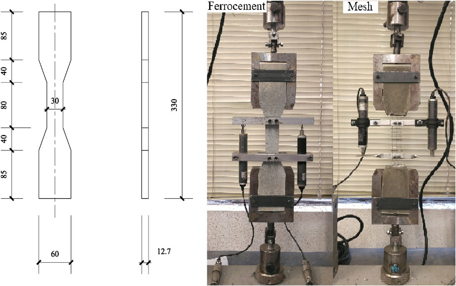
FIGURE 1. Schematic view of ferrocement specimen and tensile test (unit: mm).
The specimens were cured in water for 28 days and then subjected to direct tensile test. Axial load was applied through the fixtures attached to the enlarged ends of specimens. The ends of fixtures were connected to ball joints to avoid eccentricity. Loading rate of tensile test was 1.0 mm/min. Axial deformation was measured by a pair of aluminum fixtures with a gauge length of 80 mm. Relative displacement between the fixtures was recorded by a pair of linear variable differential transformers, as shown in Figure 1.
Preparation of Column Specimens
Ten RC column specimens including one control specimen, four corroded ones, and five strengthened ones were prepared (Table 1). The specimens had a height of 900 mm and a cross-section of 200 mm × 200 mm. Concrete cover to main reinforcement was 38 mm. Deformed bars with a diameter of 12 mm (T12) and plain bars with a diameter of 6 mm (R6) were used as main reinforcements and stirrups, respectively. Measured yield strength of T12 and R6 bars was 550 and 477 MPa, respectively. Spacing of stirrups was 150 mm at mid-height of specimen. Stirrups were intensified at both ends of specimens to prevent failure at the end sections. The main reinforcements and stirrups were protected by epoxy at both ends of corroded and strengthened specimens (Figure 2). The specimens were cast horizontally and cured in water for 28 days. Compressive strengths of concrete (fcu) were tested when the column specimens were tested.
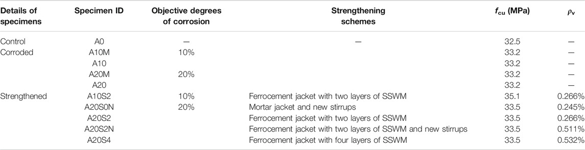
TABLE 1. Details of column specimens.
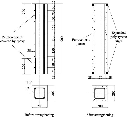
FIGURE 2. Schematic view of column specimen (unit: mm).
Artificially Accelerated Corrosion on Column Specimens
Once cured, nine specimens except the control specimen were subjected to artificially accelerated corrosion. Objective degrees of corrosion, i.e., corrosion-induced mass loss of main reinforcements, were 10% and 20% (Table 1). The column specimens were immersed in sodium chloride solution with a concentration of 5%. Air was pumped into the solution to supply oxygen to corrosion reaction. Main reinforcements and sodium chloride solution were connected to the anode and cathode of direct current power supply, respectively. The electric current of 0.68 A was kept constant throughout the test. According to Faraday’s law, this corrosion scheme could achieve mass loss in reinforcement with a rate of 0.476% per day, and total losses of 10% and 20% with test periods of 21 and 42 days, respectively. The actual mass loss was verified after the accelerated corrosion test.
Strengthening Schemes
Four different strengthening schemes, named S0N, S2, S2N, and S4, were used. S0, S2, and S4 represent AAS mortar jacket, and AAS ferrocement jacket with two and four layers of SSWM, respectively. N represents replacement of corroded stirrups by new ones. The volume fractions ρv of transverse strengthening reinforcements in schemes S0N, S2, S2N, and S4, i.e., the volume ratio of transverse meshes or new stirrups to column, were 0.245%, 0.266%, 0.511%, and 0.532%, respectively (Table 1). As shown in Figure 3, the strengthening work consisted of the following steps: 1) Concrete cover was removed to expose reinforcements. Concrete in contact with corroded reinforcements was also chiseled. Rust on the surface of reinforcements was cleaned by steel wire brush. 2) Corroded stirrups were replaced by new welded stirrups in schemes S0N and S2N. 3) Core concrete was wrapped by SSWM in schemes S2, S2N, and S4. The SSWM overlapped with a length of 120 mm at its end. 4) Core concrete was damped. AAS mortar was cast over core concrete using wooden formwork. 5) The formwork was dismantled 24 h after casting. AAS jacket was moistened and wrapped by polyethylene film for 14 days. The specimens retained their original size after strengthening. Specially, foamed polystyrene caps were placed on both ends of strengthened specimens to prevent ferrocement jackets from subjected to loading under axial compression (Figure 2).
FIGURE 3. Strengthening procedures.
Compressive Tests on Column Specimens
Strain gauges were installed on main reinforcements and stirrups at mid-height of specimens. They were protected by waterproof adhesive and butyl tape from damage during casting and artificially accelerated corrosion. Two pairs of LVDTs were connected to stainless steel rods pre-embedded in concrete to measure axial deformation of specimens. Axial compressive tests were conducted on specimens A0, A10, A20, A10S2, A20S0N, A20S2, A20S2N, and A20S4. Both end surfaces of specimens were capped by gypsum. Axial load was applied with loading rate of 0.1 and 0.05 mm/min in pre-peak and post-peak stages, respectively. The compressive tests were terminated when loading capacity declined to 85% of its maximum.
Results and Discussion
Tensile Performance of AAS Ferrocement
Failure modes of mesh, AAS mortar, and ferrocement specimens under direct tension are shown in Figure 4. Mortar specimens fractured suddenly once the first transverse crack formed. Different from mortar specimens, the ferrocement ones can resist tension after cracking. The cracks were continuously formed with increase in loading. The more the layers of SSWM were, the denser the cracks were. After ferrocement specimens reached yield load, there was no further increase in number of cracks. Instead, the existing cracks widened, accompanied by chipping and spalling of mortar. The specimens lost loading capacities due to tensile failure of SSWM. Both ferrocement and mesh specimens failed due to fracture of steel wire at welding points. It is because the meshes were made of steel wires welded to each other using pressure welding. The wires have smaller cross-sectional area at welding points and are thus easy to fracture under tension.
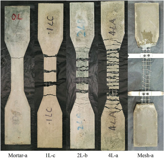
FIGURE 4. Failure modes of specimens under direct tension.
Axial load–deformation relationships of specimens are shown in Figures 5A,B. Load–deformation curves of mesh and ferrocement specimens consisted of three stages. The first stage was approximately linear. When plastic strain reached 0.2%, the specimens stepped into the second stage, yield stage, in which mesh and ferrocement specimens exhibited excellent ductility. Benefited by the strain-hardening behavior of SSWM, ferrocement specimens displayed growing strength after yielding. After specimens reached the peak load, stainless steel wires continuously fractured with loading capacity sharply deteriorated in the last stage.
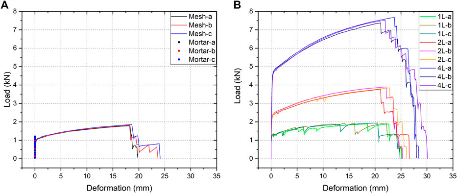
FIGURE 5. Axial load–deformation relationships of mesh, AAS mortar, and ferrocement. (A) Mesh and AAS mortar specimen and (B) AAS ferrocement specimen. A10M.
Compared to the mesh specimens, ferrocement with one layer of SSWM performed better in both yield strength and peak strength. The mesh reached its maximum stress only at cracks in a ferrocement specimen, whereas this occurred along its full length in a mesh specimen. The mesh specimens, therefore, exhibited larger deformation than ferrocement ones under the same load level. Moreover, all the welding points in mesh specimens were exposed to the maximum stress. The mesh specimens had higher probability to fracture at the welding points. This explains the phenomenon that the ferrocement specimens with one layer of SSWM had higher peak strength than the mesh ones.
Proportional enhancement was observed at loading capacity with increasing layers of SSWM (Table 2). When the amounts of SSWM increased to two and four layers, the specimens achieved double and four times improvement in both yield strength and peak strength, respectively. Cracking load of ferrocement was mainly associated with tensile strength of mortar, whereas yield and peak load depended on meshes in ferrocement. Cracking load (Pcr,f), yield load (Py,f), and peak load (Pu,f) of AAS ferrocement under tension can thus be predicted by the following equations:
where ft,m is the tensile strength of mortar specimens. Af and Ass are the cross-sectional area of ferrocement and SSWM, respectively. fy,ss and fu,ss are the yield strength and ultimate strength of mesh specimens, respectively. Predicted Pcr,f, Py,f, and Pu,f are given in Table 2. The predicted results are slightly lower than the experimental values. This is because Eq. 1 ignores contribution from meshes, and Eqs 2 and 3 do not reflect influence of mortar between cracks in deformation and fracture of meshes.
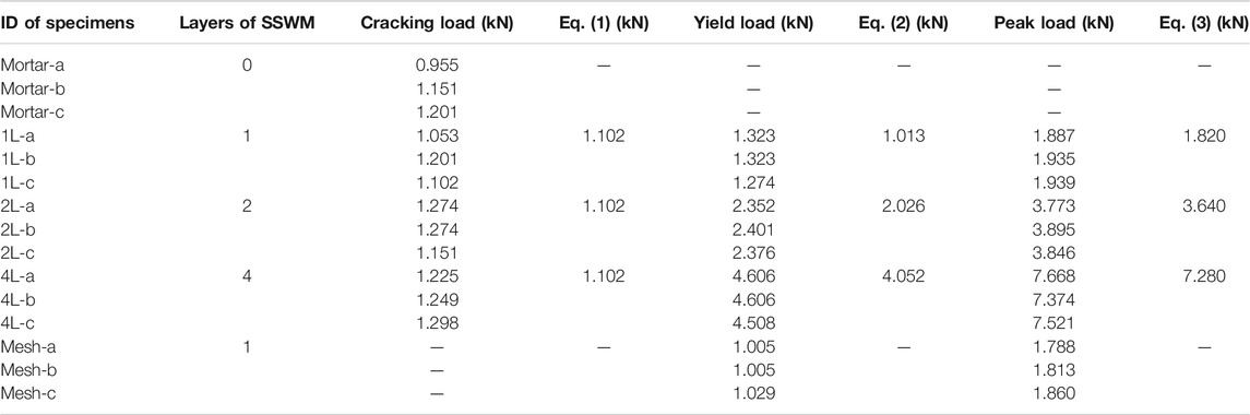
TABLE 2. Experimental results and predictions on tensile capacity of AAS ferrocement
Losses in Mass and Mechanical Properties of Corroded Reinforcements
The accelerated corrosion resulted in obvious longitudinal cracks in column specimens. Corrosion products exuded through the cracks and contaminated the surface of the specimens (Figure 6A). To evaluate the degrees of corrosion, stirrups and main reinforcements at the mid-height of specimens A10M and A20M were removed. There was severe pitting corrosion on both stirrups and main reinforcements (Figures 6B,C). Corrosion was severer at corners of stirrups than that at other parts. The reinforcements were subsequently cleaned in hydrochloric acid solution according to ASTM G1-03(2003). Measure mass losses of main reinforcement were 8.91% and 18.28% in specimens A10M and A20M, which approached objective values of 10% and 20%, respectively. The mass losses of stirrups were 20.98% and 43.22% in specimens A10M and A20M, respectively, more than double those of main reinforcements. This is because stirrups corrode more easily than main reinforcements owing to thinner concrete cover of stirrups. Intact main reinforcements and corroded stirrups formed a corrosion cell, which further exacerbated corrosion of stirrups acting as the anode of the cell (Otsuki et al., 2000). After cleaning with hydrochloric acid, corroded main reinforcements were subjected to tensile tests. They suffered from losses of 11.7% and 22.2% in yield load, severer than those in mass, which reflects adverse effect of pitting corrosion on mechanical performance of reinforcements.
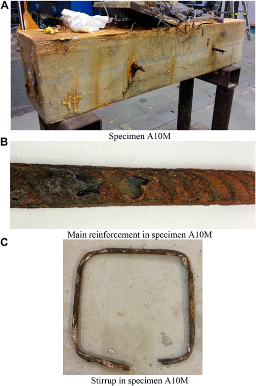
FIGURE 6. Specimen after accelerated corrosion test. (A) Specimen A10M. (B) Main reinforcement in specimen A10M. (C) Stirrup in specimen A10M.
Compressive Performance of Column Specimens
Failure Modes
Failure modes of all specimens are shown in Figure 7. For control specimen A0, crack did not appear until axial load reached its peak of 1117 kN. The first crack appeared and developed parallelly to main reinforcements. With increasing displacement, the crack propagated and new cracks appeared. When axial load was reduced to 85% of its maximum, cracks intersected with each other. Concrete cover spalled off locally (Figure 7A). The concrete cover was removed after test. Main reinforcements were found to have buckled between stirrups. Specimen A0 failed owing to compressive failure of concrete and buckling of main reinforcements.
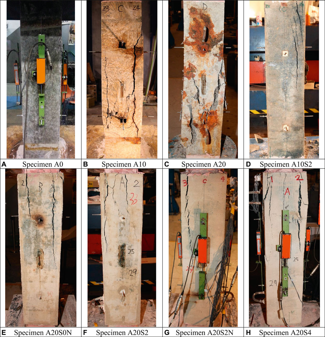
FIGURE 7. Failure modes of specimens under axial compression. (A) Specimen A0. (B) Specimen A10. (C) Specimen A20. (D) Specimen A10S2. (E) Specimen A20S0N. (F) Specimen A20S2. (G) Specimen A20S2N. (H) Specimen A20S4.
Under increasing axial load, corrosion-induced longitudinal cracks widened and propagated rapidly in specimen A10 (Figure 7B). When axial load reached its peak, the longitudinal cracks widened to the maximum width of 5 mm. Concrete cover at mid-height spalled off. Specimen A10 experienced a sudden deterioration in loading capacity. This phenomenon can be explained by an observation on reinforcements of specimen after test. A corroded stirrup at mid-height fractured, which lost confinement to core concrete and resulted in buckling of main reinforcements (Figure 8). Longitudinal cracks fully developed in core concrete.
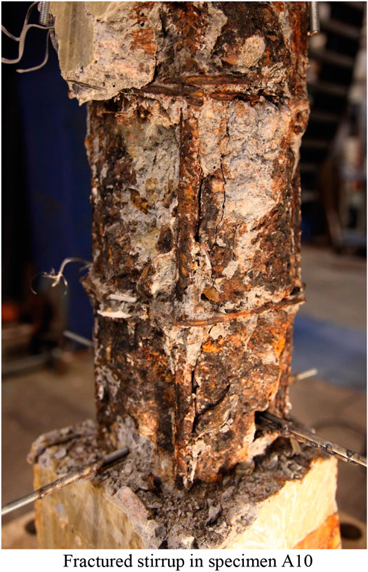
FIGURE 8. Fractured stirrup in specimen A10.
Compared to specimen A10, specimen A20 experienced similar failure mode, lower loading capacity, and severer damage in concrete. Concrete cover of specimen A20 spalled off and exposed main reinforcements (Figure 7C). Stirrups fractured at their corners and lost confinement to core concrete and main reinforcements. Specimen A20 failed due to buckling of main reinforcement and compressive failure of concrete. Stirrups in both specimens A10 and A20 were found to have fractured at corners, which is attributed to serious pitting corrosion.
No crack was found in specimen A10S2 until compressive load reached its maximum of 1104 kN. Specimen A10S2 first cracked at a corner of ferrocement jacket. The crack originated from the top of jacket and developed downward. With increasing axial displacement, a growing number of cracks were formed in the jacket (Figure 7D). Specimen A10S2 lost its loading capacity due to tensile failure of ferrocement jacket. AAS mortar was found crushed inside SSWM (Figure 9). This failure mode is similar to that reported by Kaish et al. (2012). However, specimen A10S2 exhibited a ductile response in post-peak stage because of confinement action provided by SSWM on core concrete.
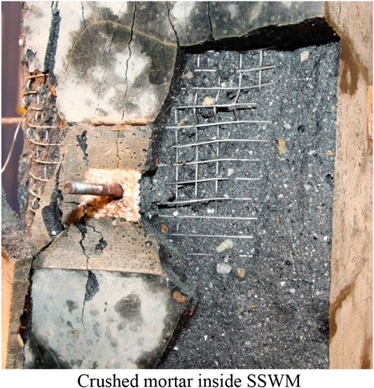
FIGURE 9. Crushed mortar inside SSWM.
Similar to specimen A10S2, specimen A20S0N first cracked at a corner of mortar jacket. With progressive increase in axial displacement, more longitudinal cracks appeared in the mortar jacket (Figure 7E). Width of the cracks on specimen A20S0N was larger than that on specimen A10S2. The corner of jacket spalled in post-peak stage accompanied with prompt deterioration in loading capacity.
Failure of both specimens A20S2 and A20S2N was initiated by longitudinal cracks in ferrocement jackets, and followed by tensile failure of ferrocement and spalling of corners of jacket (Figures 7F,G). Specimen A20S2 achieved peak load close to specimen A20S2N. Owing to confinement of SSWM, loading capacities of specimens A20S2 and A20S2N deteriorated more slowly than that of specimen A20S0N in post-peak stage.
When the specimen A20S4 achieved its peak strength, the first longitudinal crack formed in the middle of ferrocement jacket. Benefited by the highest volume fraction of SSWM, the jacket of specimen A20S4 exhibited the best ductility. In post-peak stage, more longitudinal cracks appeared. Cracks in specimen A20S4 were finer and denser than those in specimen A20S2. Under increasing axial displacement, the corner of ferrocement spalled in succession (Figure 7H). SSWM buckled at the end of the test.
Load–Deformation Relationships
Load–deformation relationships of specimens under axial compression are shown in Figure 10. Control specimen A0 exhibited the highest loading capacity of 1117 kN. Corrosion of reinforcements exerted significant negative effect on mechanical performance of column specimens. Corroded specimens A10 and A20 experienced severe reduction of 28% and 46% in peak load as compared with the control specimen, respectively. The higher the degree of corrosion was, the more severely the specimen deteriorated. The corroded specimens sharply declined in their loading capacity in post-peak stage, which is related to the reduced cross-sectional area caused by spalled concrete. Benefited from ferrocement jackets, strengthened specimens achieved varying degrees of rehabilitation in loading capacity. Specimen A10S2 reached peak strength close to the control one, which demonstrated effectiveness of ferrocement in improvement of loading capacity. Among specimens with degree of corrosion of 20%, specimen A20S4 showed the highest loading capacity of 984.4 kN, followed by specimens A20S2N and A20S2 with 918.4 and 879.9 kN, respectively. Specimen A20S0N carried a load of 819.5 kN and ranked the fourth, whereas corroded specimen A20 performed the lowest strength of 603.7 kN. All the strengthening schemes improved axial compressive strength of corroded specimens. Moreover, new stirrups and ferrocement jackets are beneficial to postpone the degradation of loading capacity in post-peak stage. Compared with corroded specimens, strengthened ones, especially specimen A20S4, had better ductility and slower decline in compressive strength, which are attributed to improved confinement to core concrete.
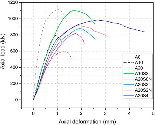
FIGURE 10. Load–deformation relationships of specimens under axial compression.
Both corroded and strengthened specimens showed larger axial deformation than control one A0. For the former, corrosion-induced cracks in concrete deteriorated stiffness of corroded specimens. Axial deformation increased rapidly as the cracks propagated and connected with each other. For the latter, the ferrocement jacket did not carry axial compression directly. The strengthened specimens had smaller compressive area and thus exhibited less stiffness under axial compression. At the initial stage, load–deformation curves of strengthened specimens were close to those of corroded ones under the same degree of corrosion. With increasing load, corrosion-induced cracks rapidly developed and weakened stiffness of corroded specimens, whereas strengthened ones were able to retain their stiffness. Ferrocement jackets stiffened the column specimens.
Strain of main reinforcements of all specimens is shown in Figure 11. Corrosion weakened the cross-section of reinforcements, which resulted in larger compressive strain of main reinforcements in corroded specimens than that in the control one. Specimen A20 showed the maximum strain of reinforcements under the same loading level. As ferrocement jackets provided lateral confinement to main reinforcements, buckling of main reinforcements was suppressed. All main reinforcements in strengthened specimens can carry load after reaching a yield strain of 0.0026. Compared with control specimen, strengthened ones showed larger strain in main reinforcements because of smaller compressive area.
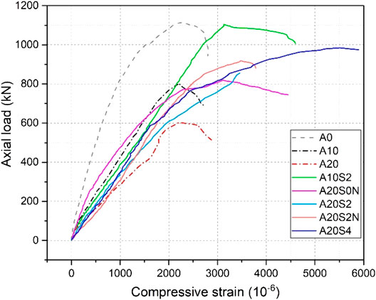
FIGURE 11. Compressive strain of main reinforcements.
Strain of stirrups of all specimens is shown in Figure 12. In the initial stage of test, strain of stirrups was small. With progressive increase in axial load, transverse expansion of core concrete increased the tension in stirrups. Stirrups of specimen A20 displayed maximum tensile strain, which is attributed to its impaired cross-section caused by corrosion. After specimens reached peak load, significant lateral restraint was provided to core concrete by stirrups. Strain of stirrups rapidly increased in post-peak stage. Stirrups in control and strengthened specimens achieved their yield strain of 0.0022 when the specimens failed.
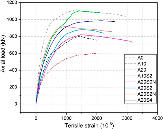
FIGURE 12. Tensile strain of stirrups.
Loading Capacity and Ductility
Yield load Py, peak load Pp, yield deformation Δy, ultimate deformation Δu, and ductility factor of specimens are given in Table 3. Paulay and Priestley (1992) recommended that yield deformation can be obtained from the following equation:
where P’y is the first yield load, taken as 0.75Pp. Δ’y is the deformation corresponding to P’y. Ultimate deformation Δu is the deformation when the load declines to 85% of its maximum (Figure 13). Ductility factor is obtained by Δu divided by Δy.
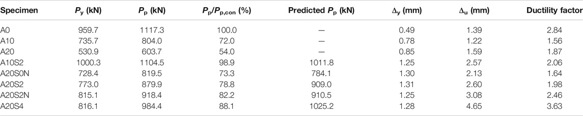
TABLE 3. Loading capacity, deformation, and ductility.
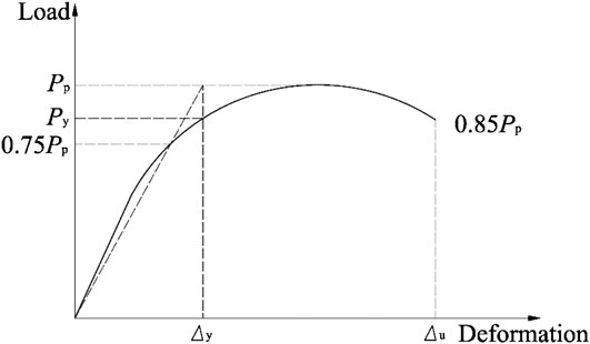
FIGURE 13. Yield load and yield deformation.
As shown in Table 3, the loading capacities of specimens decline with increasing degrees of corrosion. Corroded specimens A10 and A20 suffered reduction of 28% and 46% in compressive strength as compared with the control specimen, respectively. All the proposed strengthening schemes S0N, S2, S2N, and S4 achieved obvious improvement in both yield load and peak load. After strengthened by ferrocement with ρv of 0.266%, specimen A10S2 reached compressive capacity comparable to that of specimen A0. Compared to corroded specimen A20, strengthened specimens A20S0N, A20S2, A20S2N, and A20S4 enhanced loading capacities by 36%, 46%, 52%, and 63%, respectively. Peak load of specimens A20S2 and A20S4 were higher than that of specimens A20S0N and A20S2N by 7.4% and 7.2%, respectively. All the proposed schemes were able to improve axial compressive capacity of columns.
In addition to loading capacity, both ultimate deformation and ductility of specimens were efficiently improved by ferrocement jackets. Ferrocement with ρv of 0.266% increased ductility of corroded specimen A10 by 32%. When the ρv increased to 0.532%, strengthened specimen A20S4 achieved double ductility than specimen A20. SSWM was proved to be more effective than new stirrups in the enhancement of ultimate deformation and postponement of deterioration of loading capacity, which is attributed to high elongation and dense distribution of stainless steel wires in ferrocement.
Prediction of Loading Capacity of Strengthened Columns Under Axial Compression
Saatcioglu and Razvi (1992) proposed a model to predict compressive capacity of columns with lateral confinement as follows:
where f’cc and f’c are the compressive strength of confined and unconfined concrete estimated by cylinders, respectively. fle is the equivalent lateral confinement to core concrete. In this study, the lateral confinement consists of passive confinement pressure from AAS ferrocement and stirrups, as shown in the following equation:
where fl,f and fl,s are the tensile stress of ferrocement jackets and stirrups, which can be obtained from Eqs 8 and (9), respectively,
Here, Py,f is the yield load of AAS ferrocement.
where
where Ac and As are effective cross-sectional area of core concrete and corroded main reinforcements, respectively. fy is the yield strength of main reinforcements. Predicted peak load of strengthened specimen is calculated and given in Table 3. It gets good agreement with experimental results.
Conclusions
In this article, ten full-scale RC columns were prepared. Nine of them were subjected to accelerated corrosion to achieve degrees of corrosion of 8.9% and 18.3% in main reinforcements. Four different strengthening schemes using AAS ferrocement jackets and new stirrups were used. Axial compressive tests were conducted on control, corroded, and strengthened specimens. Effectiveness of the proposed strengthening schemes was experimentally evaluated. Primary conclusions are drawn as follows.
(1) Ferrocement exhibits excellent tensile strength and ductility. Cracking stress of ferrocement depends on the tensile strength of AAS mortar, whereas yield load and ultimate load of ferrocement are related to tensile strength of SSWM.
(2) Chloride causes severe pitting corrosion and weakens the yield load of reinforcements. Corrosion degree of stirrups is severer than that of main reinforcements.
(3) Corrosion of reinforcements severely weakens the loading capacity, stiffness, and ductility of reinforced concrete columns. Corroded specimens fail due to fracture of stirrups at corners and buckling of main reinforcements. Corrosion degrees of 8.9% and 18.3% on main reinforcements result in loading capacity losses of 28% and 46%, respectively. Corroded specimens suffer significant reduction in ductility up to 45%.
(4) AAS ferrocement jackets provide significant improvement in peak load and ductility of corroded specimens. After strengthened using scheme S2, specimen with corrosion degree of 8.9% can rehabilitate loading capacity comparable to control specimen. For specimens with corrosion degree of 18.3%, schemes S2, S2N, and S4 improve their loading capacities from 46% to 63%. Specimen strengthened using scheme S4 achieves approximately two times the ductility than the corroded specimen without strengthening.
(5) Ferrocement jackets provide better and uniform confinement to core concrete than new stirrups. Ferrocement jackets with ρv of 0.266% and 0.532% are recommended to strengthen corroded columns with corrosion degrees of 10% and 20%, respectively.
Empirical models based on confinement effect were proposed to predict the loading capacity of strengthened specimens. The prediction is in good agreement with the experimental results.
Data Availability Statement
The raw data supporting the conclusions of this article will be made available by the authors, without undue reservation.
Author Contributions
The sole author Fang S. conducted the experiments, analyzed the results, established the model for prediction, and drafted this manuscript.
Conflict of Interest
The author declares that the research was conducted in the absence of any commercial or financial relationships that could be construed as a potential conflict of interest.
References
ACI Committee 440. (2002). “Guide for the design and construction of externally bonded FRP systems for strengthening concrete structures, ACI 440.2R-02.” Farmington Hills, MI: American Concrete Institute.
ACI Committee 549. (1997). “State-of-the-art report on ferrocement, ACI 549R-97.” Farmington Hills, MI: American Concrete Institute.
Al-Saidy, A. H., Al-Harthy, A. S., Al-Jabri, K. S., Abdul-Halim, M., and Al-Shidi, N. M. (2010). Structural performance of corroded RC beams repaired with CFRP sheets. Compos. Struct. 92 (8), 1931–1938. doi:10.1016/j.compstruct.2010.01.001
ASTM G1-03. (2003). Standard practice for preparing, cleaning, and evaluating corrosion test specimens. West Conshohocken, PA: American Society for Testing Materials.
Fang, S., Lam, E. S. S., Li, B., and Wu, B. (2020). Effect of alkali contents, moduli and curing time on engineering properties of alkali activated slag. Construct. Build. Mater. 249, 118799. doi:10.1016/j.conbuildmat.2020.118799
Fang, S., Lam, S. S. E., and Wong, W. Y. (2017). Using alkali-activated slag ferrocement to strengthen corroded reinforced concrete columns. Mater. Struct., 50 (1), 35–47. doi:10.1617/s11527-016-0915-4
Haddad, R. H. (2016). Hybrid repair configurations with CFRP composites for recovering structural performance of steel-corroded beams. Construct. Build. Mater. 124, 508–518. doi:10.1016/j.conbuildmat.2016.07.124
Han, L. H., Zheng, Y. Q., and Teng, J. G. (2006). Fire resistance of RC and FRP-confined RC columns. Mag. Concr. Res., 58 (8), 533–546. doi:10.1680/macr.2006.58.8.533
Jayasree, S., Ganesan, N., and Abraham, R. (2016). Effect of ferrocement jacketing on the flexural behaviour of beams with corroded reinforcements. Construct. Build. Mater. 121, 92–99. doi:10.1016/j.conbuildmat.2016.05.131
Joshi, J., Arora, H. C., and Sharma, U. K. (2015). Structural performance of differently confined and strengthened corroding reinforced concrete columns. Construct. Build. Mater. 82, 287–295. doi:10.1016/j.conbuildmat.2015.02.056
Kaish, A. B. M. A., Alam, M. R., Jamil, M., Zain, M. F. M., and Wahed, M. A. (2012). Improved ferrocement jacketing for restrengthening of square RC short column. Construct. Build. Mater. 36, 228–237. doi:10.1016/j.conbuildmat.2012.04.083
Kashi, A., Ramezanianpour, A. A., and Moodi, F. (2017). Durability evaluation of retrofitted corroded reinforced concrete columns with FRP sheets in marine environmental conditions. Construct. Build. Mater. 151, 520–533. doi:10.1016/j.conbuildmat.2017.06.137
Kondraivendhan, B., and Pradhan, B. (2009). Effect of ferrocement confinement on behavior of concrete. Construct. Build. Mater. 23 (3), 1218–1222. doi:10.1016/j.conbuildmat.2008.08.004
Lee, C., Bonacci, J. F., Thomas, M. D., Maalej, M., Khajehpour, S., Hearn, N., et al. (2000). Accelerated corrosion and repair of reinforced concrete columns using carbon fibre reinforced polymer sheets. Can. J. Civ. Eng., 27 (5), 941–948. doi:10.1139/l00-030
Li, F., Zhang, J., Hou, P., and Qu, F. (2013). Experimental study on strengthening effect of bonded steel plate on corroded reinforced concrete beams. Concrete (6), 9–12. doi:10.3969/j.issn.1002-3550.2013.06.003
Li, J., Gong, J., and Wang, L. (2009). Experimental study on seismic behavior of corroded reinforced concrete columns strengthened with concrete jacket and CFRP. China Civ. Eng. J. 42(4), 17–26. doi:10.15951/j.tmgcxb.2009.04.008
Liu, F. (2009). The durable reinforcement and comprehensive anti-corrosion technology of column in Changsha Gulf Bridge. J. Guangdong Comm. Polytechnic., 8 (1), 24–28. doi:10.3969/j.issn.1671-8496.2009.01.008
Meda, A., Mostosi, S., Rinaldi, Z., and Riva, P. (2014). Experimental evaluation of the corrosion influence on the cyclic behaviour of RC columns. Eng. Struct. 76, 112–123. doi:10.1016/j.engstruct.2014.06.043
Meda, A., Mostosi, S., Rinaldi, Z., and Riva, P. (2016). Corroded RC columns repair and strengthening with high performance fiber reinforced concrete jacket. Mater. Struct., 49 (5), 1967–1978. doi:10.1617/s11527-015-0627-1
Otsuki, N., Miyazato, S., Diola, N. B., and Suzuki, H. (2000). Influences of bending crack and water-cement ratio on chloride-induced corrosion of main reinforcing bars and stirrups. ACI Mater. J. 97 (4), 454–464. doi:10.14359/7410.
Pantazopoulou, S. J., Bonacci, J. F., Sheikh, S., Thomas, M. D. A., and Hearn, N. (2001). Repair of corrosion-damaged columns with FRP wraps. J. Compos. Constr. 5 (1), 3–11. doi:10.1061/(asce)1090-0268(2001)5:1(3)
Paulay, T., and Priestley, M. J. N. (1992). Seismic design of reinforced concrete and masonry buildings. Hoboken, NJ: Wiley Interscience Publication.
Peng, J., Li, J., Tang, H., and Zhang, J. (2015). Experimental analysis of strengthening effect of corroded reinforced concrete beams stregnthened with bolted steel plates. J. Civil Architectural and Environmental Engineering., 37 (1), 88–95. doi:10.11835/j.issn.1674-4764.2015.01.015
Roy, D. M. (1999). Alkali-activated cements Opportunities and challenges. Cement Concr. Res. 29 (2), 249–254. doi:10.1016/s0008-8846(98)00093-3
Saatcioglu, M., and Razvi, S. R. (1992). Strength and ductility of confined concrete. J. Struct. Eng. 118 (6), 1590–1607. doi:10.1061/(asce)0733-9445(1992)118:6(1590)
Shi, C. (2003). Corrosion resistance of alkali-activated slag cement. Adv. Cement Res. 15 (2), 77–81. doi:10.1680/adcr.2003.15.2.77
Tastani, S. P., and Pantazopoulou, S. J. (2004). Experimental evaluation of FRP jackets in upgrading RC corroded columns with substandard detailing. Eng. Struct. 26 (6), 817–829. doi:10.1016/j.engstruct.2004.02.003
Keywords: ferrocement, stainless steel wire mesh, corrosion, strengthening, compressive performance
Citation: Fang S (2020) Axial Compressive Performance of Corroded Concrete Columns Strengthened by Alkali-Activated Slag Ferrocement Jackets. Front. Mater. 7:567777. doi: 10.3389/fmats.2020.567777
Received: 30 May 2020; Accepted: 22 September 2020;
Published: 06 November 2020.
Edited by:
Roberto Realfonzo, University of Salerno, ItalyReviewed by:
Stavroula Pantazopoulou, York University, CanadaPaolo Riva, University of Bergamo, Italy
Copyright © 2020 Fang . This is an open-access article distributed under the terms of the Creative Commons Attribution License (CC BY). The use, distribution or reproduction in other forums is permitted, provided the original author(s) and the copyright owner(s) are credited and that the original publication in this journal is cited, in accordance with accepted academic practice. No use, distribution or reproduction is permitted which does not comply with these terms.
*Correspondence: Shuai Fang, ZmFuZ3NodWFpQHNjdXQuZWR1LmNu