 Jian Song Yuan1*Danying Gao2Haitang Zhu1Gang Chen1Liangping Zhao1
- 1College of Civil Engineering, Henan University of Engineering, Zhengzhou, China
- 2School of Water Conservancy Engineering, Zhengzhou University, Zhengzhou, China
Glass fiber reinforced polymer (GFRP) pultruded rectangular tubes were used externally to confine Reinforced Concrete (RC) beams in this experimental study, aiming to improve the corrosion resistance of the RC beams in the harsh environment (e.g., Hydraulic structures and Marine structures). The flexural behavior of the composite beams reinforced with GFRP tubes was investigated by using four-point bending test. The experimental program involved the testing of six beam specimens reinforced with or without the GFRP tubes, and the main parameters investigated included the reinforcement ratio of the tensile steel bars and the stirrup spacing. The experimental results show that the flexural strength and stiffness of the RC beam members were significantly improved by using the GFRP tubes. The brittle failure of the beam specimens was caused by the local failure at one loading pints on the top flange of the GFRP tubes. The higher reinforcement ratio of the tensile steel bars contributed to the improvement of the flexural strength and bending stiffness. The stirrup spacing had little effect on the flexural behavior of the beam specimens in the proposed composite beams.
Introduction
Reinforced concrete (RC) structures normally show enough durability in the ordinary environment. However, in the harsh environment, the durability of RC structures was a serious issue due to the corrosion of the steel bars and concrete (Al-Salloum et al., 2013; Bazli et al., 2016; Elghazy et al., 2017; Berrocal et al., 2018; Biswas et al., 2020). For example, some bridges, oil platforms and other exposed structures in marine environment are becoming functionally deteriorating due to the corrosion problems (Li et al., 2018; Oskouei et al., 2018; Zhou et al., 2019), causing expensive maintenance cost. Therefore, finding novel building materials or technologies to protect the RC structures from the corrosion is significant for the RC structures in the harsh environment.
Fiber reinforced polymer (FRP) composite materials have attracted growing attentions to be the building materials due to the superior corrosion resistance (Micelli and Nanni, 2004; Miyano et al., 2005; Correia et al., 2015; Sankholkar et al., 2018). For example, FRP reinforcements have been used to replace the normal steel bars in some RC structures (Chen et al., 2007; Benmokrane et al., 2017; Elgabbas et al., 2017). By this way, the durability of the RC structures could be apparently improved, especially in the marine engineering and the hydraulic engineering. Currently, many studies have been conducted to investigate the use of FRP reinforcements in the seawater sea-sand concrete (Xiao et al., 2017; Li et al., 2018; Bazli et al., 2019; Zeng et al., 2020), and the corrosion resistance of FRP composites was fully used in seawater sea-sand concrete structures. Using FRP reinforcements can exactly address the corrosion of the steel bars, however, the corrosion resistance of concrete could not be improved after using FRP reinforcements. The durability of the concrete is significantly affected due to the erosion from the chloride and sulfate (Song et al., 2008; Valipour et al., 2017; Kashi et al., 2019), such as the piles in the wharfs. Therefore, how to simultaneously protect the concrete and the reinforcements in RC structures in the harsh environment from the corrosion is also an important research topic (Otieno et al., 2016; Melchers and Chaves, 2020).
FRP pultruded tubes are increasingly investigated in the composite members with the excellent material properties (Hadi and Yuan, 2017; Youssef and Hadi, 2017). For example, Belzer et al. (2013) investigated the flexural behavior of the concrete-filled rectangular glass fiber reinforced polymer (GFRP) tubes. The GFRP tube was employed as the stay-in-place formwork and provide the reinforcement for the beam specimens. Muttashar et al. (2016) tested the flexural behavior of the composite beams reinforced with the GFRP square tubes infilled with concrete. Therefore, the effect of the GFRP pultruded profiles tubes on improving the structural behavior and corrosion resistance of the beam members had been confirmed by these studies (Satasivam et al., 2018; Yuan and Hadi, 2018; Sciarretta and Russo, 2019). Due to the above-mentioned advantages, the GFRP tubes were tried to reinforce the RC beams in this experimental study, aiming to improve the corrosion resistance of the RC structures in the harsh environment as shown in Figure 1. The GFRP rectangular tubes were used as a stay-in-place formwork, and the RC beam members are confined in the GFRP tubes. Since both the steel bars and the concrete are confined by the GFRP tubes, the corrosion resistance of the RC beam members could be significantly improved.
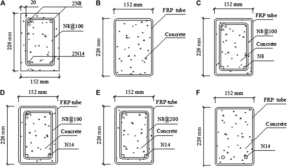
FIGURE 1. Cross-sections of beam specimens (A) RC, (B) G0C, (C) G0.6A, (D) G1.15A, (E) G1.15B, and (F) G1.15C.
Against this background, this paper presents an experimental study on the flexural behavior of the proposed composite beams. The GFRP pultruded tubes were used to reinforce the RC beams. A total of six beam specimens were cast and tested by using four-point bending test. The main parameters included the reinforcement ratio of the tensile steel bars and the stirrup spacing. Investigation of the ultimate load, displacement, strain, and the failure modes of the beam specimens were given. In addition, the effect of each components of the beam specimens on the flexural behavior were also discussed.
Experimental Program
Beam Specimens
In total, six beam specimens with different configurations were tested, including five composite beams reinforced with GFRP tubes and one RC beam. All the composite beam specimens were reinforced with the same GFRP tubes as shown in Figure 2A, and the dimension of the tube is 3,000 mm × 228 mm × 152 mm (Length × Height × Width). The thickness of the GFRP tube was 6 mm. The beam specimens were cast by using the concrete with the same compressive strength, and the aiming compressive strength of which is 40 MPa. The configurations of the beam specimens are summarized in Table 1 and the cross-sections are given in Figure 1. The variables investigated included the reinforcement ratio of the tensile steel bars and the stirrup spacing. The reinforced concrete beam is named as “RC” to be a reference beam, and the reinforcement ratio of the longitudinal tensile bars was 1.15%. Since the reinforcement ratio of 1.15% met the requirement of balanced-reinforced beams and the dimension design of cross-sections in the composite beams, 1.15% was determined as the main reinforcement ratio for most beam specimens. For the composite beams, the name of the specimens starts with the letter “G,” indicating the GFRP rectangular tube is used to reinforce this beam specimen. This letter is then followed by an Arabic number, which means the reinforcement ratio of the tensile steel bars in percent, and three different reinforcement ratios (0, 0.6, and 1.15%) are used. The letter (A, B or C) is finally added to represent the stirrup spacing in shear span, and “A” means the spacing is 100 mm, “B” is 200 mm, “C” means that there are no stirrups in this specimen. For example, Specimen G0.6A refers that this beam specimen is reinforced by the GFRP rectangular tube, and the reinforcement ratio of the tensile steel bars is 0.6%, and the stirrup spacing in the shear span is 100 mm.
TABLE 1. Configuration of beam specimens.
Specimens RC and G1.15C have the same configuration of the steel bars, including the longitudinal steel bars and the stirrups. Therefore, the effect of the GFRP tube was investigated by the comparison of these two specimens. The influence of the longitudinal tensile steel bars was discussed by Specimens G0C and G1.15C, which were reinforced with different tensile steel bars. Specimens G1.15A, G1.15B, and G1.15C were configured with the same reinforcement ratio of the tensile steel bars, and the effect of the stirrup spacing was investigated by the comparison of these three specimens.
It should be mentioned that the bond performance between concrete and GFRP tube is significant for the flexural behavior of the composite beam specimens. Due to the smooth surface of GFRP profiles, several measures normally were suggested to increase the shear strength at the interface, such as using shear connectors or sanding coating. In consideration of the possible strength damage of the GFRP tube caused by installing the shear connectors in the flange, the shear connectors were not used in this study. The interaction between GFRP tube and concrete will been studied as parameter in the future investigations.
Material Properties
All the specimens were cast in one batch by using the self-compacting concrete. The self-compacting concrete was prepared in the lab, and the composition is given in Table 2. The plain concrete cubes (150 mm × 150 mm × 150 mm) were cast to determine the compressive strength of the concrete, in accordance with GB/T 50081 (2002). The compressive strength of the self-compacting concrete was averaged from three cubes was 39.8 MPa at 28 days. The tensile testing on five coupons were conducted to determine the average tensile strength of the steel bars according to the GB/T 228 (2010). The average tensile yield strength of the N14 steel bars was 556.6 MPa, and the modulus of elasticity was 205.4 GPa. The average tensile yield strength of the N8 steel bars was 301.7 MPa with a modulus of elasticity of 190.6 GPa.
TABLE 2. Composition of self-compacting concrete.
The material properties of the GFRP tubes in longitudinal direction were tested. The tensile properties were determined by using ASTM D3039 (2017). Five coupons with a dimension of 250 mm × 25 mm × 6 mm (Length × Width × Thickness) were tested for the average tensile strength. The average tensile strength was 416.5 MPa and the tensile modulus of elasticity was 40.6 GPa. The compressive strength was obtained by using ASTM D695 (2015) and the coupons had a dimension of 125 mm × 25 mm × 6 mm (Length × Width × Thickness). The compressive strength and the compressive modulus of elasticity averaged from the coupon tests were 342.5 MPa and 32.7 GPa, respectively.
Fabrication of Specimens
The fabrication of the beam specimens mainly included following steps. The steel cages were first prepared, and the four strain gages with wires were affixed on the four longitudinal steel bars for each steel cage. The strain gages were fixed in the middle of the longitudinal reinforcements, and enough long strain gages wire was prepared to ensure the convenient connection with the data collection system, as shown in Figure 2B. Then, the prepared steel cages were placed into the formwork. The timber formwork was used for casting Specimen RC, and the GFRP tubes were employed to be the stay-in-place formwork for the composite beams. For all the specimens, a 20 mm cover was left in each side by using the plastic chairs. In addition, two hooks were placed in the two holes located in the shear region for the convenient movement of the beam specimens. The GFRP tube were placed with a 30-degree slop as shown in Figure 2C, which was benefit for the easy casting of the self-compacting concrete. The bottom end of the GFRP tube were covered by using a timber block to ensure the closeness of the tube. Finally, the self-compacting concrete was artificially poured into the tube from the top end, and a custom cover was used to block the top end and ensure the good casting, as shown in Figure 2C. Specimen RC was covered with a wet hessian to prevent the moisture loss and watered during weekdays. The composite beam specimens were cured in the ambient environment until the testing day.
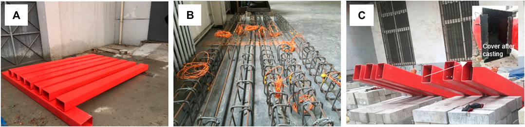
FIGURE 2. (A) GFRP tubes, (B) steel cages, and (C) GFRP tubes with steel cages.
Test Setup
The flexural tests were conducted by using a four-point bending test as shown in Figure 3. All the beam specimens had a clear span of 2,700 mm. The length of the shear span and the pure bending region was 900 mm. Five linear variable differential transformers (LVDTs) were evenly installed at the bottom of the beam specimens to monitor the development of the deflection. The bond behavior between the concrete and the GFRP profiles is normally weak, therefore, two other LVDTs were horizontally placed at two ends of the specimens to measure the relative slip during the tests.
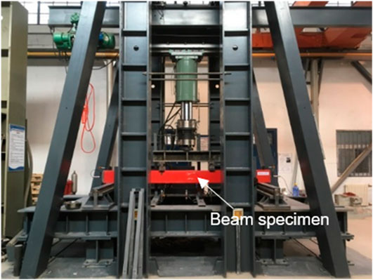
FIGURE 3. Test setup.
The strain gages were employed to measure the strain of the longitudinal reinforcements and the GFRP tubes. As shown in Figure 4, the strain gages were affixed on each longitudinal steel bars before casting the concrete. The compressive strain of the compressive steel bars was achieved by averaging the strain gages S1 and S2. The average tensile strain of the tensile steel bars was obtained by using the strain gages S3 and S4. For FRP tubes, two stain gages (S5 and S6) were fixed in the middle of the top flange to monitor the average compressive strain. In addition, two strain gages (S7, S8) were evenly bonded in the middle of the web to investigate the strain distribution in the midspan cross-section. The average tensile strain of the bottom flanges was tested by strain gages S9 and S10. All the strain gages in the GFRP tubes were placed in the longitudinal directions.
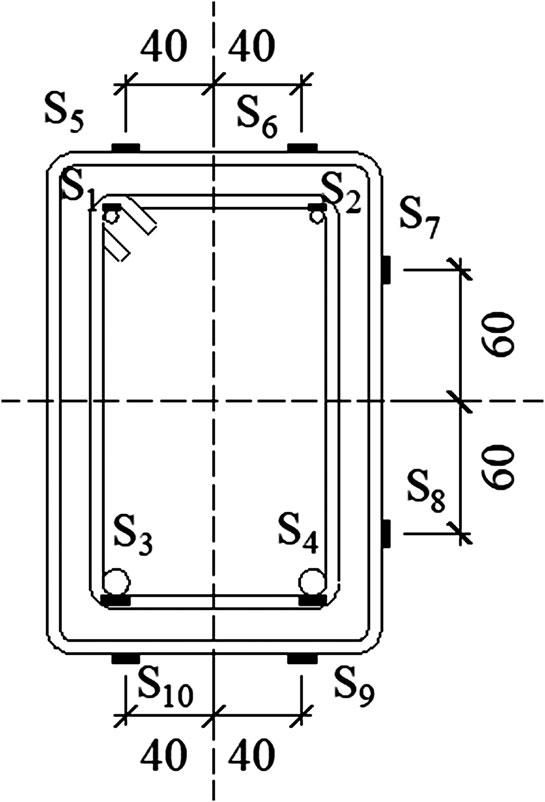
FIGURE 4. Layout of strain gages (mm).
The displacement-controlled load was used by using the 2,000 kN universal testing machine. The loading rate was 0.5 mm/min. The load and displacement data were collected by an electronic data logger connected with a computer every 3 s. The loading of Specimen RC was stopped when the load decreased to 80% of the ultimate load. For the composite beam specimens, the tests were terminated once the ultimate load was reached.
Experimental Results
The experimental results of the flexural test are summarized in Table 3, including the yield load, the ultimate load and the corresponding midspan deflection, the ultimate moment, the initial bending stiffness, and average relative slip as well. It should be noted that the yield point of the beam specimens only could be found in Specimens RC, G1.15A, G1.15B, and G1.15C, and no apparent yield points were observed for Specimens G0C and G0.6A. Moreover, the initial bending stiffness of the specimens with yield point was defined as the stiffness from the point with a load of 30 kN to the yield point. For the beam specimens without apparent yield points, the bending stiffness was defined from the point with a load of 30 kN to the ultimate load.
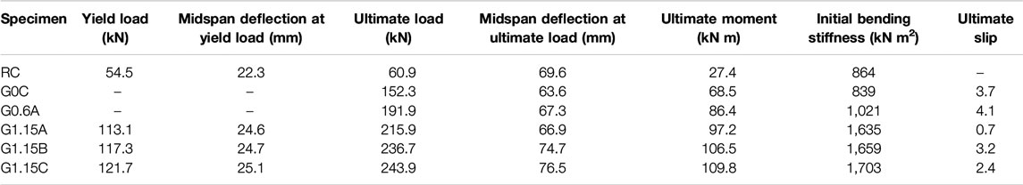
TABLE 3. Experimental results.
General Behavior
In the beginning of the tests, the load and deflection of the beam specimens gradually increased. No obvious damage or crack were found on the external surface of the GFRP tube. Then, the relative slip between the concrete and the GFRP tube was found accompanied with some sounds. When reaching to the ultimate load, a huge explosive sound was heard for all the composite beams. This explosive sound was caused by the sudden failure of the GFRP tubes. As shown in Figure 5, the composite beam specimens failed due to the damage of the GFRP tubes. The damage occurred at one of the loading points, and the tube was torn at the top edge. Apart from the damage at the loading point, the other part of the GFRP tube was intact without obvious damage. As a result, the damaged composite beam specimens still possessed high residual strength. Since the midspan deflection of the damaged specimens had exceeded the full scale of the testing machine, the accurate residual strength of the composite beam specimens was not obtained in this experimental study.
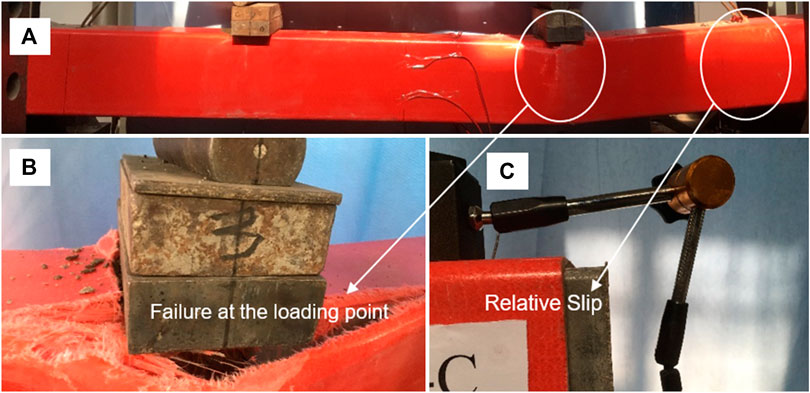
FIGURE 5. (A) Failure of specimens, (B) failure at the loading point, and (C) relative slip.
The failure mode of the concrete core was investigated by removing the GFRP tube after the tests, and the typical distribution of the cracks was given as shown in Figure 6. The number of the cracks was fewer compared with the normal RC beams, while the width of which was larger. The most cracks were through cracks and distributed in the pure bending region. One main crack was found under one loading point where the failure of the GFRP tube occurred. The different distribution between the RC beams and the composite beams was mainly caused by the GFRP tubes. In shear regions, the use of GFRP tubes improved the shear strength of the specimens, therefore, almost no shear crack was in the shear span. Meanwhile, the stiffness of the composite beams was improved by the GFRP tubes, thus reducing the deflection and the number of the cracks in the pure bending regions. In addition, the confinement of the GFRP tube also benefited for the decrease of the cracks.
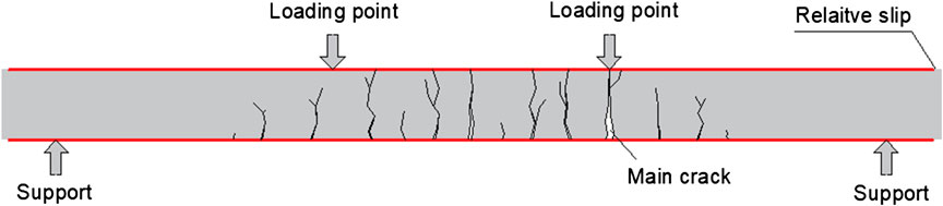
FIGURE 6. Distribution of concrete cracks.
All the composite beams performed similar failure mode by the local failure at one loading point. The failure mode in this study was different from the usual flexural failure mode or shear failure mode in RC beams, since both the pure bending region and the shear region of the GFRP tube were intact when the beam specimens failed. In the end of the tests, the local pressure from the steel plate was large, and this pressure easily caused the local damage of the FRP tubes in the top flange. The local failure of the top flange further caused the failure of the beam specimens. Therefore, the failure mode of the composite beam specimens was the local failure at the loading point.
Load-Midspan Deflection Curves
The load-midspan deflection curves of the beam specimens are given in Figure 7. Specimen RC shows the typical load-midspan deflection curve of RC beam, with a linear increment before the yield point and a long yield platform stage after the yield point. The curve of Specimen G0C shows an almost linear increase up to the failure of the specimen. The fluctuations of the curves were found in this curve as shown in Figure 7, which should be caused by the fracture of the concrete core. The concrete in Specimen G0C was only reinforced by the GFRP tube, without the reinforcement of the steel bars, the concrete easily cracked when encountering large deformation. The bending stiffness of Specimen G0C was approximately same with that of Specimen RC in the beginning of test. Then, after the yield of the steel bars, the stiffness of Specimen RC decreased while Specimen G0C kept constant.
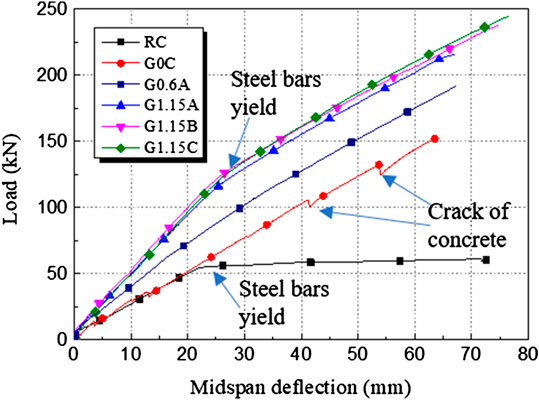
FIGURE 7. Load-midspan deflection curves.
The curve of Specimen G0.6A was smoother after the longitudinal steel bars and stirrups were used. Meanwhile, the load of Specimen G0.6A almost linearly increased up to the ultimate load. The stiffness and ultimate load of Specimen G0.6A were apparently higher compared with Specimens RC and G0C.
Specimens G1.15A, G1.15B, and G1.15C shows similar curves. Based on the results plotted in Figure 7, the increase of the curves could be identified into two stages. The first stage started from the beginning of the test to the yield of the specimens, and the three specimens kept almost same initial bending stiffness and the yield load. The second stage started after the yield point, bending stiffness of the specimens was slightly reduced, while the loads kept ever-increasing until the failure of the specimens. The ultimate loads of these three specimens show little difference although the three specimens had different stirrup spacing.
Slip
The slip-midspan deflection curves are given in Figure 8, and the slip was obtained by averaging the two LVDTs at the ends of the beam specimens. Figure 8 show that the maximum slip was found in Specimens G0C and G0.6A, and the slip almost was more than 4 mm. For Specimens G1.15B and G1.15C, the growth rate and the maximum value of the slip were smaller than the former two specimens. Specimen G1.15A showed the least slip among all the composite beams.
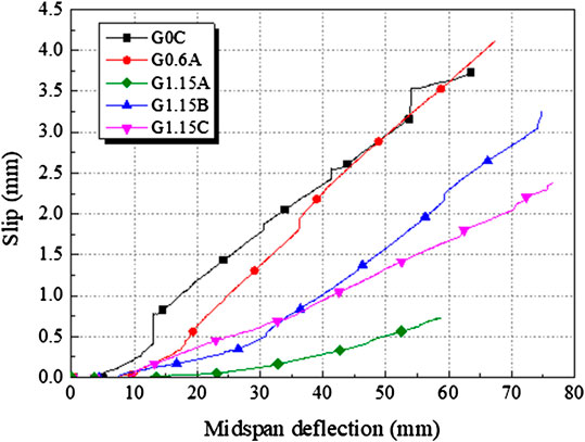
FIGURE 8. Slip-midspan deflection curves.
The relative slip in the composite beams was mainly caused by the crack of the concrete and the deformation of the beam specimens. After the tensile steel bars and the stirrups were used, the concrete was confined by the steel bars and the deformation of beam specimens was controlled, thus reducing the number and width of the concrete cracks, and the relative slip was limited. In addition, the relative slip showed a more rapid growth when the deflection reached to about 30 mm, where the tensile steel bars yielded. The yield of the steel bars caused the wider crack, that is the reason why the relative slip started to rapidly increase when the deflection was about 30 mm.
Ductility
The composite beams (Specimens G1.15A, G1.15B, and G1.15C), the tensile steel bars (N14) of which had apparent yield point, showed an approximately bilinear ascending branch before the peak lead. The load of these three composite beams continued to increase after the yield of the tensile steel bars. The composite beams finally failed with the sudden drop of the load, and did not showed good ductile behavior. Although Specimen G0.6A was also reinforced with longitudinal reinforcements, the yield of the beam specimen was not observed. The reason is that the tensile steel bars (N8) used in this research study had no apparent yield points. As a result, Specimen G0.6A performed a linear growth of load and brittle failure mode. Specimen G0C did not show any ductility due to the lack of the steel bars in this specimen. The steel bars contributed to the improvement of the ductility, however, the brittle failure mode for the composite members was not resolved in this study.
Analysis and Discussion
Effect of GFRP Rectangular Tube
The effect of the GFRP tubes could be apparently observed by the comparison between Specimens RC and G1.15A, as shown in Figure 9. These two specimens had the same reinforcement ratio of the longitudinal bars and the stirrups, and the only difference is that the GFRP tube was used in Specimen G1.15A. The experimental results show that the ultimate load of Specimen G1.15A was improved by three times compared with that of Specimen RC, and the initial bending stiffness doubled. The improvements of the strength and the stiffness were also found when the other composite specimens were compared with Specimen RC. Therefore, the strength and the stiffness of the RC beam members could be significantly improved by using the GFRP tubes. Moreover, no steel stirrups were used in Specimen G1.15C, while Specimen G1.15C showed the superior flexural behavior without shear failure, thus indicating that the GFRP tube could provide enough shear strength. As a result, the use of the tensile steel bars and stirrups could be reasonably reduced in this type of the beam specimens, and the high mechanical properties of the GFRP profiles tubes could guarantee the sufficient flexural behavior.
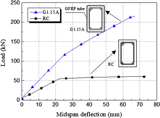
FIGURE 9. Load-midspan deflection curves (specimen G1.15A and specimen RC).
The strain-midspan deflection curves of Specimen G1.15B is given in Figure 10, including the strain of the top flange, bottom flange and the web as well. In general, the strain of each part of the GFRP tube shows a linear increase to the ultimate value. The increasing compressive strain indicates that the top half section of the GFRP tube provided high compressive strength for the composite beams. The increasing tensile strain proves that the GFRP tube could provide high tensile strength for the beam specimens. Moreover, the tensile strain was found apparently larger than the compressive strain, indicating that the GFRP tube contributed more tensile properties than the compressive properties in the composite beams. The other specimens showed the similar strain curves to Specimen G1.15B.
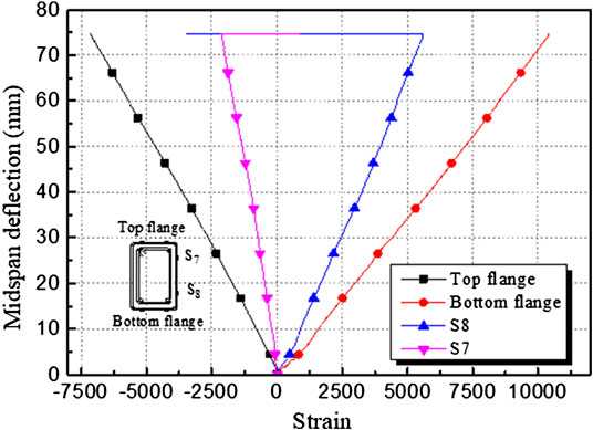
FIGURE 10. Strain-midspan deflection curves (specimen G1.15B).
The compressive strain of the top flange for all the GFRP tubes is shown in Figure 11. Although the reinforcement ratio of the composite beam specimens was different, the compressive behavior of the top flange had no apparent difference. All the compressive strain shows linear increase and the maximum value of which reached about 6,500. The strain analysis and the failure mode of the top flange demonstrated that the ultimate load of the beam specimens was controlled by the top flange of the GFRP tubes.
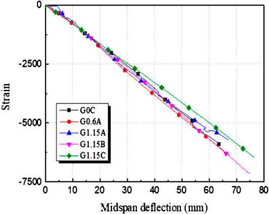
FIGURE 11. Compressive strain-midspan deflection curves of all GFRP tubes.
In addition, although the maximum compressive strain of the GFRP tube was much higher than the ultimate compressive strain of the concrete, the concrete in compression was found not to be crushed. This could be caused by two reasons: a) the concrete was well confined by the GFRP tube, thus improving the compressive behavior of concrete; and b) the crack in tension side of the concrete caused apparent relative slip between the concrete and the tube, so the ultimate compressive strain of the concrete was not reached.
Effect of Stirrups
The effect of the stirrups on the flexural behavior was estimated by the comparison among Specimens G1.15A, G1.15B, and G1.15C as shown in Figure 7. The difference of the three specimens was the stirrup spacing (100 mm in G1.15A, 200 mm in G1.15B, and no stirrups in G1.15C). These three beam specimens showed similar load-midspan deflection curves, including the approximately same yield points and bending stiffness. Therefore, the flexural behavior was not significantly affected by using the stirrups. The ultimate flexural loads were not improved when more stirrups were used in the shear span. Conversely, using more stirrups caused the slight decrease of the ultimate flexural load in Specimen G1.15A. The possible reason may be that using more stirrups in the composite beams caused narrower space between the stirrups and the tubes, affecting the casting of self-compacting concrete, and finally reduced the flexural behavior of the composite beams.
Effect of Tensile Steel Bars
The flexural strength and stiffness of the composite beams was significantly improved when the tensile steel bars were adopted. For example, when two tensile steel bars were employed in Specimen G0.6A, the ultimate load of which was 26% higher than that of the Specimen G0C. When the steel reinforcement ratio was increased to 1.15% in Specimen G1.15C, the flexural strength and stiffness were further improved, as shown in Figure 12. In addition, the tensile properties of the longitudinal steel bars significantly affected the ductile response of the composite beams. If the tensile steel bars have a yield point, the composite beams also performed apparent yield point, such as Specimen G1.15C reinforced by steel bars N14. Conversely, the composite beams showed almost linear load-midspan deflection curve if the tensile steel bars have no yield point, such as Specimen G0.6A reinforced by steel bars N8.
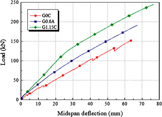
FIGURE 12. Load-midspan deflection curves (specimens G0C, G0.6A, and G1.15C).
As shown in Figure 11, the reinforcement ratio of the tensile steel bars had little influence on the compressive behavior of the top flange of the GFRP tube. However, the tensile behavior of the bottom flange was significantly affected by the tensile steel bars, as shown in Figure 13. Therefore, the use of the tensile steel bars contributed to the full use of the tensile properties of the GFRP tubes, thus improving the flexural strength of the composite beams.
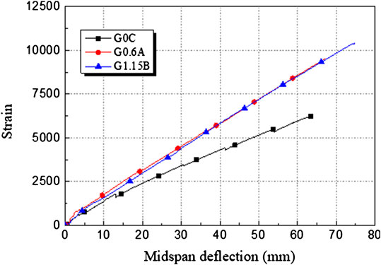
FIGURE 13. Effect of tensile steel bars on the tensile behavior of the bottom flange.
Neutral Axis
The location of the neutral axis was determined based on the compressive strain of the top flange and the tensile strain of the bottom flange in the GFRP tubes. The height of the axis was the distance from the bottom flange of the GFRP tube to the location of the neutral axis. As shown in Figure 14, for the composite beams reinforced with GFRP tube and tensile steel bars, the height of the neutral axis was about 140 mm (2/3 beam depth). The height of the neutral axis of Specimen G0C is about 120 mm, and the existence of the tensile steel bars increased the height of the neutral axis. The location of the neutral axis proved that the majority of the GFRP tubes was used for tension in the composite beams.
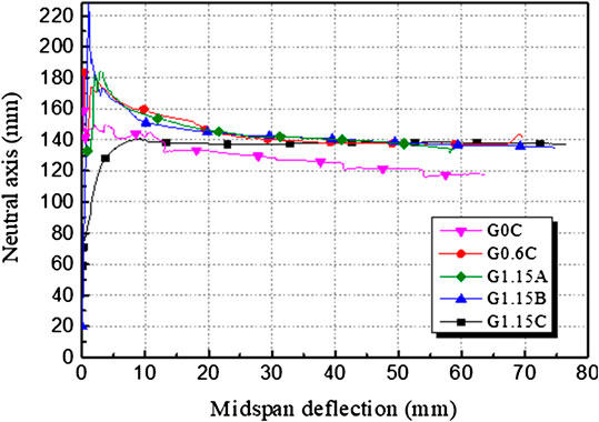
FIGURE 14. Location of the neural axis.
Figure 15 shows the strain distribution of GFRP tube in the midspan (Specimen G1.15B), which shows the same location of the neutral axis as Figure 14. In addition, the distribution of the strain in the midspan of the GFRP tube was confirmed to be a linear distribution in the flexural test. This conclusion is significant for predicting the flexural strength of the composite beams. It should be mentioned that the location of the neutral axis was determined by the strain of the GFRP tube. Since the relative slip occurred between the concrete and the tube, the location of the neutral axis probably had some difference in the concrete and in the GFRP tubes.
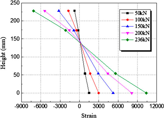
FIGURE 15. Distribution of strain in the midspan (G1.15B).
Conclusions
This study investigates the flexural behavior of the RC beams reinforced with GFRP tubes, and the GFRP tubes were employed to improve the corrosion resistance of the RC beams in the harsh environment. The parameters included the reinforcement ratio of the tensile steel bars and stirrups. All the beam specimens were subjected to the four-point bending test. The experimental results are presented and the effect of each components were analyzed. The following conclusions and results were revealed.
• The flexural strength and stiffness of the beam specimens reinforced by GFRP tubes were much higher than the RC beams. When RC beams were reinforced by the GFRP tubes, the flexural strength was also improved by three times and the bending stiffness doubled. Therefore, the reinforcement ratio of the tensile steel bars could be properly reduced in this type of composite beams due to the high mechanical properties of the GFRP tubes.
• The GFRP tubes could provide high shear strength for the composite beam specimens. As a result, the stirrups used in the beam specimens had little effect on the shear behavior of the composite beam specimens, and the use of the stirrups could be reduced or omitted.
• The GFRP tubes performed both the compressive strength and the tensile strength for the beam specimens. Based on the analysis of strain, the GFRP tube contributed more tensile strength than the compressive strength.
• The composite beams reinforced with the GFRP tubes and tensile steel bars show some ductile behavior, and the yield of the beam specimens could be observed. However, the brittle failure mode could not be avoided. The reinforcement ratio of the tensile steel bars and the strength of the GFRP tube should be further adjusted to improve the ductile behavior of the composite beam members.
• If the tensile steel bars have a yield point, the composite beams showed apparent yield point when the tensile steel bars yielded. After yield point, the bending stiffness of the composite beams slightly decreased, however, the reduced bending stiffness was still much higher than that of the RC beam specimen. The load carrying capacity continued to increase due to the existence of the GFRP tubes.
• The composite beam specimens failed due to the local failure of the GFRP tubes at one loading point. The bottom flange was always intact without damage during the tests. The improvement of the loading points for the GFRP tube, such as using a steel plate with rounded corners to replace the one with sharp edges, is significant to control the flexural behavior and failure mode of the composite beams.
On the basis of testing results, the flexural behavior the beam specimens are absolutely enough when the GFRP tubes were employed to improve the corrosion resistance of the RC beams. However, the design of the composite beams should be further optimized to ensure the full use of the materials. For example, the depth of the flange or the web for the GFRP tube should be more reasonably designed. The reasonable design of the tube contributes to the cost control and the improvement of the flexural behavior of the composite beam members, since the cost of the GFRP tube was still much higher compared with other construction materials. The reinforcement ratio of the tensile steel bars also should be studied, because the steel bars significantly influenced the ductile behavior of the composite beams.
Data Availability Statement
The raw data supporting the conclusions of this article will be made available by the authors, without undue reservation.
Author Contributions
JY: Conceptualization, methodology, writing — original draft preparation, project administration and funding acquisition. GC and LZ: Experimental. GC: Analysis. DG and HZ: Writing — review and editing.
Funding
The authors appreciate the financial support from the National Natural Science Foundation of China (NSFC) (Project No. 51909078) and Key Scientific and Technological Project of Henan Province (Project No. 202102310585).
Conflict of Interest
The authors declare that the research was conducted in the absence of any commercial or financial relationships that could be construed as a potential conflict of interest.
References
Al-Salloum, Y. A., El-Gamal, S., Almusallam, T. H., Alsayed, S. H., and Aqel, M. (2013). Effect of harsh environmental conditions on the tensile properties of GFRP bars. Compos. B Eng. 45 (1), 835–844. doi:10.1016/j.compositesb.2012.05.004
ASTM D695-15 (2015). Standard test method for compressive properties of rigid plastics. Singapore: ASTM International.
ASTM D3039-17 (2017). Standard test method for tensile properties of polymer matrix composite materials. Singapore: ASTM International.
Bazli, M., Ashrafi, H., and Oskouei, A. V. (2016). Effect of harsh environments on mechanical properties of GFRP pultruded profiles. Compos. B Eng. 99, 203–215. doi:10.1016/j.compositesb.2016.06.019
Bazli, M., Zhao, X.-L., Bai, Y., Singh Raman, R. K., and Al-Saadi, S. (2019). Bond-slip behaviour between FRP tubes and seawater sea sand concrete. Eng. Struct. 197, 109421. doi:10.1016/j.engstruct.2019.109421
Belzer, B. E., Robinson, M. J., and Fick, D. R. (2013). Composite action of concrete-filled rectangular GFRP tubes. J. Compos. Constr. 17 (5), 722–731. doi:10.1061/(ASCE)CC.1943-5614.0000370
Benmokrane, B., Ali, A. H., Mohamed, H. M., ElSafty, A., and Manalo, A. (2017). Laboratory assessment and durability performance of vinyl-ester, polyester, and epoxy glass-FRP bars for concrete structures. Compos. B Eng. 114, 163–174. doi:10.1016/j.compositesb.2017.02.002
Berrocal, C. G., Löfgren, I., and Lundgren, K. (2018). The effect of fibres on steel bar corrosion and flexural behaviour of corroded RC beams. Eng. Struct. 163, 409–425. doi:10.1016/j.engstruct.2018.02.068
Biswas, R. K., Iwanami, M., Chijiwa, N., and Uno, K. (2020). Effect of non-uniform rebar corrosion on structural performance of RC structures: a numerical and experimental investigation. Construct. Build. Mater. 230, 116908. doi:10.1016/j.conbuildmat.2019.116908
Chen, Y., Davalos, J. F., Ray, I., and Kim, H.-Y. (2007). Accelerated aging tests for evaluations of durability performance of FRP reinforcing bars for concrete structures. Compos. Struct. 78 (1), 101–111. doi:10.1016/j.compstruct.2005.08.015
Correia, J. R., Bai, Y., and Keller, T. (2015). A review of the fire behaviour of pultruded GFRP structural profiles for civil engineering applications. Compos. Struct. 127, 267–287. doi:10.1016/j.compstruct.2015.03.006
Elgabbas, F., Ahmed, E. A., and Benmokrane, B. (2017). Flexural behavior of concrete beams reinforced with ribbed basalt-FRP reinforcements under static loads. J. Compos. Constr. 21 (3), 04016098. doi:10.1061/(ASCE)CC.1943-5614.0000752
Elghazy, M., El Refai, A., Ebead, U., and Nanni, A. (2017). Effect of corrosion damage on the flexural performance of RC beams strengthened with FRCM composites. Compos. Struct. 180, 994–1006. doi:10.1016/j.compstruct.2017.08.069
GB/T 228 (2010). Metallic materials—tensile testing. Part 1: method of test at room temperature. Beijing: Standards Press of China.
GB/T 50081 (2002). Standard for test method of mechanical properties on ordinary concrete. Beijing: Standards Press of China.
Hadi, M. N. S., and Yuan, J. S. (2017). Experimental investigation of composite beams reinforced with GFRP I-beam and steel bars. Construct. Build. Mater. 144, 462–474. doi:10.1016/j.conbuildmat.2017.03.217
Kashi, A., Ramezanianpour, A. A., Moodi, F., and Malekitabar, H. (2019). Effect of aggressive marine environment on strain efficiency factor of FRP-confined concrete. Construct. Build. Mater. 222, 882–891. doi:10.1016/j.conbuildmat.2019.07.055
Li, Y. L., Zhao, X. L., and Singh Raman, R. K. (2018). Mechanical properties of seawater and sea sand concrete-filled FRP tubes in artificial seawater. Construct. Build. Mater. 191, 977–993. doi:10.1016/j.conbuildmat.2018.10.059
Melchers, R. E., and Chaves, I. A. (2020). Reinforcement corrosion in marine concretes—2. Long-term effects. ACI Mater. J. 117 (2), 217–228. doi:10.14359/51722400
Micelli, F., and Nanni, A. (2004). Durability of FRP rods for concrete structures. Construct. Build. Mater. 18 (7), 491–503. doi:10.1016/j.conbuildmat.2004.04.012
Miyano, Y., Nakada, M., and Sekine, N. (2005). Accelerated testing for long-term durability of FRP laminates for marine use. J. Compos. Mater. 39 (1), 5–20. doi:10.1177/0021998305046430
Muttashar, M., Manalo, A., Karunasena, W., and Lokuge, W. (2016). Influence of infill concrete strength on the flexural behaviour of pultruded GFRP square beams. Compos. Struct. 145, 58–67. doi:10.1016/j.compstruct.2016.02.071
Oskouei, A. V., Bazli, M., Ashrafi, H., and Imani, M. (2018). Flexural and web crippling properties of GFRP pultruded profiles subjected to wetting and drying cycles in different sea water conditions. Polym. Test. 69, 417–430. doi:10.1016/j.polymertesting.2018.05.038
Otieno, M., Beushausen, H., and Alexander, M. (2016). Chloride-induced corrosion of steel in cracked concrete—Part I: experimental studies under accelerated and natural marine environments. Cement Concr. Res. 79, 373–385. doi:10.1016/j.cemconres.2015.08.009
Sankholkar, P. P., Pantelides, C. P., and Hales, T. A. (2018). Confinement model for concrete columns reinforced with GFRP spirals. J. Compos. Constr. 22 (3), 04018007. doi:10.1061/(ASCE)CC.1943-5614.0000843
Satasivam, S., Bai, Y., Yang, Y., Zhu, L., and Zhao, X. (2018). Mechanical performance of two-way modular FRP sandwich slabs. Compos. Struct. 184, 904–916. doi:10.1016/j.compstruct.2017.10.026
Sciarretta, F., and Russo, S. (2019). FE modelling and experimental investigation on adhesive joints between clay brick and pultruded frp profiles. Construct. Build. Mater. 226, 601–615. doi:10.1016/j.conbuildmat.2019.07.291
Song, H.-W., Lee, C.-H., and Ann, K. Y. (2008). Factors influencing chloride transport in concrete structures exposed to marine environments. Cement Concr. Compos. 30 (2), 113–121. doi:10.1016/j.cemconcomp.2007.09.005
Valipour, M., Shekarchi, M., and Arezoumandi, M. (2017). Chlorine diffusion resistivity of sustainable green concrete in harsh marine environments. J. Clean. Prod. 142, 4092–4100. doi:10.1016/j.jclepro.2016.10.015
Xiao, J., Qiang, C., Nanni, A., and Zhang, K. (2017). Use of sea-sand and seawater in concrete construction: current status and future opportunities. Construct. Build. Mater. 155, 1101–1111. doi:10.1016/j.conbuildmat.2017.08.130
Youssef, J., and Hadi, M. N. S. (2017). Axial load-bending moment diagrams of GFRP reinforced columns and GFRP encased square columns. Construct. Build. Mater. 135, 550–564. doi:10.1016/j.conbuildmat.2016.12.125
Yuan, J. S., and Hadi, M. N. S. (2018). Friction coefficient between FRP pultruded profiles and concrete. Mater. Struct. 51 (5), 120. doi:10.1617/s11527-018-1250-8
Zeng, J. J., Duan, Z. J., Guo, Y. C., Xie, Z. H., and Li, L. J. (2020). Novel fiber-reinforced polymer cross wrapping strengthening technique: a comparative study. Adv. Struct. Eng. 23 (5), 979–996. doi:10.1177/1369433219884451
Keywords: flexural behavior, RC beams, concrete, GFRP, pultruded tubes
Citation: Yuan JS, Gao D, Zhu H, Chen G and Zhao L (2020) Flexural Behavior of Reinforced Concrete Beams Reinforced with Glass Fiber Reinforced Polymer Rectangular Tubes. Front. Mater. 7:577299. doi: 10.3389/fmats.2020.577299
Received: 29 June 2020; Accepted: 27 August 2020;
Published: 25 September 2020.
Edited by:
Yingwu Zhou, Shenzhen University, ChinaReviewed by:
Jiafei Jiang, Tongji University, ChinaIonut Ovidiu Toma, Gheorghe Asachi Technical University of Iaşi, Romania
Copyright © 2020 Yuan, Gao, Zhu, Chen and Zhao. This is an open-access article distributed under the terms of the Creative Commons Attribution License (CC BY). The use, distribution or reproduction in other forums is permitted, provided the original author(s) and the copyright owner(s) are credited and that the original publication in this journal is cited, in accordance with accepted academic practice. No use, distribution or reproduction is permitted which does not comply with these terms.
*Correspondence: Jian Song Yuan, eXVhbmppYW5zb25nQGhvdG1haWwuY29t