 Alexandra Glover
 John G. Speer
 Emmanuel De Moor
- 1Los Alamos National Laboratory, Los Alamos, NM, United States
- 2Advanced Steel Processing and Products Research Center, Colorado School of Mines, Golden, CO, United States
The addition of a tempering or austempering step to the double soaking of a 0.14C–7.17Mn (wt pct) steel was investigated in the present contribution. The double soaking heat treatment is a two-step intercritical annealing heat treatment, which generates microstructures of athermal martensite, retained austenite and ferrite when applied to medium manganese steels. Microstructures following double soaking and (aus)tempering contained a combination of retained austenite, athermal or tempered martensite, and blocky or bainitic ferrite. X-ray diffraction, dilatometry and transmission Kikuchi diffraction were utilized to investigate microstructural changes which occurred during tempering or austempering. The resulting mechanical properties were measured using uniaxial tensile testing. The double soaking plus tempering heat treatment was shown to generate an ultimate tensile strength of 1,340 MPa in combination with 28 pct total elongation while the double soaking plus austempering heat treatment resulted in an ultimate tensile strength of 1,675 MPa and total elongation of 22 pct. Overall, both novel heat treatments produced a combination of strength and ductility desired for the third generation of advanced high strength steels.
Introduction
Modern automotive designs seek to improve passenger safety while reducing vehicle weight. This requires the development of new third generation advanced high strength steel (AHSS) grades (Matlock and Speer, 2006; Matlock and Speer, 2009; De Moor et al., 2010). The present work considers one of the proposed third generation AHSS, medium manganese steels. Typically, medium manganese steels undergo a single intercritical annealing heat treatment resulting in a microstructure of ferrite and austenite, with retained austenite volume fractions between 5 and 30 vol pct stabilized by carbon and manganese (Miller, 1972; Merwin, 2007; Gibbs et al., 2011). Alternatively, the recently proposed double soaking heat treatment allows for some fraction of ferrite to be replaced by athermal martensite, while still maintaining significant volume fractions of austenite (De Moor et al., 2016). The substitution of athermal martensite for ferrite, present after the application of a single intercritical annealing heat treatment, is achieved through the application of a second intercritical annealing or austenitizing treatment. This results in the formation of additional austenite, which transforms to athermal martensite upon quenching due to a reduced concentration of carbon and manganese (Glover et al., 2017; Glover et al., 2019). The microstructures of double soaked medium manganese steels demonstrate increased strength while maintaining appreciable ductility, with ultimate tensile strengths above 1700 MPa reported in conjunction with total elongations of 15 pct (Glover et al., 2017; Glover et al., 2019). This is consistent with previous studies of medium manganese steels which have shown that small volume fractions of athermal martensite also promote continuous yielding and improve the overall strength-ductility combination of the material (Merwin, 2007; Gibbs et al., 2011; Gibbs et al., 2014; Rana et al., 2015; Steineder et al., 2015; Steineder et al., 2017).
In this paper, the double soaking concept is expanded to consider the addition of a tempering or austempering heat treatment. These additional steps allow for the strength of the BCC microstructural constituents to be further modified, either through the tempering of athermal martensite or the formation of bainitic ferrite during austempering. These heat treatments are referred to as either double soaking plus tempering (DS-T) or double soaking plus austempering (DS-A). Practically, tempering or austempering may be implemented as part of galvanizing or galvannealing heat treatments, which are commonly applied to automotive sheet steels. The variation in cooling following the double soaking heat treatment is intended to represent the inclusion or omission of a quench following the secondary intercritical annealing or austenitizing heat treatment. The DS-T and DS-T heat treatments only consider a single temperature (450°C) as this is the standard temperature for a zinc bath on a continuous galvanizing line, with a range of isothermal holding times.
Materials and Methods
This investigation employs the addition of either a tempering or austempering step to a double soaked medium manganese steel (De Moor et al., 2016; Glover et al., 2017, Glover et al., 2019). The DS heat treatment is shown schematically in Figure 1. The first step, the primary soaking treatment in the intercritical regime, is characterized by primary austenite
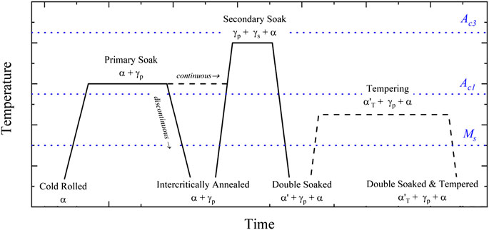
FIGURE 1. Schematic of the double soaking plus tempering (DS-T) heat treatment. Expected changes in microstructure are indicated: ferrite (α), primary austenite (
For the DS-T heat treatment, a water quench is applied between the double soaking and the tempering heat treatment, as shown in Figure 1. This rapid quench to room temperature transforms some fraction of primary and secondary austenite to martensite. The subsequent application of a tempering treatment is expected to reduce the carbon concentration in athermal martensite either through diffusion of carbon to retained austenite or through the precipitation of carbides. During the tempering heat treatment, substantial manganese diffusion is not expected due to the low temperatures and short time scales considered. Upon quenching, the DS-T heat treatment is expected to produce a microstructure of tempered martensite
For the DS-A heat treatment, shown in Figure 2, the material is held at a temperature between the
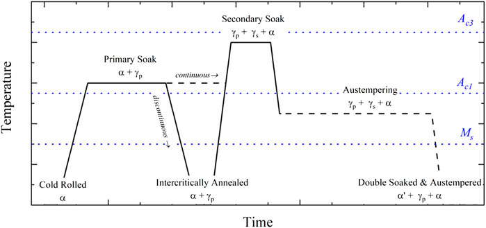
FIGURE 2. Schematic of the double soaking plus austempering (DS-A) heat treatment. Expected changes in microstructure are indicated: ferrite (α), primary austenite (
The DS-T and DS-A heat treatments were applied to a 0.14C–7.17Mn–0.21Si medium manganese steel. Both the DS-T and DS-A heat treatments utilized a commercial batch annealing heat treatment to apply the primary soaking step, while salt pots were utilized to apply the secondary soaking step at 800°C for 30 s followed by the tempering or austempering heat treatment. The microstructural characteristics and mechanical properties produced by this double soaking heat treatment, referred to as DS: 800°C, 30 s, are discussed in greater detail in previous work (Glover et al., 2017). The tempering or austempering heat treatments utilized a single temperature (450°C) and four isothermal hold times, 10, 30, 60 and 300 s.
Dilatometric data sets were gathered using a TA Instruments DIL805A® quench dilatometer. A heating rate of 80°C/s and quench rate of 50 °C/s was implemented for all samples. The temperature corresponding to the onset of a phase transformation was identified utilizing a methodology proposed by Yang and Bhadeshia (2007). This method suggests the onset of transformation can be defined at a critical strain, off-set from the linear regression line for the linear thermal expansion or contraction of the sample. In this investigation a standard off-set of ±0.005 pct strain was used to identify the deviation from linearity which indicates the initiation or cessation of a phase transformation. In all cases this was a more significant off-set than a three standard error off-set.
X-ray diffraction profiles were used to determine retained austenite volume fractions and BCC (α/α′) phase dislocation density. Coupons of each condition considered in this investigation were heat treated using salt pots. Samples were then mechanically ground to 1,200 grit and chemically polished to remove any mechanical deformation from grinding, with a mixture of 1:5:5 hydrofluoric acid, hydrogen peroxide, and water for 300 s, removing approximately 0.5 mm of material. All XRD scans were performed on a PANalytical Empyrean XRD with a Cu-tube (Kα1,λ = 1.541
Retained austenite volume fractions were calculated for each DS heat treatment condition using the Society of Automotive Engineers (SAE) method from the XRD line profiles (Jatczak, 1980). The dislocation density of the BCC (α/α′) phase was estimated based upon peak broadening from the {110}, {200}, {211}, {220}, {310} and {222} orientations of ferrite for each XRD line scan collected from each heat treatment condition. To quantify instrumental broadening for the PANalytical Empyrean XRD, a large grain, polycrystalline silicon wafer was used. Each of the Si diffraction peaks was fit using the PANalytical X’Pert HighScore Plus® software package. The resulting peak widths, characterized as integral breadth (instrumental broadening, βInstrumental), were plotted as a function of scan angle (2θ). To fit the resulting curve, a second order polynomial function was utilized, and the following equation for instrumental broadening:
was determined. For all future calculations which utilize peak width, Eq. 1 was used to remove the effect of instrumental broadening.
After correcting the measured diffraction line profiles for instrumental broadening, a modified Williamson–Hall method was used to calculate dislocation density (Ungár and Borbély, 1996). For isotropic materials, the modified Williamson–Hall method estimates dislocation density due to strain broadening from parameters ΔK and K:
where D is crystallite size, b is Burgers vector, M is a dimensionless constant known as the dislocation distribution parameter taken to be 1.4 (HajyAkbary et al., 2015), ρ is the dislocation density, 2θ describes the position of the peak, λ is the wavelength of the incident beam, and
The average dislocation contrast factor is calculated using Eq. 4 where
The term
The parameters
Elastic constants (Kim and Johnson, 2007) corresponding to a martensitic steel were used in the calculation of A, which resulted in a value close to unity. The average dislocation contrast factor of the {hkl} reflections,
Due to the ultra-fine grain size of the 0.14C–7.17Mn steel, transmission Kikuchi diffraction (TKD), first developed by Keller and Geiss, was implemented in this work (Keller and Geiss, 2012). TKD was preferred as it offered significantly improved spatial resolution, as compared to conventional EBSD, while still making use of the automatic indexing of Kikuchi diffraction patterns provided by the EBSD software (Sneddon et al., 2016). Thin-foil samples, prepared using a FIB lift-out methodology, were approximately 100 nm thick and generally contained a singular grain in the through thickness direction. Samples were held in a PELCO small grid FIB holder and positioned in the JEOL JSM-7000F field emission scanning electron microscope (FESEM) at a standard working distance of 10 mm, tilt of 70° (backtilt of 20°), and an accelerating voltage of 30 kV. Adjustments were also made to the detector settings within the TEAM™ EBSD software. An algorithm of dynamic background subtraction, intensity histogram normalization and median smoothing filter generally produced the best results. A step size of 20 nm was used to collect 6 × 6 μm2 maps, where BCC (ferrite/martensite) and FCC (austenite) were the only phases considered. Following TKD map collection, a clean-up procedure which utilized a nearest neighbor orientation correlation was applied for all grains with a confidence interval of less than 0.003.
Tensile testing was conducted using ASTM E8 subsized samples machined parallel to the rolling direction with a gauge section of 25 mm (ASTM International, 2015). Testing was on a Instron 1,125 screw-driven load frame at a constant engineering strain rate of 4.5 × 10⁻⁴ s−1 in a method consistent with ASTM E8 (ASTM International, 2015). Applied load and crosshead displacement were recorded at a rate of 10 Hz. Sample deformation was monitored using 2D DIC (Sutton et al., 2000). Images were captured using a CCD camera at a frequency of 5 Hz. The resulting data were analyzed using the VIC 2D software (Vic 3D, 2018) to determine engineering strain for a virtual 25 mm gauge length. For each heat treatment condition yield strength (YS, 0.2 pct offset), ultimate tensile strength (UTS), uniform elongation (UE), total elongation (TE) and the strength-ductility product (UTS⋅TE) are reported.
Results
The DS-T and DS-A heat treatments were applied according to the heat treatment schematics presented in Figures 1, 2, respectively. Phase transformations which occurred during the DS-A and DS-T heat treatments were monitored using dilatometry, based upon changes in relative dilatation as a function of temperature and time. As the primary soaking heat treatment was applied using a commercial batch annealing heat treatment the dilatometric data only consider phase transformations which occur during the secondary soaking and the subsequent tempering or austempering heat treatment.
In Figure 3 the phase transformations inferred during each step of the DS-T heat treatment are indicated on a plot of relative dilatation vs. temperature or time for the DS-T: 450°C, 300 s heat treatment. During the application of the secondary soaking heat treatment at 800°C for 30 s, the transformation of BCC ferrite to FCC secondary austenite is evident through a reduction in relative dilatation. Upon quenching from the secondary soaking heat treatment an increase in relative dilatation, characteristic of the martensitic transformation, is evident in Figure 3A. In all of the DS-T heat treatment conditions considered the Ms temperature is relatively consistent, occurring between 306 and 310°C. Upon reheating to the tempering temperature, no deviations from linearity are evident in the relative dilatation vs. temperature plot, shown in Figure 3A. During the tempering hold shown in Figures 3B a small increase in relative dilatation is observed, which may be due to a small amount of austenite decomposition to BCC ferrite (Hidalgo et al., 2017). Volume contraction, which may be expected to result from a reduction in martensite carbon concentration as a result of the tempering, is not observed during the tempering hold shown in Figure 3B. This may be due to the low carbon concentration of athermal martensite, which would reduce the magnitude of this contraction, allowing it to be obscured by the more significant expansion attributed to austenite decomposition (Cheng et al., 1990). Quenching to room temperature following the tempering heat treatment results in linear thermal contraction, indicating that no additional phase transformations occur.
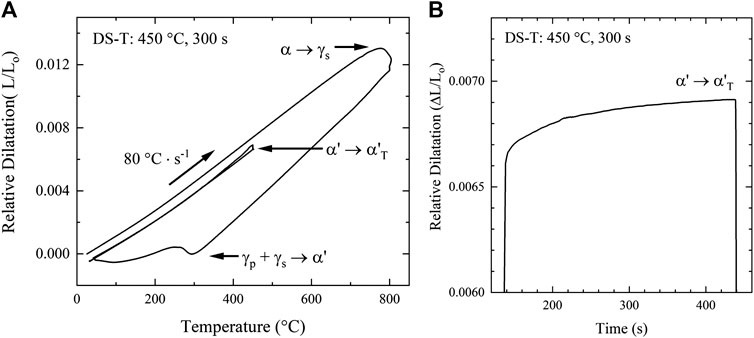
FIGURE 3. (A) Relative dilatation vs. temperature and (B) relative dilatation vs. time for the DS-T: 450°C, 300 s heat treatment. Phase transformations associated with each feature of the dilatometric data are indicated as: ferrite (α), primary austenite (
In Figure 4A the phase transformations inferred during the double soaking and austempering heat treatment are indicated on a relative dilatation vs. temperature curve for the DS-A: 450°C, 300 s condition. Following heating at a rate of 80°C/s, a reduction in relative dilatation during the isothermal hold of the secondary soaking heat treatment is consistent with reduction in volume associated with the transformation of BCC ferrite to FCC secondary austenite. Following the isothermal hold at 800°C, the sample is quenched to the austempering temperature of 450°C. During the austempering hold, the relative dilatation vs. time plot for the DS-A: 450°C, 300 s heat treatment, shown as Figure 4B, indicates volume expansion. This is consistent with the transformation of FCC secondary austenite to BCC blocky and/or bainitic ferrite (Grajcar et al., 2014; Hofer et al., 2016). Growth of blocky ferrite, retained following an intercritical annealing heat treatment, has been observed at temperatures below the intercritical annealing temperature regime (Gallagher et al., 2003; Speer et al., 2004). This results in competition between the growth of blocky ferrite and nucleation and growth of bainitic ferrite during austempering. As both phase transformations would result in a volume expansion, complementary techniques would be required to identify the dominant phase transformation. The transformation of primary austenite to bainitic ferrite would not be expected, as the increased manganese concentration of primary austenite places the bainite start temperature below the austempering temperature of 450°C (Kang et al., 2014). Upon quenching to room temperature, volume expansion consistent with the transformation of FCC austenite to BCC/BCT martensite is evident in Figure 4A. The Ms temperature was measured as 273°C following the DS-A: 450°C, 300 s heat treatment.
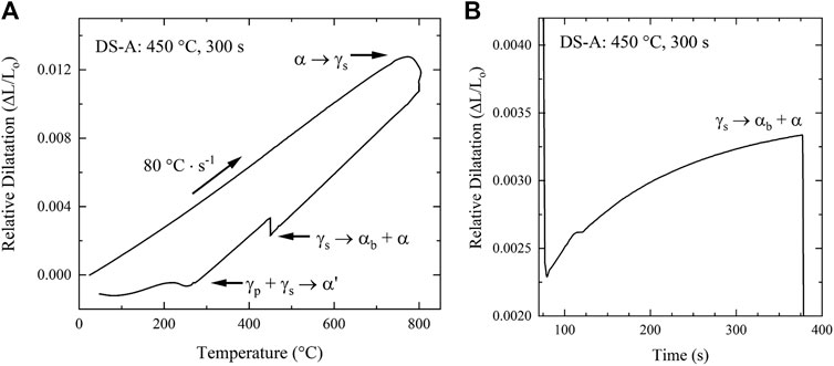
FIGURE 4. (A) Relative dilatation vs. temperature and (B) relative dilatation vs. time for the DS-A: 450°C, 300 s heat treatment. Phase transformations associated with each feature of the dilatometric data are indicated as: ferrite (α), primary austenite (
When examining the range of austempering times considered in this work it was noted that with increasing austempering time at 450°C the Ms temperature is reduced. The reduction in Ms temperature is evident in the plot of relative dilatation vs. temperature for the DS-A heat treatments, shown in Figure 5. For example, the Ms temperature following the DS-A: 450°C, 10 s heat treatment was measured as 299°C, which is reduced to 273°C following the DS-A: 450°C, 300 s heat treatment. This reduction in Ms temperature suggests that the solute concentration of the austenite which transforms to martensite upon quenching has increased as a result of the austempering heat treatment. Solute enrichment of austenite is consistent with the formation of blocky ferrite and/or bainitic ferrite during the austempering heat treatment, with a reduction in solute carbon concentration achieved through carbon partitioning into austenite or carbide precipitation. The reduction in Ms temperature following the austempering heat treatment is consistent with some amount of carbon diffusion into secondary austenite, which transforms to martensite upon quenching.
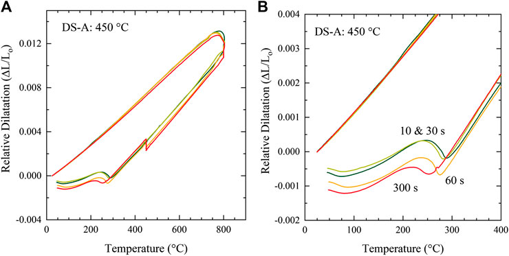
FIGURE 5. (A, B) Relative dilatation vs. temperature for the DS-A heat treatments, indicating trends in Ms temperature with increasing austempering time.
The austenite volume fractions measured using X-ray diffraction after each DS-A and DS-T heat treatment are shown in Figure 6, as a function of tempering or austempering time. The DS: 800°C, 30 s heat treatment is also included. In the DS-T heat treatment conditions, the measured retained austenite volume fractions are relatively constant for the 10, 30 and 60 s tempering heat treatments at 450°C. After a 300 s tempering treatment at 450°C the retained austenite volume fraction appears to be slightly reduced, from 34 vol pct retained austenite after the 60 s tempering treatment, to 29 vol pct retained austenite after the 300 s tempering heat treatment. This suggests that a small amount of austenite decomposition may occur during tempering. In the DS-A heat treatment conditions, the austenite fraction is relatively constant with increasing austempering time, and only varies between 33 and 35 vol pct.
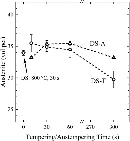
FIGURE 6. Retained austenite volume fraction as a function of tempering or austempering time for the DS-T and DS-A heat treatments (Jatczak, 1980). The retained austenite fraction for the initial condition, DS: 800°C, 30 s, is also indicated. Error bars represent the standard error of three measurements in each heat treatment condition.
The dislocation densities of the BCC (α/α′) microstructural constituents were calculated using a modified Williamson-Hall methodology for each DS-T and DS-A heat treatment condition (HajyAkbary et al., 2015). The calculated dislocation densities for the BCC microstructural constituents are shown as a function of tempering or austempering time in Figure 7. With increasing tempering time, the dislocation density of the BCC microstructural constituents in the DS-T heat treatment condition decreased. For example, the dislocation density following the 10 s tempering hold has been reduced to 1.44 × 10¹⁵ m−2 as compared to the DS: 800°C, 30 s condition with a dislocation density of 3.86 × 10¹⁵ m−2. The final dislocation density, following the tempering treatment at 450°C for 300 s, is 4.7 × 10¹⁴ m−2. The magnitude of dislocation recovery which occurs during tempering is similar to other low-carbon martensitic steels (Swarr and Krauss, 1976; HajyAkbary et al., 2015).
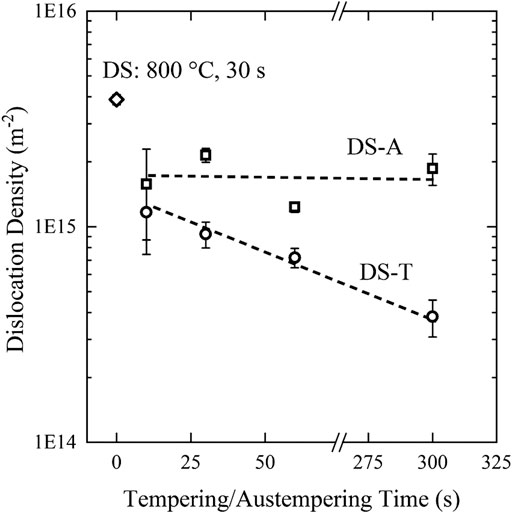
FIGURE 7. Dislocation density as a function of tempering or austempering time for the DS-T and DS-A heat treatments, calculated using the modified Williamson–Hall methodology from XRD line scans (HajyAkbary et al., 2015). Error bars represent the standard error for an average of three measurements in each heat treatment condition.
In the DS-A condition, the dislocation density of the BCC microstructural constituents was constant with increasing austempering time, with an average value of 1.7 × 10¹⁵ m−2. The dislocation densities of the DS-A conditions were reduced compared to the dislocation density of DS: 800°C, 30 s sample, the base condition for all of the DS-A heat treatments. As previously discussed, either bainitic ferrite or blocky ferrite is expected to form during the austempering hold. The dislocation density of bainitic ferrite is slightly reduced as compared to martensite, while the dislocation density of blocky ferrite is expected to be consistent with the low dislocation density of intercritical ferrite (Bhadeshia, 1992). As the formation of blocky and bainitic ferrite was ongoing throughout the austempering heat treatment, as indicated by the volume expansion observed in the relative dilatometric curves shown in Figure 4, the constant value of BCC phase dislocation density with increasing austempering time may suggest that the modification of dislocation density associated with the formation of blocky and/or bainitic ferrite was not significant enough to be reflected in the dislocation density measurements.
TKD maps were made for samples following the DS-A and DS-T heat treatments. In Figure 8, 6 × 6
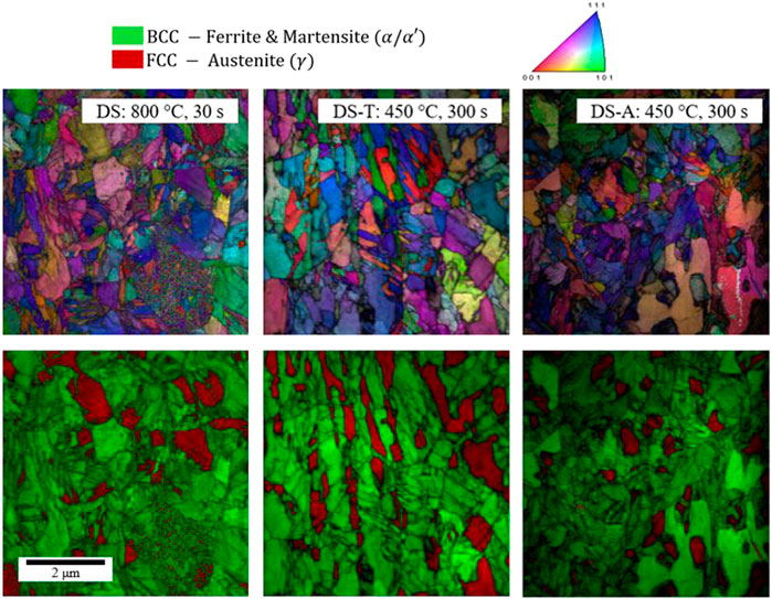
FIGURE 8. TKD phase map overlaid with image quality (top) and inverse pole figure map (IPF) overlaid with IQ (bottom) for the (A) DS:800°C, 30 s (B) DS-T: 450°C, 300 s and (C) DS-A: 450°C, 300 s heat treatment conditions. (Color image - see PDF).
The TKD map of the DS-T: 450°C, 300 s heat treatment condition, shown in Figure 8B, suggests the microstructure is composed of tempered martensite, retained austenite and ferrite. The increased brightness of the BCC phase indicates that overall image quality has increased as compared to the DS: 800°C, 30 s condition, likely due to a reduction in the dislocation density of martensite during tempering. Aside from the increased image quality of the BCC phase, the distribution in grain size appears relatively unchanged from the DS: 800°C, 30 s condition. This is consistent with the microstructural changes observed for tempering of low-carbon lath martensite within this temperature range (Swarr and Krauss, 1976; Krauss, 2017). The measured austenite volume fraction from TKD was 22.2 vol pct as compared to the 19.2 vol pct measured using XRD.
In the DS-A: 450°C, 300 s heat treatment condition the TKD map, shown in Figure 8C, indicates a microstructure of bainite and/or athermal martensite, ferrite, and retained austenite. Bainite cannot be differentiated from athermal martensite as both phases are expected to have a BCC or near BCC crystal structure, fine grain size, and relatively high dislocation density. A few ferrite grains, evident from their large size and increased image quality, are dispersed throughout the DS-A microstructure. Most notably, two large ferrite grains with irregular shapes are present in the bottom right corner of the imaged area. The large size and irregular shape of these ferrite grains are indicative of blocky ferrite growth during austempering. This is consistent with previous studies of austempered TRIP steels containing intercritical ferrite, which suggest that the formation of both bainitic ferrite and blocky ferrite may occur during austempering (Gallagher et al., 2003; Speer et al., 2004). Excluding the two aforementioned ferrite grains, the microstructure is very similar to that of the DS: 800°C, 30 s condition, shown in Figure 8A. The measured retained austenite volume fraction from TKD was 11.8 vol pct in this region, as compared to 19.2 vol pct measured using XRD.
The uniaxial engineering stress-engineering strain and work hardening rate-true stress curves, generated using the DS-T and DS-A heat treatments, are presented in Figures 9, 10, respectively. Only two austempering or tempering heat treatment times, 30 and 300 s, are plotted. This is because the tensile properties were very similar for the DS-A or DS-T heat treatments, across all the tempering or austempering times considered. The measured tensile properties for all the conditions are summarized in Table 1. The application of a tempering treatment was shown to significantly improve the elongation of the 0.14C–7.17Mn steel as compared to the DS: 800°C, 30 s heat treatment condition. Improvements in elongation with the application of the DS-T heat treatment were accompanied by a reduction in UTS. For example, with increasing tempering time, TE increased from 22.9 pct following a 10 s tempering treatment, to 28.3 pct following a 300 s tempering treatment. For these same DS-T conditions, UTS decreased from 1,408 MPa to 1,340 MPa for the 10 s and 300 s tempering treatment, respectively. Following the DS-T heat treatment, YS was substantially increased as compared to the DS: 800°C, 30 s heat treatment condition while UTS was reduced. Additionally, the application of the tempering heat treatment was shown to reintroduce discontinuous yielding and reduce the work hardening rate as compared to the base, DS: 800°C, 30 s heat treatment condition.
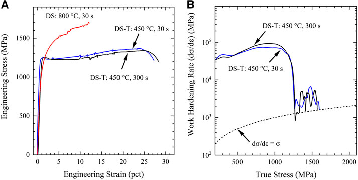
FIGURE 9. (A) Engineering stress-strain and (B) true work hardening rate as a function of true stress for the DS-A 0.14C-7.17Mn steel following austempering at 450°C for 30 or 300 s. The plastic instability criterion (dσ/dε = σ) is indicated by the dashed line.
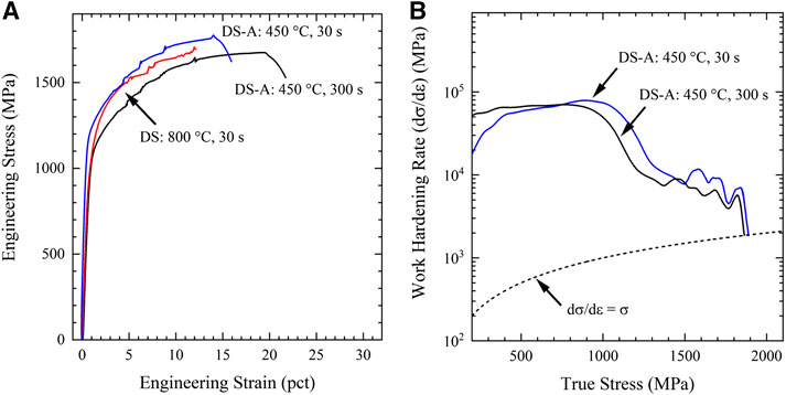
FIGURE 10. (A) Engineering stress-strain and (B) true work hardening rate as a function of true stress for the DS-T 0.14C-7.17Mn steel following tempering at 450°C for 30 or 300 s. The plastic instability criterion (dσ/dε = σ) is indicated by the dashed line.
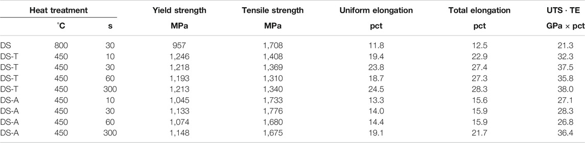
TABLE 1. Tensile properties for the DS-T and DS-A medium manganese steels.
The tensile curves generated using the DS-A heat treatment are shown in Figure 10. All of the DS-A tensile samples demonstrate continuous yielding, similar to the DS: 800°C, 30 s heat treatment condition. Following yielding, all the DS-A samples exhibit a high rate of work hardening, which is reduced slightly with increasing austempering time. Additionally, with increasing austempering time the elongation of the DS-A samples is significantly improved, while UTS is slightly reduced. This is most evident in the DS-A: 450°C, 300 s condition where the TE has increased to 21.7 pct, from 12.5 pct in the base condition (DS: 800°C, 30 s). Comparing these same heat treatments, UTS is reduced by 33–1,675 MPa in the DS-A: 450°C, 300 s heat treatment condition. The combination of increased elongation, while maintaining a high UTS, leads to substantial improvements in the strength-ductility product of the 0.14C-7.17Mn steel with the application of the DS-A heat treatment.
Discussion
The tempering of athermal martensite through the DS-T heat treatment, was found to produce a microstructure with moderate strength and elongation. Discontinuous yielding was reintroduced, likely due to dislocation recovery during the tempering heat treatment, which has been shown to occur at temperatures of 450°C in low-carbon martensitic steels (Swarr and Krauss, 1976; HajyAkbary et al., 2015). A reduction in dislocation density resulting from the DS-T heat treatment was documented through both the modified Williamson-Hall measurements, which suggested a steady reduction in dislocation density across all tempering times considered, as well as the increased IQ of the BCC microstructural constituents in the TKD map of the DS-T: 450°C, 300 s heat treatment condition. Additionally, it should be noted that discontinuous yielding may also be exacerbated by the UFG size of both BCC and FCC microstructural constituents present in the DS-T heat treatment conditions (Carlton and Ferreira, 2007; Morooka et al., 2008; Gao et al., 2014). No additional phase transformations occurred as a result of the tempering heat treatment, as documented using dilatometry.
Following the DS-T heat treatment at 450°C for 10 s YS was increased substantially as compared to the DS: 800°C, 30 s heat treatment condition, from 957 MPa to above 1,200 MPa. The increase in yield strength may be attributed to precipitation of tempering carbides, carbon segregation to dislocations during the tempering heat treatment. The reduction in work hardening rate and UTS are likely related to microstructural changes resulting from the tempering heat treatment. Similar heat treatments, applied to low-carbon martensitic steels, have been shown to reduce dislocation multiplication during plastic deformation, and modify the strain-induced transformation of austenite (Swarr and Krauss, 1976; Hidalgo et al., 2017; Krauss, 2017). Overall, the DS-T heat treatment produced an improved combination of strength and ductility, while demonstrating the importance of athermal martensite and the resulting elevated mobile dislocation density in preventing discontinuous yielding.
The DS-A heat treatment was shown to produce a microstructure containing athermal martensite and retained austenite, along with some fraction of blocky or bainitic ferrite. This resulted in an excellent combination of tensile properties, with significantly improved elongation and only a slight reduction in ultimate tensile strength as compared to the DS: 800°C, 30 s heat treatment. The mechanical properties of the DS-A heat treatment conditions may be linked to microstructural changes which occur during the austempering heat treatment. During the application of the austempering heat treatment, volume expansion was noted in dilatometric data, with the magnitude of the volume expansion increasing with austempering time. This is consistent with the transformation of FCC austenite to BCC blocky or bainitic ferrite. The formation of blocky or bainitic ferrite during the austempering hold was also supported by the TKD map of the DS-A: 450°C, 300 s heat treatment condition, which indicated the BCC microstructural constituents were composed of a mixture of larger blocky ferrite as well as ultra-fine bainitic ferrite and/or athermal martensite. The TKD mapping also indicated that significant volume fractions of austenite were retained following the DS-A heat treatment, consistent with austenite phase fractions measured using XRD. Upon quenching from the austempering hold, the Ms temperature associated with the transformation of austenite to athermal martensite was observed to decrease with increasing austempering time. When taken together, the dilatometric, XRD, and TKD results are consistent with the formation of blocky or bainitic ferrite during the austempering hold, with carbon diffusion out of the newly formed BCC microstructural constituents and into the surrounding austenite.
The documented microstructural changes which result from the austempering heat treatment help to explain the mechanical properties produced by the DS-A heat treatment. Increasing the carbon concentration of austenite would likely increase the strength of athermal martensite (which forms from secondary austenite) and increase the resistance of retained austenite to deformation-induced transformation. Both of these changes may result in an improved strength-ductility combination. Additionally, the measured dislocation density following the DS-A heat treatment was 1.7 × 10¹⁵ m−2 which is reduced slightly compared to the base, DS: 800°C, 30 s heat treatment. This may be attributed to the reduced dislocation density associated with the formation of either blocky or bainitic ferrite, as compared to athermal martensite. As continuous yielding is still evident in all of the DS-A heat treatment conditions, the mobile dislocation density in the initial microstructure is still sufficient to prevent discontinuous yielding.
In summary, the addition of either a tempering or austempering heat treatment to double soaking of a medium manganese steel was shown to increase the strength-ductility product and produce mechanical properties desired for the third-generation of AHSS. In all instances, the mechanical properties produced by the DS, DS-A and DS-T heat treatments represent a significant increase in strength as compared to medium manganese steels which undergo a single intercritical annealing heat treatment. Overall, this work highlights additional opportunities to modify the mechanical properties of medium manganese steels by substituting athermal martensite, tempered martensite or bainitic ferrite for ferrite through the implementation of novel processing routes.
Data Availability Statement
The raw data supporting the conclusions of this article will be made available by the authors, without undue reservation.
Author Contributions
Conceptualization, formal analysis, and writing—original draft preparation AG, conceptualization, methodology, writing—review and editing, ED and JS.
Funding
The sponsors of the Advanced Steel Processing and Products Research Center (ASPPRC) at the Colorado School of Mines are gratefully acknowledged for their support.
Conflict of Interest
The authors declare that the research was conducted in the absence of any commercial or financial relationships that could be construed as a potential conflict of interest.
References
ASTM International. (2015). Standard test method for tension testing of metallic materials. West Conshohocken, PA: ASTM International. doi:10.1520/E0008
Carlton, C. E., and Ferreira, P. J. (2007). What is behind the inverse Hall-Petch effect in nanocrystalline materials?. Acta Mater. 55, 3749–3756. doi:10.1016/j.actamat.2007.02.021
Cheng, L., Bottger, A., de Keijser, T. H., and Mittemeijer, E. J. (1990). Lattice parameters of iron carbon and iron nitrogen martensites and austenites. Scripta Metall. Mater. 24, 509–514.
De Moor, E., Gibbs, P. J., Speer, J. G., and Matlock, D. K. (2010). Strategies for third-generation advanced high-strength steel development. AIST Trans. 7, 133–144. doi:10.1179/1743284714Y.0000000628
De Moor, E., Speer, J. G., Matlock, D. K., Moor, E. D., Speer, J. G., and Matlock, D. K. (2016). “Heat treating opportunities for medium manganese steels”, in Proceedings of the first international conference on automobile steel and the 3rd international conference on high manganese steels, 182–185.
Gallagher, M., Speer, J. G., and Matlock, D. K. (2003). “Effect of annealing temperature on austenite decomposition in a Si-alloyed TRIP steel,” in Austenite Decomposition and Formation. The iron & steel society (ISS) and TMS (the minerals). Editors M. J. Merwin, and E. B. Damm (Pittsburgh, PA: Metals & Materials Society), 563–576.
Gao, S., Chen, M., Joshi, M., Shibata, A., and Tsuji, N. (2014). Yielding behavior and its effect on uniform elongation in IF steel with various grain sizes. J. Mater. Sci. 49, 6536–6542. doi:10.1007/s10853-014-8233-0
Gibbs, P. J., De Cooman, B. C., Brown, D. W., Clausen, B., Schroth, J. G., Merwin, M. J., et al. (2014). Strain partitioning in ultra-fine grained medium-manganese transformation induced plasticity steel. Mater. Sci. Eng. A. 609, 323–333. doi:10.1016/j.msea.2014.03.120
Gibbs, P. J., De Moor, E., Merwin, M. J., Clausen, B., Speer, J. G., and Matlock, D. K. (2011). Austenite stability effects on tensile behavior of manganese-enriched-austenite transformation-induced plasticity steel. Metall. Mater. Trans. 42, 3691–3702. doi:10.1007/s11661-011-0687-y
Glover, A. G., Speer, J. G., De Moor, E., Cheng, L., Brown, D. W., Clausen, B., et al. (2019). Deformation behavior of a double soaked medium manganese steel with varied martensite strength. Metals 9, 1–12. doi:10.3390/met9070761
Glover, A. G., Speer, J. G., and De Moor, E. (2017). “Double soaking of a 0.14C-7.14Mn steel”, in International symposium on new developments in advanced high-strength sheet steels, 1–5.
Grajcar, A., Zalecki, W., Skrzypczyk, P., Kilarski, A., Kowalski, A., and Kołodziej, S. (2014). Dilatometric study of phase transformations in advanced high strength bainitic steel. J. Therm. Anal. Calorim. 118, 739–748. doi:10.1007/s10973-014-4054-2
HajyAkbary, F., Sietsma, J., Böttger, A. J., and Santofimia, M. J. (2015). An improved X-ray diffraction analysis method to characterize dislocation density in lath martensitic structures. Mater. Sci. Eng. 639, 208–218. doi:10.1016/j.msea.2015.05.003
Hidalgo, J., Findley, K. O., and Santofimia, M. J. (2017). Thermal and mechanical stability of retained austenite surrounded by martensite with different degrees of tempering. Mater. Sci. Eng. 690, 337–347. doi:10.1016/j.msea.2017.03.017
Hofer, C., Winkelhofer, F., Clemens, H., and Primig, S. (2016). Morphology change of retained austenite during austempering of carbide free bainitic steel. Mater. Sci. Eng. 664, 236–246. doi:10.1016/j.msea.2016.04.005
Jatczak, C. (1980). Retained austenite and its measurement by X-ray diffraction. SAE Techn. Pap., 8–31.
Kang, S., Yoon, S., and Lee, S. J. (2014). Prediction of bainite start temperature in alloy steels with different grain sizes. ISIJ Int. 54, 997–999. doi:10.1007/s13632-020-00612-x
Keller, R. R., and Geiss, R. H. (2012). Transmission EBSD from 10 nm domains in a scanning electron microscope. J. Microsc. 245, 245–251. doi:10.1111/j.1365-2818.2011.03566.x
Kim, S. A., and Johnson, W. L. (2007). Elastic constants and internal friction of martensitic steel, ferritic-pearlitic steel, and α-iron. Mater. Sci. Eng. 452, 633–639. doi:10.1016/j.msea.2006.11.147
Krauss, G. (2017). Tempering of lath martensite in low and medium carbon steels: assessment and challenges. Steel Res. Int. 88, 1–18. doi:10.1002/srin.201700038
Maki, T. (2012). Morphology and substructure of martensite in steels. Phase Transformations in Steels 2, 34–58. doi:10.1016/B978-1-84569-971-0.50002-8
Matlock, D. K., and Speer, J. G. (2009). “Third generation of AHSS: microstructure design concepts,” in Microstructure and Texture in steels. Editors A. Haldar, S. Suwas, and D. Bhattacharjee (London, UK: Springer), 185–205.
Matlock, D., and Speer, J. G. (2006). “Design considerations for the next generation of advanced high strength sheet steels”, in Proceedings of the third international conference on advanced structural steels, Gyeongju, Korea: Korean Institute of Metals and Materials), 774–781.
Merwin, M. J. (2007). Low-carbon manganese TRIP steels. Mater. Sci. Forum 539–543, 4327–4332. doi:10.4028/www.scientific.net/MSF.539-543.4327
Miller, R. L. (1972). Ultrafine-grained microstructures and mechanical properties of alloy steels. Metall. Trans. 3, 905–912. doi:10.1007/BF02647665
Morooka, S., Tomota, Y., and Kamiyama, T. (2008). Heterogeneous deformation behavior studied by in situ neutron diffraction during tensile deformation for ferrite, martensite and pearlite steels. ISIJ Int. 48, 525–530. doi:10.2355/isijinternational.48.525
Rana, R., Carson, C. H., and Speer, J. (2015). Hot forming response of medium manganese transformation induced plasticity steels, in 5th CHS2 Conference, Toronto, ON, Canada, p. 391–399.
Sneddon, G. C., Trimby, P. W., and Cairney, J. M. (2016). Transmission Kikuchi diffraction in a scanning electron microscope: a review. Mater. Sci. Eng. R. 110, 1–12. doi:10.1016/j.mser.2016.10.001
Speer, J. G., Edmonds, D. V., Rizzo, F. C. F. C., and Matlock, D. K. (2004). Partitioning of carbon from supersaturated plates of ferrite, with application to steel processing and fundamentals of the bainite transformation. Curr. Opin. Solid State Mater. Sci. 8, 219–237. doi:10.1016/j.cossms.2004.09.003
Steineder, K., Krizan, D., Schneider, R., Béal, C., and Sommitsch, C. (2017). On the microstructural characteristics influencing the yielding behavior of ultra-fine grained medium-Mn steels. Acta Mater. 139, 39–50. doi:10.1016/J.ACTAMAT.2017.07.056
Steineder, K., Schneider, R., Krizan, D., Béal, C., and Sommitsch, C. (2015). Comparative investigation of phase transformation behavior as a function of annealing temperature and cooling rate of two medium-Mn steels. Steel Res. Int. 86, 1179–1186. doi:10.1002/srin.201400551
Sutton, M. A., McNeill, S. R., Helm, J. D., and Yuh, J. C. (2000). “Advances in two-dimensional and three-dimensional computer vision”, in Photomechanics, Topics in Applied Physics. Editor P. K. Rastogi (Berlin, UK: Springer).
Swarr, T., and Krauss, G. (1976). The effect of structure on the deformation of as quenched and tempered martensite in an Fe-0.2 pct C alloy. Metall. Trans. A. 7, 41–48. doi:10.1007/BF02644037
Ungár, T., and Borbély, A. (1996). The effect of dislocation contrast on X-ray line broadening: a new approach to line profile Analysis. Appl. Phys. Lett. 69, 3173–3175. doi:10.1063/1.117951
Ungár, T., Dragomir, I., Révész, Á., and Borbély, A. (1999). The contrast factors of dislocations in cubic crystals: the dislocation model of strain anisotropy in practice. J. Appl. Crystallogr. 32, 992–1002. doi:10.1107/S0021889899009334
Keywords: medium manganese (Mn) steels, double soaking, advanced high strength sheet steels, retained austenite, tempering
Citation: Glover A, Speer JG and De Moor E (2021) Tempering and Austempering of Double Soaked Medium Manganese Steels. Front. Mater. 7:622131. doi: 10.3389/fmats.2020.622131
Received: 27 October 2020; Accepted: 31 December 2020;
Published: 24 March 2021.
Edited by:
Antonio Caggiano, Darmstadt University of Technology, GermanyReviewed by:
Hui Weijun, Beijing Jiaotong University, ChinaCarlos Garcia-Mateo, Consejo Superior de Investigaciones Científicas (CSIC), Spain
Copyright © 2021 Glover, Speer and De Moor. This is an open-access article distributed under the terms of the Creative Commons Attribution License (CC BY). The use, distribution or reproduction in other forums is permitted, provided the original author(s) and the copyright owner(s) are credited and that the original publication in this journal is cited, in accordance with accepted academic practice. No use, distribution or reproduction is permitted which does not comply with these terms.
*Correspondence: Emmanuel De Moor, ZWRlbW9vckBtaW5lcy5lZHU=