 Bowen Liu1
 Wei Xu1,2
 Xin Lu1*
 Maryam Tamaddon2Mingying Chen1Jiaqi Dong1
 Yitong Liu3Lijia Guo3Jiazhen Zhang1Xuanhui Qu1Xinbo He1
 Chaozong Liu2*
- 1Beijing Advanced Innovation Center for Materials Genome Engineering, Institute for Advanced Materials and Technology, State Key Laboratory for Advanced Metals and Materials, University of Science and Technology Beijing, Beijing, China
- 2Division of Surgery and Interventional Science, University College London, Royal National Orthopaedic Hospital, Stanmore, United Kingdom
- 3Capital Medical University School of Basic Medical Sciences, Beijing, China
Titanium (Ti) and its alloys are attracting special attention in the field of dentistry and orthopedic bioengineering because of their mechanical adaptability and biological compatibility with the natural bone. The dental implant is subjected to masticatory forces in the oral environment and transfers these forces to the surrounding bone tissue. Therefore, by simulating the mechanical behavior of implants and surrounding bone tissue we can assess the effects of implants on bone growth quite accurately. In this study, dental implants with different gradient pore structures that consisted of simple cubic (structure a), body centered cubic (structure b) and side centered cubic (structure c) were designed, respectively. The strength of the designed gradient porous implant in the oral environment was simulated by three-dimensional finite element simulation technique to assess the mechanical adaptation by the stress-strain distribution within the surrounding bone tissue and by examining the fretting of the implant-bone interface. The results show that the maximum equivalent stress and strain in the surrounding bone tissue increase with the increase of porosity. The stress distribution of the gradient implant with a smaller difference between outer and inner pore structure is more uniform. So, a-b type porous implant exhibited less stress concentration. For a-b structure, when the porosity is between 40 and 47%, the stress and strain of bone tissue are in the range of normal growth. When subject to lingual and buccal stresses, an implant with higher porosity can achieve more uniform stress distribution in the surrounding cancellous bone than that of low porosity implant. Based on the simulated results, to achieve an improved mechanical fixation of the implant, the optimum gradient porous structure parameters should be: average porosity 46% with an inner porosity of 13% (b structure) and outer porosity of 59% (a structure), and outer pore sized 500 μm. With this optimized structure, the bone can achieve optimal ingrowth into the gradient porous structure, thus provide stable mechanical fixation of the implant. The maximum equivalent stress achieved 99 MPa, which is far below the simulation yield strength of 299 MPa.
Introduction
Titanium and its alloy materials have been extensively researched and applied in the field of medical materials due to their good mechanical properties, as well as good biocompatibility and corrosion resistance (He et al., 2012; Yavari et al., 2013; Wally et al., 2019); compared with other traditional medical metallic materials. Since they have high specific strength and low elastic modulus they can be used as the preferred material for human hard tissue substitutes (Lewis, 2013; Chia and Wu, 2015; Tane et al., 2016). However, most of the medical titanium implants currently used on the market are solid structures; Compared to bone tissue, the dense titanium still has a higher elastic modulus, which produces a larger stress shield and leads to bone tissue resorption. Therefore, the development of porous titanium implants has effectively addresses this shortcoming (Taniguchi et al., 2016). In addition, the interconnecting pores are also conducive to the adhesion and growth of osteoblasts and the transportation of body fluids and nutrients. According to statistics, the optimal pore size range for osteoblast growth is 400–800 µm and the optimal porosity range is 55–85%. The porous titanium implant with large pore size and high porosity can provide space for cell growth and facilitate cell attachment, which can promote bone ingrowth and improve osseointegration. However, the strength of porous titanium that meets this condition is significantly reduced, and it cannot meet the needs of implants. So there has been a lot of emphasis on designing the structure of gradient porous implants and related research (Weissmann et al., 2016; Chen et al., 2017; Liu et al., 2018; Roy et al., 2018).
However, the current evaluations of gradient porous implants are mostly focused on the mechanical properties, and fewer researchers have looked at the biological adaptation of gradient porous implants in specific biological environments. The implant is affected by the chewing force in the oral environment and transfers the force to the surrounding bone tissue. Some scholars have studied the numerical simulation of osteoblast growth under mechanical stress stimulation in combination with osteoblast culture experiments, and revealed the laws of mechanical stress stimulation and implant structure on cell growth and proliferation (Carpenter et al., 2018; San et al., 2018; Liu et al., 2019; Liu et al., 2020). The results show that the outer layer with high porosity and large pore size has biological advantages. The overall compressive strength of double-layer gradient structure is higher than that of single-layer outer structure (Lee et al., 2019). At the same time, the inner layer improves the higher strength, and the outer layer improves the good bone conductivity (Jiang et al., 2015). In this paper, the effect of the intrinsic properties of the material on the biomechanical adaptation is considered. The fretting value of the implanted bone should be less than 50 µm (Brunski et al., 2000; Trisi et al., 2009). According to Frost’s minimum effective strain theory (Forst, 2004); there are four thresholds for the influence of stress and strain on bone tissue. Specifically, if the stress on the bone tissue is less than 1–2 MPa (strain less than 50–100 με), the bone resorption rate is greater than the reconstruction rate, and the bone tissue is resorbed; when the stress is in the range of 2–20 MPa (strain is in the range of 100–1,500 με), the bone formation rate and the absorption rate are roughly the same, maintaining normal bone quality, and increasing appropriately; when the stress is in the range of 20–60 MPa (strain is in the range of 1,500–3,000 με) we are in the active state of bone plastic construction, and bone stress can promote the growth of bone tissue; when the stress is in the range of 60–120 MPa (strain is in the range of 3,000–25,000 με), micro-damage is accumulated in the bone tissue.
In order to make oral implants with better mechanical properties under the condition of bone ingrowth, this experiment designed gradient porous structure implants with different pore structures. Using ANSYS Workbench numerical simulation software, the implants with different gradient structures were placed in a simulated oral environment. The compression strength of the implant, the stress and strain distribution of the bone tissue around the implant and the micro-motion of the bone tissue interface are evaluated, and the influence of the gradient structure on the performance of the implant is obtained, and the best gradient porous structure to meet the requirements of the implant is identified.
Materials and Methodology
Model Construction
In this study, lattice structural units were used to construct a gradient porous implant model. Taking into account the strength requirements of the gradient structure, the suitable aperture range for bone ingrowth, and the uniform connection between the inner and outer layers, the selected lattice structure units are cubic units (a), cubic-centered units (b), and cubic-centered units (c), as shown in Figure 1. The side length of the cube is 1 mm, and the change of porosity can be controlled by changing the radius of its pillars.
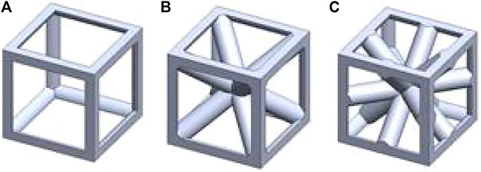
FIGURE 1. Geometrical sketch of designed unit structures. (A) cubic structure (B) cubic center (C) cubic edge center
The gradient porous implants are designed with a-b gradient structure with b as the core and a-c gradient structure with c as the core. The size of the gradient porous structure is 4 mm × 4 mm × 10 mm, of which the core structure is 2 mm × 2 mm × 10 mm. The overall cut is a gradient porous structure with a bottom diameter of 4 mm and a height of 10 mm. By adjusting the pillar radius of a, b, c lattice structure, the porosity and pore diameter of the implant can be adjusted. Figure 2 shows the model of a-b and a-c gradient porous structure cylinders. The inner and outer layer porosity, outer layer pore size and average porosity calculated by the gradient porous structure of the two combinations are shown in Table 1. The compressive performance test of the a-b structure gradient porous cylinder is performed, and the stress-strain curve is shown in Figure 3. The compressive specimens were manufactuer by the SLM-125 HL machine (Solutions Gmbh, Germany) under a Ar atmosphere contain below 0.02% oxygen. The laser power, laser scanning speed, layer thickness, and hatching distance were 200 W, 900 mm/s, 30 μm, and 0.14 mm. The compressive yield strength and elastic modulus values of each gradient porous structure column are calculated from the stress-strain curve, the results are shown in Figures 3A,B.
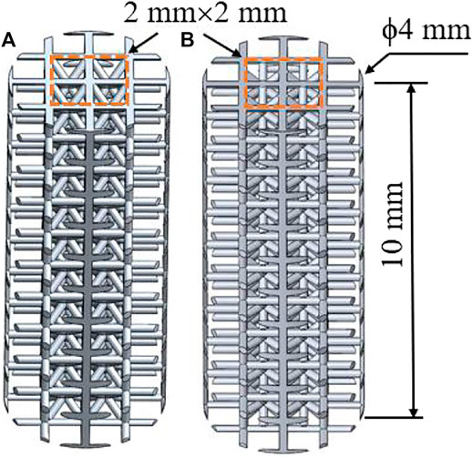
FIGURE 2. Model diagram of gradient porous structure column (A) a-b type structure (B) a-c type structure.
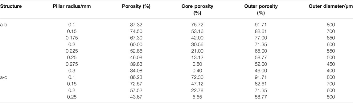
TABLE 1. Structural parameters of gradient porous structure model.
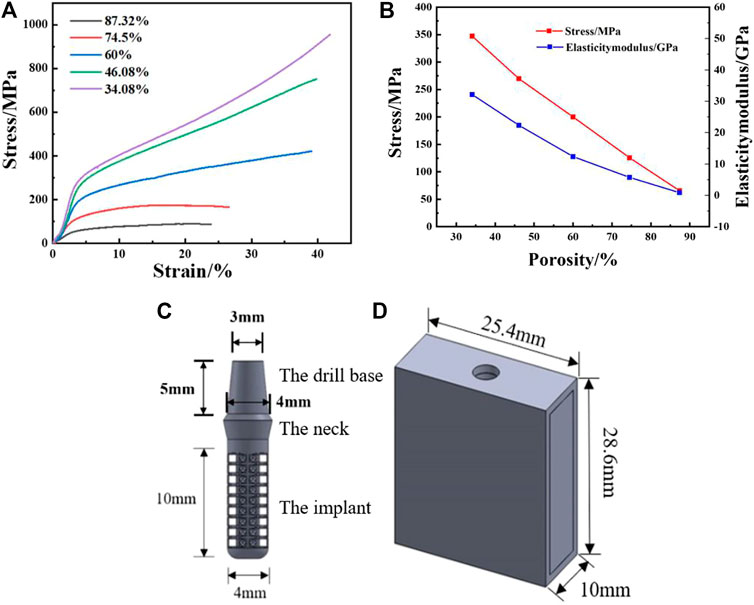
FIGURE 3. Actual measured value of SLM samples: (A) Compression yield strength, (B) Elasticity modulus; (C) Gradient porous dental implant mode, (D) Simplified mandible model.
Using Solidworks modeling software, the gradient porous implant model and the mandible model of the implant environment were constructed. Since the actual model of the human mandible is relatively complicated, the implant has a certain effect on the surrounding strong bone tissue when the implant is loaded. For the convenience of calculation, the constructed mandible model is a simple cuboid shape. 1) The implant body has a gradient porous structure with the length of 10 mm and the diameter of 4 mm; the neck height is 1.8 mm, the upper diameter is 4.8 mm, and the lower bottom diameter is 4 mm. A 5 mm high abutment is designed on the upper part of the implant. The top diameter of the abutment is 3 mm and the bottom diameter is 4 mm, which is simplified as a whole with the implant. 2) The simplified mandibular bone model has a total height of 28.6 mm, a mesiodistal length of 25.4 mm, a buccal-lingual length of 10 mm, and an outer cortical bone thickness of 1.3 mm, The thickness of the constructed cortical bone is close to that of the biological bone, and the total depth of the entire implant inserted into the mandible is 11.3 mm. The model is shown in Figures 3C,D.
Implant Static Analysis
The finite element analysis software used in this experiment is ANSYS Workbench 18.0. The basic parameters of the Ti material used are the characteristics obtained by the research team in the previous study: density 4.46 g‧cm−3, elastic modulus 110 GPa, compressive yield strength 607 MPa, tensile strength 894 MPa. Because the porous structure of this experiment is irregular, the method of freely dividing the grid is adopted by manually adjusting the grid accuracy, using a hexahedral grid with a size set to 0.5 mm. For the convenience of calculation, the lower surface is added as a fixed constraint, the bite force is 120 N, and the upper surface is applied vertically. The restraint and loading methods are shown in Figure 4. Each model contains 160 units.
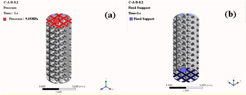
FIGURE 4. Compression simulation parameter settings (A) Load mode (B) Constraint conditions (a-b structure with porosity of 46.08% as an example).
Analysis of Biological Fit of Implants in Oral Environment
Material Parameter Setting
The use of three-dimensional finite element analysis for biomechanical analysis requires simplified processing of complex human tissues and materials. The implant material is titanium. The mandibular model is composed of cancellous bone and cortical bone. The relevant parameters of bone tissue and implant materials are shown in Table 2 (Santos et al., 2015).
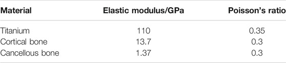
TABLE 2. Elastic modulus and Poisson’s ratio of bone tissue and implant material.
Contact Conditions and Constraints
The implant body and neck, implant neck and abutment, and cortical bone and cancellous bone are all set to be in binding contact. When analyzing the maximum equivalent stress and maximum equivalent strain of the bone tissue, it is assumed that complete osseointegration occurs between the implant and the surrounding bone, That is to simulate the changes in stress and strain at the end of planting. Therefore, the binding contact between the implant and the surrounding bone is set as a binding contact without sliding friction. When measuring the micro-movement of the implant-bone tissue interface, it is assumed that a fter the implant is stressed, there will be a pressing effect between the implant and the bone interface, and there will be a slight sliding along the interface, the friction coefficient is set to 0.3, That is, it simulates the micro-movement of the interface between the implant and the surrounding bone tissue at the early stage of implantation. In the simulation process, the buccal-lingual surface, mesiodistal surface, and bottom surface of the bone block model are set as rigid constraints, that is, it is assumed that the mandible does not move and does not shift. The setting of the above situation may have a certain error with the actual planting situation, but it has a certain guiding effect for the exploration of general rules. This is also to more conveniently and quickly find the best implant structure parameters.
Meshing
The implants in the oral environment are divided into tetrahedral meshes. The size of the grid will have a certain impact on the accuracy of the calculation result. The tighter the grid, the more accurate the result, but the larger the calculation amount. Therefore, dense grids are used for the implants and surrounding tissues. The rest uses a relatively loose grid. The 0.6 mm thickness of the implant-bone tissue interface adopts a dense grid, the grid size of this part is set to 0.3 mm, and the grid size of other parts is set to 0.5 mm, and the models of each group are consistent.
Loading Method
In this experiment, an average bite force of 120 N was used as the vertical load. At the same time, the combined force is set to simulate the limit bite force, which are 114.6 N in the axial direction, 17.1 N in the buccal and tongue direction, and 23.4 N in the proximal and distal directions. The combined force of the three directions is 15% with the long axis of the implant, and the size is 118.2 N. The two loading methods are shown in Figure 5.
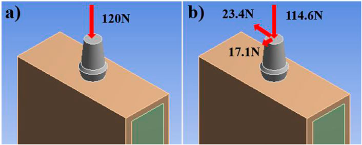
FIGURE 5. Load regime. (A) vertical loading (120 N) and (B) oblique loading (118.2 N).
Calculation Analysis and Observation Index
We usedse ANSYS Workbench software to perform static analysis on the model, obtain the stress and strain distribution cloud diagram of the implant and the bone tissue around the implant, calculate the stress dispersion of the implant and the cancellous bone, and analyze the distribution of the equivalent strain interval of the cancellous bone. The stress dispersion is defined as the ratio of the width of the stress distribution to the average stress. The smaller the dispersion, the more uniform the stress distribution. The definition formula of dispersion is shown in Eq. 1.
Where D represents the degree of dispersion, SMax is the maximum value of the stress or strain data, SMin is the minimum value of the data, and SSavr is the average value of the data.
The calculation of fretting is to define a node on the surface of the implant and determine the node at the corresponding position of the bone interface. After the loading force is applied, the relative displacement between the two nodes on the x-axis, y-axis and z-axis of the three-dimensional coordinate system is calculated. Therefore, when measuring implant micromotion, we took a reference point on the neck, body, and end of the implant, and measured the buccal-lingual (x-axis), vertical (y), and near-distal (z-axis) directions. The directional displacements are dx1, dy1, dz1, and the displacements of the corresponding points on the bone tissue interface are measured at the same time as dx2, dy2, dz2. According to Eq. 2, the comprehensive relative displacement, that is, the fretting value, is calculated:
Results and Discussion
The Effect of Structural Elements on the Mechanical Properties of Implants
The maximum equivalent stresses of the a-b structure and the a-c structure obtained by the axial force loading and compression simulation of the implant are shown in Figure 6. When the pillar radius of the two structures is 0.1°mm, the porosity is 87.32 and 86.23%, and the maximum equivalent stress is 948.3 and 940.2°MPa, respectively. The compressive yield strength of titanium is 607 MPa, therefore, yield occurs during use. When the pillar radius is the same, the overall porosity of the a-c structure is lower than that of the a-b structure, and the supporting area of the porous structure is larger, and the equivalent stress is smaller. But when the pillar radius is the same, the maximum equivalent stress of the a-b structure and the a-c structure is not much different, so the compressive performance of the two structures is basically the same.
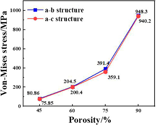
FIGURE 6. Maximum equivalent stress of two structures with different porosity.
The experiment further carried out simulation analysis for the a-b type structure with a small difference between the inner and outer layer structures. According to the principle of finite element analysis, the whole object is decomposed into finite structural elements, and the stress of each element is calculated, and the overall stress is obtained. The stress data of each cell in the model is derived, analogous to the calculation principle of the dispersion of particle size distribution, and the stress value of each element is analogous to the particle size, and the equivalent stress distribution is calculated. The result is shown in Figure 7. Overall, according to the obtained uniform stress distribution, under the action of axial force, as the porosity decreases, the effective bearing area of the force increases, and the stress distribution of the implant becomes more uniform; under the action of lateral force, the porosity is respectively 60.00, 52.86, 46.08% of the gradient structure and implants have good stress uniformity.
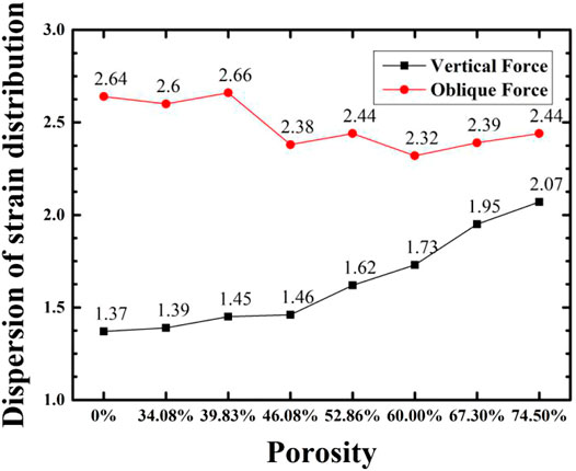
FIGURE 7. Variation of stress distribution of implant with porosity for implant with a-b gradient structure and compact structure.
The Effect of Porosity on the Mechanical Properties of Implants
Figure 8 shows the simulated maximum equivalent stress and theoretical yield strength of implants with different porosity gradient structures under two loads. The Compressive yield strength of the solid implant model is 607 MPa, and the finite element simulation results of the maximum equivalent stress under axial force and lateral force are 19.00 and 48.86 MPa, respectively, which are far lower than the yield strength of the material, and the compressive performance is optimum. In each group of gradient porous structure implants: under the action of axial force, as the porosity increases, the peak equivalent stress of the implant increases and the theoretical yield strength and compressive performance decrease. When the porosity is 74.50%, it cannot meet the mechanical performance requirements; when the porosity is less than 60.00% under lateral force, the maximum equivalent stress of the implant should be less than 50% of the yield strength to meet the requirements of stomatology for the mechanical performance of the implant. The minimum equivalent stress peak value of 46.08% implants is 96.33 MPa. Therefore, it is believed that the implants with 46.08% porosity have higher compressive strength and show better mechanical properties under lateral force.
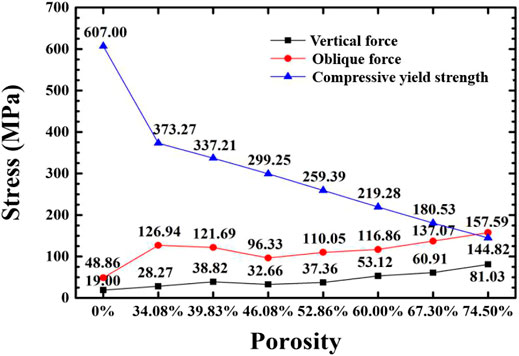
FIGURE 8. Variation of maximum equivalent stress and compressive yield strength of the implant with porosity under two loading regimes.
The Effect of Porosity on the Biological Fit of the Implant
According to the theory of bone mechanics, if the stress of bone tissue is less than 2 MPa (strain is less than 100 με), bone tissue will resorb; when the stress is in the range of 2–20 MPa (strain is in the range of 100–1,500 με), the bone tissue maintains normal bone quality and grows appropriately; when the stress is in the range of 20–60 MPa (strain is in the range of 1,500–3,000 με), it is in an active state of bone plastic construction; when the stress exceeds 60 MPa (strain exceeds 3,000 με), the bone tissue is in a pathologically over-loaded state, and a small load can cause a fracture. In addition, the micro-motion value of the implant-bone tissue should not exceed 50–100 μm in order to achieve the bone tissue surrounding the implant and good osseointegration. In the experiment, the critical value of bone tissue stress and the proportion within the interval were used as the analysis basis to evaluate the biocompatibility of implants with gradient structures with different porosities.
The bone tissue mainly in contact with the gradient structure of the implant is cancellous bone, and the bone tissue within 4.2 mm from the surface of the implant (Liu et al., 2019) is the main stress-affected area. Therefore, this part of the cancellous bone block was cut and observed. Under the action of axial force and oblique force, the implants with the porosity of 46.08 and 74.50%, and the surrounding bone tissue stress cloud diagrams are shown in Figures 9, 10, respectively. It can be seen from the stress cloud diagram that when the axial force is applied, the stress concentration of high-porosity implants is in the neck, and the stress concentration of low-porosity implants is around the body pores, which can reduce the tooth damage caused by excessive stress. When the lateral force is applied, the stress concentration of the implants of all structures appears in the neck.
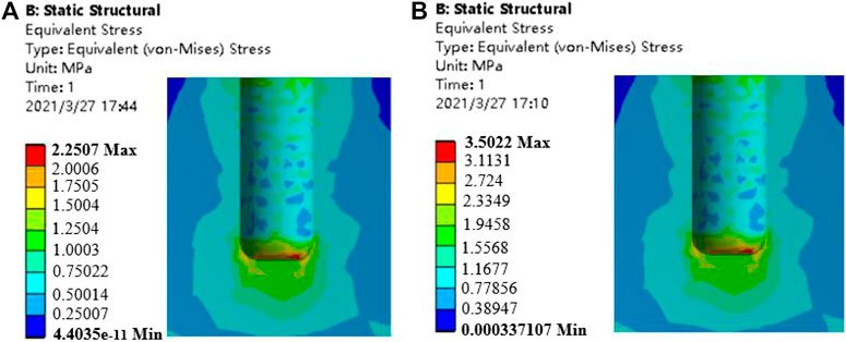
FIGURE 9. Stress nephrogram of cancellous bone under 120 N vertical loading. (A) porosity of 46.08% (B) porosity of 74.50%.
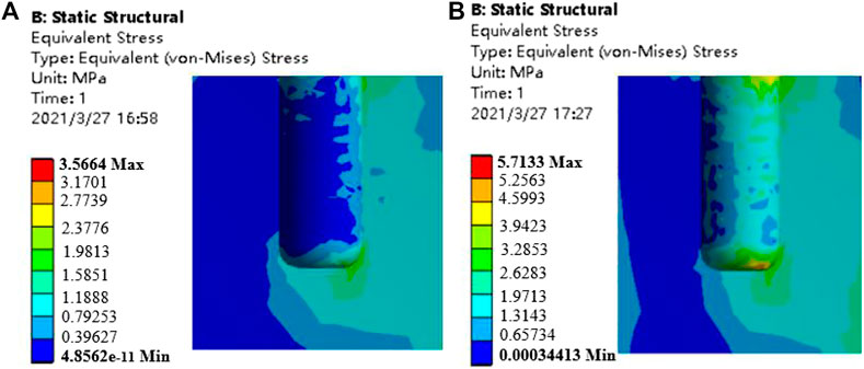
FIGURE 10. Stress nephrogram of cancellous bone under 118.2 N oblique loading (a) porosity of 46.08% b) porosity of 74.50%.
Figure 11 shows the comparison of the maximum equivalent stress and maximum equivalent strain of each group of gradient structure implant models and compact implant models. For compact implants, due to the stress shielding effect, the equivalent stress of the cancellous bone is lower than the normal growth value regardless of the axial force or the oblique force. When the porosity is lower than 39.83%, the maximum equivalent stress is lower than 2 MPa, which is the inactive mode threshold of bone tissue, and osteoblasts do not receive sufficient mechanical stimulation, resulting in disuse resorption of bone tissue. When the porosity is higher than 46.08%, and the maximum equivalent strain exceeds 3000 με of the bone repair micro-fatigue damage strain value, it results in pathological overload. The micro-fatigue damage accumulated in the bone in these areas can easily cause pathological fractures. The porosity of the gradient structure implant is in the range of 39.83–46.08%, which can meet the normal growth of bone tissue.
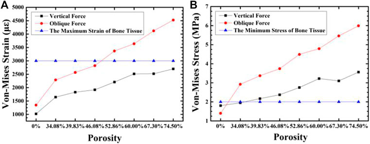
FIGURE 11. The variation of maximum equivalent strain (A) and stress (B) in the cancellous bone around the implant with the porosity of the implant.
When the strain of the bone tissue is 100–1,500 με, the existing surrounding bone tissue can be maintained to prevent bone loss, and when the strain is high, it is conducive to the formation of bone (Liu et al., 2019). For the cancellous bone within 100–1,500 με, we plotted the frequency histogram of the strain data and calculated the average equivalent strain, the porosity of the gradient structure implants with 46.08 and 74.50%, and the strain distribution of cancellous bone around the dense structure implant. As shown in Figures 12, 13, as the porosity decreases, the strain distribution width decreases, the peak value increases, and the strain distribution in the bone tissue become more uniform. The comparison of the average equivalent strain results of each group of gradient structure implants is shown in Figure 14. According to the statistical results, under the action of axial force, the larger average equivalent strain is the implant with porosity 39.83 and 46.08%; under the action of lateral force, the larger average equivalent strain is the porosity 39.83 and 46.08% and 52.86% of implants. The larger the average equivalent strain, the greater the strain on the whole cancellous bone, which is considered to be closer to the range of active reconstruction of bone tissue and beneficial to bone formation. In the two loading modes, the average equivalent strain of the implants with the porosity of 39.83 and 46.08% is larger, which is more conducive to bone formation.
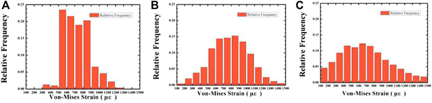
FIGURE 12. The variation of the relative frequency with Von-mizes strain in the cancellous bone under 120 N vertical loading. Average porosity: (A) 0% (compact structure); (B) 46.08%; (C) 74.50%.
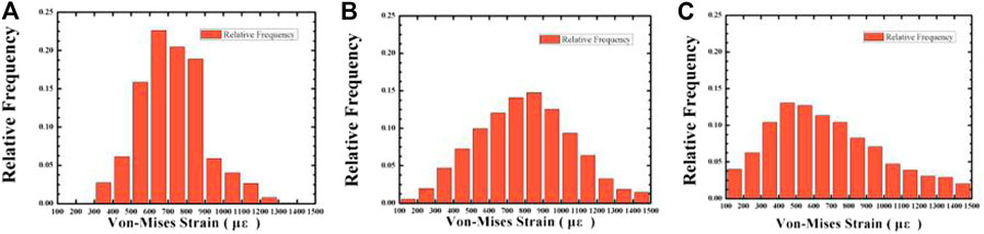
FIGURE 13. The variation of the relative frequency with Von-mizes strain in the cancellous bone under 118.2 N oblique loading. Average porosity: (A) 0% (compact structure); (B) 46.08%; (C) 74.50%.
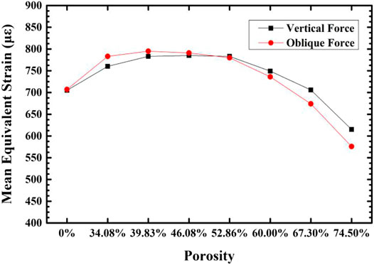
FIGURE 14. The variation of equivalent strain in the cancellous bone around implants with porosity.
When the strain of bone tissue is in the range of 1,500–3,000 με, the rate of bone formation is faster than that of bone resorption, and lamellar bone formed on the bone surface. The proportion of unit cells that have an equivalent strain in the range of 1,500–3,000 με in the cancellous bone around the implant under two loading regimes are calculated, and are shown in Figure 15. It can be seen that with the porosity increase, the proportion of cells with an equivalent strain in the range of 1,500–3,000 με increases, that is, there are more bone tissues in an active bone-forming state, and the quantitative binding capacity increases. Compared with the porosity of 39.83%, when the porosity is 46.08%, there are more unit cells in the surrounding cancellous bone for active bone formation.
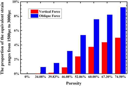
FIGURE 15. The variation of the proportion of cancellous bone around the implant that have strain in the range of 1,500–3,000°με with the porosity of the implant.
The optimal gradient structure implant in this experiment was compared with the gradient structure implant [23] that has been studied. The comparison results are shown in Table 3. It can be seen that the pore parameters of the two structures are basically the same. In vivo, animal experiments were carried out in the research of Wang Yaling[23], and it was concluded that the designed gradient structure implant has good osseointegration performance. The maximum equivalent stress of the bone tissue in this experiment is similar to the results[23]. It can be seen that the best gradient structure implant obtained in this experiment also has considerable osseointegration capacity. This experiment adopts a gradient lattice structure, compared with the gradient structure obtained by directly opening the holes in the reference, it is also a side load stress. The maximum equivalent stress of the optimal gradient structure implant obtained in this experiment is 96.33 MPa. The proposity of structure in this study is lower than the design of the Wang Yaling, and it is not easy to break. In addition, the compression strength of the implant in the work of Wang Yaling (Wang, 2017) is 259.39 MPa, while the compression strength of the implant in this experiment is 299.25 MPa.
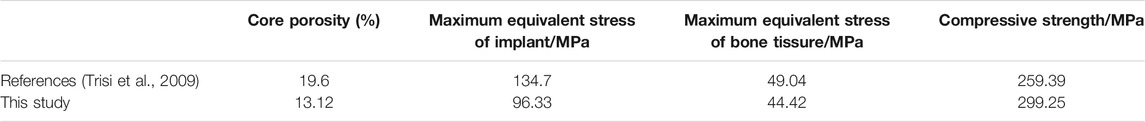
TABLE 3. The optimal gradient structure implant in this study and in other’s study.
Gradient Structure Implant-Bone Tissue Section Micro-movement
The initial stability of the implant means that in the initial stage of implantation into the bone tissue, the implant will not have a large relative displacement between the interface and the bone tissue due to external force. The small mobility between the implant and the bone interface in the early stage of implantation is not conducive to the adhesion of osteoblasts around the implant. It will also repeatedly interfere with the normal bone reconstruction process, reduce the osseointegration effect, and affect the area that has reached healing and causes damage. The calculation of fretting is to define a node on the surface of the implant and determine the node at the corresponding position of the bone interface. After the loading force is applied, the relative displacement between the two nodes on the x-axis, y-axis and z-axis of the three-dimensional coordinate system is calculated. This experiment calculated the micro-movements of the implant-cortical bone interface, the implant-cancellous bone (top) interface, and the implant-cancellous bone (bottom) interface in each group of implant models. For the implant-bone tissue in each group, the fretting value of the interface is between 6.63 and 22.53 µm. It is generally believed that the fretting value of the implant-bone tissue should not exceed 50–100 µm to achieve the bone tissue surrounding the implant instead of fibrous tissue surrounding the implant. Therefore, the micro-movement of the implant-bone tissue interface of each gradient structure does not exceed 50 μm, and it has the ability to complete osseointegration.
Conclusion
1) As the porosity decreases, the compressive strength of the gradient porous implant increases. For the a-b structure with a porosity of 46.08%, the maximum equivalent stress is the lowest under the lateral force environment, and the stress distribution is uniform.
2) With the increase of porosity, the maximum equivalent stress and maximum equivalent strain in the bone tissue increase. When the porosity of the implant is 39.83–46.08%, the stress and strain of the bone tissue are in the range that satisfies normal growth. As the porosity decreases, the average equivalent strain of cancellous bone first increases and then decreases, and the proportion of strain decreases in the range of 1,500–3,000 με. Under the action of axial force, the stress distribution in the cancellous bone becomes more uniform as the porosity decreases; under the action of lateral force, the stress distribution in the cancellous bone becomes more even when the porosity is higher.
3) The best gradient porous structure parameters were: average porosity 46.08%, inner porosity 13.12%, outer porosity 58.77%, outer pore size 500 um. Under this structure, the equivalent strain is in a suitable range for the active bone growth and integration. The maximum equivalent stress under the oral ultimate stress is 99.33 MPa, much lower than the yield strength of 269.72 MPa.
Data Availability Statement
The original contributions presented in the study are included in the article/supplementary material, further inquiries can be directed to the corresponding authors.
Author Contributions
Paper Write: BL; Funding Administration: XL, CL; Paper Revised: WX, MT, JD; Experiment: BL, MC, YL; Thesis guidance: XQ, XH, JZ, LG.
Funding
This research work is supported by the National Natural Science Foundation of China (51922004, 51874037), State Key Lab of Advanced Metals and Materials, University of Science and Technology Beijing (2019-Z14,2020Z-04), Fundamental Research Funds for the Central Universities (FRF-TP-19005C1Z), European Union via H2020-MSCA-RISE program (BAMOS project, grant no: 734156) and Royal Society via International Exchange Programme (grant no: IEC\NSFC\191253). WX acknowledges the support from the China Scholarship Council (CSC) for a CSC Ph.D. scholarship (201906460106). Engineering and Physical Science Research Council (EPSRC) via DTP CASE programme (Grant No: EP/ T517793/1).
Conflict of Interest
The authors declare that the research was conducted in the absence of any commercial or financial relationships that could be construed as a potential conflict of interest.
References
Brunski, J. B., Puleo, D. A., and Nanci, A. (2000). Biomaterials and Biomechanics of Oral and Maxillofacial Implants: Current Status and Future Developments. Int. J. Oral Maxillofac. Implants 15 (1), 15–46. doi:10.1046/j.1365-2591.2000.00269.x
Carpenter, R. D., Klosterhoff, B. S., Torstrick, F. B., Foley, K. T., Burkus, J. K., Lee, C. S. D., et al. (2018). Effect of Porous Orthopaedic Implant Material and Structure on Load Sharing with Simulated Bone Ingrowth: A Finite Element Analysis Comparing Titanium and PEEK. J. Mech. Behav. Biomed. Mater. 80, 68–76. doi:10.1016/j.jmbbm.2018.01.017
Chen, S. Y., Huang, J. C., Pan, C. T., Lin, C. H., Yang, T. L., Huang, Y. S., et al. (2017). Microstructure and Mechanical Properties of Open-Cell Porous Ti-6Al-4V Fabricated by Selective Laser Melting. J. Alloys Compounds 713 (8), 248–254. doi:10.1016/j.jallcom.2017.04.190
Chia, H. N., and Wu, B. M. (2015). Recent Advances in 3D Printing of Biomaterials. J. Biol. Eng. 9 (1), 1–14. doi:10.1186/s13036-015-0001-4
Forst, H. M. (2004). A 2003 Update of Bone Physiology and Wolff's Law for Clinicians. Angle Orthodontist 74 (1), 3–15. doi:10.1043/0003-3219(2004)0742.0.CO;2
He, G., Liu, P., and Tan, Q. (2012). Porous Titanium Materials with Entangled Wire Structure for Load-Bearing Biomedical Applications. J. Mech. Behav. Biomed. Mater. 5 (1), 16–31. doi:10.1016/j.jmbbm.2011.09.016
Jiang, G., Li, Q., Wang, C., Dong, J., and He, G. (2015). Fabrication of Graded Porous Titanium-Magnesium Composite for Load-Bearing Biomedicalapplications. Mater. Des. 67 (2), 354–359. doi:10.1016/j.matdes.2014.12.001
Lee, H., Park, S., and Noh, G. (2019). Biomechanical Analysis of 4 Types of Short Dental Implants in a Resorbed Mandible. The J. Prosthetic Dentistry 121 (4), 659–670. doi:10.1016/j.prosdent.2018.07.013
Lewis, G. (2013). Properties of Open-Cell Porous Metals and Alloys for Orthopaedic Applications. J. Mater. Sci. Mater. Med. 24 (10), 2293–2325. doi:10.1007/s10856-013-4998-y
Liu, F., Zhang, D., Zhang, P., Zhao, M., and Jafar, S. (2018). Mechanical Properties of Optimized Diamond Lattice Structure for Bone Scaffolds Fabricated via Selective Laser Melting. Materials 11 (3), 374–391. doi:10.3390/ma11030374
Liu, L., Duan, J., Shi, Q., Chen, Q., Yao, Q., and Li, Z. (2020). Mechanical Effect on the Evolution of Bone Formation during Bone Ingrowth into a 3D-Printed Ti-alloy Scaffold. Mater. Lett. 273, 127921. doi:10.1016/j.matlet.2020.127921
Liu, L., Shi, Q., Chen, Q., and Li, Z. (2019). Mathematical Modeling of Bone In-Growth into Undegradable Porous Periodic Scaffolds under Mechanical Stimulus. J. Tissue Eng. 10, 204173141982716. doi:10.1177/2041731419827167
Roy, S., Dey, S., Khutia, N., Roy Chowdhury, A., and Datta, S. (2018). Design of Patient Specific Dental Implant Using FE Analysis and Computational Intelligence Techniques. Appl. Soft Comput. 65 (1), 272–279. doi:10.1016/j.asoc.2018.01.025
San, C. V., Paul, F., Aadil, M., Melanie, J. C., and Gordon, W. B. (2018). Novel Adaptive Finite Element Algorithms to Predict Bone Ingrowth in Additive Manufactured Porous Implants. J. Mech. Behav. Biomed. Mater. 87, 230–239. doi:10.1016/j.jmbbm.2018.07.019
Santos, L. S. d. M., Rossi, A. C., Freire, A. R., Matoso, R. I., Caria, P. H. F., and Prado, F. B. (2015). Finite-Element Analysis of 3 Situations of Trauma in the Human Edentulous Mandible. J. Oral Maxillofacial Surg. 73 (4), 683–691. doi:10.1016/j.joms.2014.10.014
Tane, M., Hagihara, K., Ueda, M., Nakano, T., and Okuda, Y. (2016). Elastic-modulus Enhancement during Room-Temperature Aging and its Suppression in Metastable Ti-Nb-Based Alloys with Low Body-Centered Cubic Phase Stability. Acta Materialia 102 (1), 373–384. doi:10.1016/j.actamat.2015.09.030
Taniguchi, N., Fujibayashi, S., Takemoto, M., Sasaki, K., Otsuki, B., Nakamura, T., et al. (2016). Effect of Pore Size on Bone Ingrowth into Porous Titanium Implants Fabricated by Additive Manufacturing: An In Vivo experiment. Mater. Sci. Eng. C 59 (2), 690–701. doi:10.1016/j.msec.2015.10.069
Trisi, P., Perfetti, G., Baldoni, E., Berardi, D., Colagiovanni, M., and Scogna, G. (2009). Implant Micromotion Is Related to Peak Insertion Torque and Bone Density. Clin. Oral Implants Res. 20 (5), 467–471. doi:10.1111/j.1600-0501.2008.01679.x
Wally, Z. J., Haque, A. M., Feteira, A., Claeyssens, F., Goodall, R., and Reilly, G. C. (2019). Selective Laser Melting Processed Ti6Al4V Lattices with Graded Porosities for Dental Applications. J. Mech. Behav. Biomed. Mater. 90 (8), 20–29. doi:10.1016/j.jmbbm.2018.08.047
Wang, Yaling. (2017). Research on the Performance of Porous Structure Implants Based on Laser Selective Melting technology[D]. PhD Thesis. Chongqing, China. Chongqing University.
Weissmann, V., Bader, R., Hansmann, H., and Laufer, N. (2016). Influence of the Structural Orientation on the Mechanical Properties of Selective Laser Melted Ti6Al4V Open-Porous Scaffolds. Mater. Des. 95 (4), 188–197. doi:10.1016/j.matdes.2016.01.095
Keywords: titanium, gradient porosity, oral implants, three-dimensional finite element simulation, bone stress
Citation: Liu B, Xu W, Lu X, Tamaddon M, Chen M, Dong J, Liu Y, Guo L, Zhang J, Qu X, He X and Liu C (2021) The Optimization of Ti Gradient Porous Structure Involves the Finite Element Simulation Analysis. Front. Mater. 8:642135. doi: 10.3389/fmats.2021.642135
Received: 15 December 2020; Accepted: 08 June 2021;
Published: 21 June 2021.
Edited by:
Bing Han, Peking University School and Hospital of Stomatology, ChinaReviewed by:
Qiang Chen, Southeast University, ChinaSarabjeet Singh Sidhu, Beant College of Engineering and Technology, India
Copyright © 2021 Liu, Xu, Lu, Tamaddon, Chen, Dong, Liu, Guo, Zhang, Qu, He and Liu. This is an open-access article distributed under the terms of the Creative Commons Attribution License (CC BY). The use, distribution or reproduction in other forums is permitted, provided the original author(s) and the copyright owner(s) are credited and that the original publication in this journal is cited, in accordance with accepted academic practice. No use, distribution or reproduction is permitted which does not comply with these terms.
*Correspondence: Xin Lu, bHV4aW5AdXN0Yi5lZHUuY24=; Chaozong Liu, Y2hhb3pvbmcubGl1QHVjbC5hYy51aw==