 Bochao Wang
 Tao Hu1
 Leif Kari
 Xinglong Gong
- 1Chinese Academy of Sciences (CAS) Key Laboratory of Mechanical Behavior and Design of Materials, Chinese Academy of Sciences (CAS) Center for Excellence in Complex System Mechanics, Department of Modern Mechanics, University of Science and Technology of China, Hefei, China
- 2Hunan Bogie Engineering Research Center, Zhuzhou, China
- 3Anhui Weiwei Rubber Parts Group Co. Ltd., Tongcheng, China
- 4CAS Key Laboratory of On-orbit Manufacturing and Integration for Space Optics System, Changchun Institute of Optics, Fine Mechanics and Physics, Chinese Academy of Sciences, Changchun, China
- 5KTH Royal Institute of Technology, Department of Engineering Mechanics, The Marcus Wallenberg Laboratory for Sound and Vibration Research (MWL), Stockholm, Sweden
The application of magneto-sensitive (MS) rubber in a vehicle vibration control area is likely to be expected. This conclusion is based on the following two reasons: the maturity of fabrication of MS rubber which meets the application requirement and the feasibility of the constitutive model of MS rubber that accurately reflects its mechanical performance. Compared with the traditional rubber, small ferromagnetic particles are embedded in the elastomer of MS rubber, leading to a change of mechanical properties when an external magnetic field is applied. Therefore, devices with MS rubber, can be viewed as a semi-active actuator. In this study, MS rubber with a relative high increase in the magneto-induced modulus is fabricated and characterized. Furthermore, a one-dimensional constitutive model to depict the magnetic field-, frequency-, and strain amplitude-dependent dynamic modulus of MS rubber is applied. Finally, simulations of a MS rubber semi-active suspension under a bump and a random ground excitation with different control strategies on a quarter vehicle model are conducted to illustrate the feasibility of the MS rubber in the vehicle vibration control application context.
1. Introduction
The performance of vehicle suspensions is closely related to the automotive noise, vibration, and harshness (NVH) issue (Heißing and Ersoy, 2011). In order to improve the ride comfort and the road holding ability and to reduce suspension deflection, three types of suspensions, namely, passive, active, and semi-active, are utilized. The passive suspension has the advantage of cost-effectiveness and design simplicity. However, its stiffness cannot be adjusted according to the external loadings. Therefore, the performance of the passive suspension is limited. Regarding the active suspension, it can exert control force independently without relying on the structural response, which makes it effective to reduce vibration. Nevertheless, its high cost, design complexity, and the lack of stability when the power input is cut off under extreme conditions prohibit its practical application (Martins et al., 1999). The recent progress in smart material development makes the semi-active vehicle suspension to have a superior suspension measure. In particular, desired vibration-reduction performance is more likely to be achieved by semi-active suspensions, compared to the results using passive suspensions. Furthermore, less energy is consumed by semi-active suspensions when compared with active ones. In the past few years, magneto rheological (MR) fluid (MRF) (Zhang et al., 2004; Biglarbegian et al., 2008; Wilson and Abdullah, 2010; Phu and Choi, 2019; Du et al., 2020) was widely used in the semi-active control area due to its rapid response, temperature insensitivity of the mechanical property, and its high MR effect. However, it is worth noting that although the motion of the suspension can hinder the settlement of ferromagnetic particles in MRF, the increased zero-field viscosity due to the wear of ferromagnetic particles after a long-term operation will reduce the vibration control effect of MRF suspensions (Hu et al., 2012). For magneto-sensitive (MS) rubber, ferromagnetic particles are fixed in the elastomer matrix, thus avoiding the problem of ferromagnetic particle wear and material leakage (Bastola et al., 2019). Therefore, semi-active suspensions based on MS rubber provide a feasible and practical solution to the vibration control problem for vehicles.
The research of MS rubber can be divided into three categories, including fabrication optimization to improve the mechanical property, constitutive modeling of MS rubber, and exploring of possible applications of MS rubber. Davis (1999) analyzed that the optimum particle volume fraction for MS rubber to achieve the highest magnetic modulus is 27%. This conclusion was verified experimentally by Lokander and Stenberg (2003) and Zhou (2003). Subsequently, the influence of the matrix type (Shen et al., 2004), coupling agent (Chen et al., 2007a), pre-structuring (Li et al., 2008), and the surface modification (Jiang et al., 2008) of particles on the MR effect and damping property of MS rubber were investigated. Tong et al. (2018) fabricated a kind of MS rubber with an improved field-induced storage modulus by mixing flow-like particles into the elastomer matrix. It can be foreseen that it will be possible to fabricate MS rubber with a good mechanical performance and a high relative MR effect to meet the engineering application needs, due to the rapid development of MS rubber, including the optimization of their manufacturing process.
In order to predict the mechanical performance of MS rubber, constitutive models with strain and magnetic field strength as inputs and stress as output are needed. Initially, Jolly et al. (1996) developed a magnetic dipole model to simulate the shear modulus increase of MS rubber under a magnetic field. The dipole model was further extended by taking the viscoelastic behavior of MS rubber (Chen et al., 2007b), the interaction of multi-chains (Zhu et al., 2006), and the distribution (Zhang et al., 2010) of chain angles into account. In parallel, constitutive models based on the rheological theory were developed to depict the magnetic field-related non-linear viscoelastic behavior of MS rubber (Li et al., 2010; Chen and Jerrams, 2011). Wang et al. (2018) developed a constitutive modeling-electromagnetic analysis combining method to describe the mechanical behavior of MS rubber. By using the methods mentioned, the mechanical behavior of MS rubber under a small deformation can be predicted accurately. In order to predict the mechanical performance of MS rubber under a large deformation, Dorfmann and Ogden (2003) as well as Kankanala and Triantafyllidis (2004) derived the fundamental balance principles of magneto-elastic materials based on the continuum mechanical theory. Subsequently, the continuum mechanical-based model was further expanded to include the viscoelasticity (Saxena et al., 2014), anisotropy (Bustamante, 2010; Danas et al., 2012), and the strain amplitude-dependent non-linear behavior of MS rubber (Wang and Kari, 2020). Based on the work of Kankanala and Triantafyllidis (2004) and Zhao et al. (2019) developed a model for hard-magnetic particle-based MS rubber. However, for the application of MS rubber in the field of semi-active vibration control, normally, the required force and structural responses are known values where the magnetic field required to achieve the control force needs to be calculated. Accordingly, an inverse model with stress and strain as inputs and the magnetic field strength as output is needed. Current research (Jung et al., 2011; Yang et al., 2016; Wang and Kari, 2019) showed that a better vibration reduction effect can be achieved by MS rubber-based devices, as compared to the traditional passive ones, by controlling the stiffness of MS rubber-based devices discontinuously through switching the magnetic field between zero and saturation state (on-off control). Compared with the on-off control strategy, the development of the inverse model makes the continuous adjustment of the stiffness of the MS rubber-based device a reality. Therefore, it can be foreseen that a semi-active control strategy based on the inverse model of MS rubber can achieve an even better vibration control effect than the previously mentioned on-off control strategy.
To explore the application of MS rubber, Liao et al. (2013) and Sun et al. (2018) designed MS rubber vibration absorbers with the function of tracking external excitation frequency and verified the vibration control effect experimentally. Wang et al. (2017) designed a conical shaped MS rubber-tuned mass damper with an improved stiffness changing ability. Blom and Kari (2012) designed an MS rubber bushing and demonstrated that an optimal isolation effect can be obtained by changing the magnetic field under different frequencies. Subsequently, Alberdi-Muniain et al. (2012, 2013) verified the previous conclusion experimentally. Wang and Kari (2019) simulated the vibration control effect of a MS rubber isolator under a random loading case by using a fuzzy logical control algorithm. Jin et al. (2020) explored the possible application of MS rubber in high-speed railway vehicles. Fu et al. (2019) investigated the design method of an adaptive fuzzy controller for a MS rubber vibration isolator under time-varying sinusoidal excitation. In the field of automobile suspension, Du et al. (2011) deduced the design method of the control gain of the MS rubber semi-active seat suspension H-infinity controller under the conditions of stiffness saturation and parameter uncertainty. Liu et al. (2020) used an adaptive neutral network control design method to simulate the control effect of the MS rubber-based seat isolator under a bump and a random road excitation. However, the magnetic field-dependent non-linear viscoelastic behavior of MS rubber has not been fully taken into account. Meanwhile, Liu et al. (2020) applied a polynomial expansion fitting method to determine the relationship between the shear modulus of the MS rubber isolator and the magnetic field strength. However, the method is only suitable for some specific working conditions which is difficult to extend directly to practical application situations.
In this study, a silicone rubber-based MS rubber with a relatively high MR effect is fabricated and characterized on a commercial rheometer. Subsequently, a constitutive model which depicts the magnetic field-dependent non-linear viscoelastic behavior of MS rubber is applied to depict the mechanical performance of MS rubber. Furthermore, an inverse model based on the constitutive model of MS rubber with stress and strain as input and the magnetic field strength as output is proposed. On the basis of the constitutive and inverse model, the H-infinity control strategy is used to simulate the vibration control effect of the MS rubber-based vehicle suspension under a bump and a random road excitation.
The research in this study includes material fabrication, characterization, forward and inverse modeling, and simulation analysis, covering a broad application range for MS rubber in vibration control area. The research performed in this article is meaningful for advancing the application of MS rubber in the vehicle suspension area. Furthermore, the forward constitutive model and the inverse model proposed can also be used in other semi-active control scenarios.
2. Characterization and Constitutive Modeling of MS Rubber
2.1. Material Fabrication and Characterization
The MS rubber sample in this study was fabricated by mixing silicon rubber (type multi-purpose silicone sealant, Selleys Pty Ltd., Australia), silicon fluid (XIAMETER PMX-200, Dow Corning GmbH, United States), and carbonyl iron particles (CIPs, type CN, BASF, Germany diameter 7 μm on average) with a mass fraction ratio of 2:1:7 at room temperature. After mixing for 5 min, the mixture was placed in a vacuum chamber with a pressure of 0.06 MPa for 10 min to remove air bubbles. Subsequently, the mixture was put into a mold under a magnetic field strength of 1 T for 30 min. After the CIPs were chained, the mixture was left for 48 h at room temperature for post-curing. The images of the MS rubber sample under the scanning electron microscope (Gemini 500, Carl Zeiss, Jena, Germany) at different magnification rates are in Figure 1, where arrows represent the chain direction of the iron particles. It can be seen that most iron particles are distributed along the chain direction in the matrix and that there is no large-scale clustering of the iron particles.
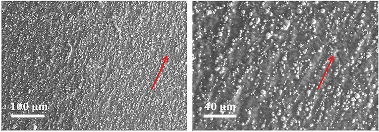
Figure 1. Scanning electron microscope image of MS rubber sample.
After MS rubber was fabricated, the sample with a diameter of 20 mm and a thickness of 2.12 mm were put into a commercial rheometer (Physica MCR 301, Anton Paar Co., Austria) to test the dynamic performance of MS rubber. The test was performed at room temperature 22 ± 1 °C. Throughout the test, the external magnetic field was parallel to the iron particle chain direction, while the twist direction of the commercial rheometer was perpendicular to the chain direction. During the measurement, three kinds of conditions were altered: strain amplitude (1, 2, and 5%), magnetic field strength (0, 0.17, 0.34, 0.51, 0.68, and 0.83 T), and frequency (1, 2, 5, 10, 20, 30, 40, 50, 60, 70, and 80 Hz). All combinations of the above three types of conditions were measured, recorded, and averaged over 20 periods. In order to avoid the influence of the Mullins effect (Mullins, 1969), a repeated shear strain where the strain amplitude is slightly larger than the maximum test shear strain was applied before the measurements started. The repeated preloading was terminated when the test results of two consecutive cycles are the same.
Test results for the magnitude and loss factor of the shear modulus vs. frequency with different strain amplitudes and magnetic field strengths are shown in the dot symbols in Figures 2–4. Similar to the measurement result by Blom and Kari (2005), the measured shear modulus of MS rubber shows a magnetic field, frequency, and strain amplitude dependence. Specifically, a higher frequency, a stronger magnetic field strength, and a lower strain amplitude led to an increased shear modulus magnitude, while the loss factor almost keeps constant under different frequencies, magnetic field strengths, and strain amplitudes. Furthermore, it can be found that the increasing rate of the shear modulus magnitude, with respect to the increasing magnetic field strength, slows down gradually until a magnetic saturation is reached for the material. Although the shear modulus magnitude of MS rubber seems to increase after 0.83 T, the upper limit of the magnetic field strength in the test was nevertheless set to be 0.83 T due to the sharp rise of the test object temperature that is generated by even stronger magnetic fields.
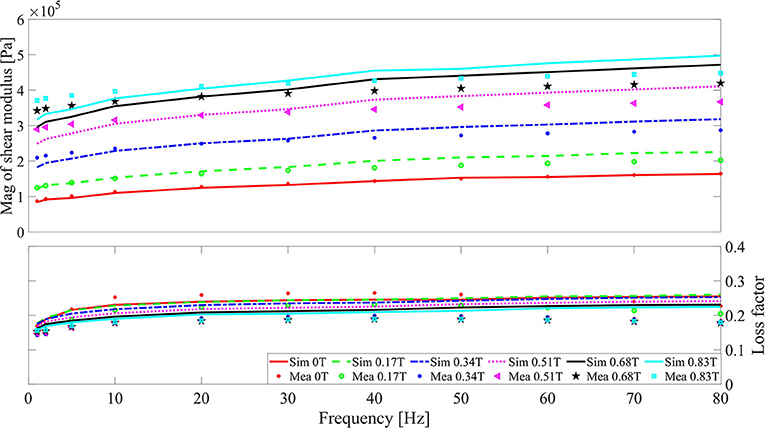
Figure 2. Shear modulus magnitude and loss factor of MS rubber vs. frequency with 1% strain. Lines and symbols are the simulation and experiment results, respectively.
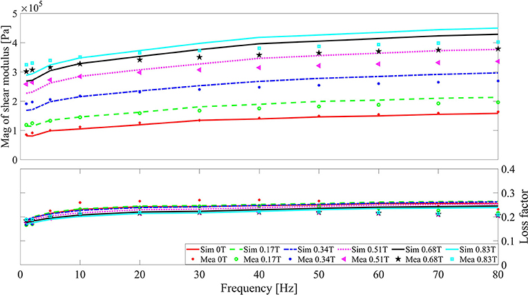
Figure 3. Shear modulus magnitude and loss factor of MS rubber vs. frequency with 2% strain. Lines and symbols are the simulation and experiment results, respectively.
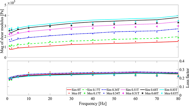
Figure 4. Shear modulus magnitude and loss factor of MS rubber vs. frequency with 5% strain. Lines and symbols are the simulation and experiment results, respectively.
2.2. Constitutive Modeling
An elastic spring with a parameter μe, a viscoelastic element with parameters a and b, and a frictional element with parameters τfmax and γ1/2 in parallel are used to depict the dynamic mechanical behavior of MS rubber. Initially, a fractional derivative viscoelastic element is utilized to depict the frequency-dependent shear modulus of MS rubber and to simplify the parameter identification. The relation between the viscoelastic stress τve and strain γ for the fractional derivative element in frequency domain is
where represents the Fourier transform, j is the imaginary unit, and ω is the angular frequency. From Equation (1), it can be observed that the modulus magnitude bωa increases with increasing frequency and the loss factor tan(aπ/2) is a constant value for the fractional derivative element. For more details regarding the fractional derivative model, please refer to Lubich (1986), Lion and Kardelky (2004), and Kari (2017, 2020).
In order to simulate the strain amplitude dependence of the shear modulus of MS rubber, a smooth frictional stress model is used (Berg, 1998). The relation between the friction stress (τf) and strain γ is
where τfmax and γ1/2 are model parameters, representing the maximum friction stress and the strain where one half of τfmax is reached and represents the strain rate. Initially, τfs = 0 and γs = 0. When the loading direction is changed, τfmax and γ1/2 are updated (if , and ). For more details regarding the smooth frictional stress model, the reader is referred to Berg (1998). By Equations (1) and (2), the total dynamic modulus G* in frequency domain is
After establishing the basic frame of the constitutive model, a non-linear least square fit method is implemented to obtain the basic material parameters by using the measurement results at zero magnetic field. The function lsqnonlin in MATLAB® (MATLAB Release 2015b, The MathWorks, Inc., Natick, Massachusetts, United States) is utilized for parameter identification. In the process of parameter identification, the objective function is set as
where and are the measured and simulated shear modulus of MS rubber, respectively. The symbol i represents the number of loading cases ranging from 1 to 33 since there are 3 kinds of strain amplitude and 11 kinds of frequency during the test under zero magnetic field. The identified material parameters are , a = 0.2071, b = 3.4587 × 10⁴ N sa m−2, , and , where symbols with a superscript zero represent the material parameters at zero magnetic field.
Compared with the generalized Maxwell model, less material parameters are needed for the fractional derivative element to depict the viscoelastic behavior of rubber materials (Haupt and Lion, 2002). Thus, the material parameters are easier to identify for the fractional derivative element. The solution of the viscoelastic stress of the fractional derivative model at the current time step τve (nΔt) in time domain is
where c1(α) = 1, cj(α) = (j − 1 − α) cj−1(α)/j and Δt is the time interval for the numerical implementation. As a comparison, the solution of the viscoelastic stress of the Maxwell element at the current time step (Simo and Hughes, 2006) is
where G and η are the modulus and the relaxation time of the Maxwell model, respectively. The equivalence of Equation (6) in frequency domain (Serra-Aguila et al., 2019) is
By comparing Equations (5) and (6), it can be seen that in order to obtain the viscoelastic stress at the current time step, only stress and strain data at the previous time step are needed for the Maxwell model. However, data of all strain history are needed to obtain the current viscoelastic stress for the fractional derivative element. Therefore, for numerical implementation concern, the Maxwell model is more effective than the fractional derivative element as the time step increases. Taking into account the need for the subsequent time domain simulation, three Maxwell models in parallel are used to substitute the previous fractional derivative model. The identified parameters and are fixed for the second round of parameter identification. The new material parameters identified are , , , , , , and with a relative error between the measurement and simulation result of 2.769%. The comparison between the measurement and simulation results are in Figure 5.
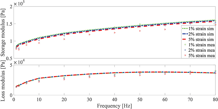
Figure 5. Shear modulus magnitude and loss factor of MS rubber vs. frequency under zero magnetic field. Lines and symbols are the simulation and experiment results, respectively. Three kinds of strain (1, 2, and 5%) are considered.
After modeling the frequency and the strain amplitude dependence, the magnetic field dependence of the shear modulus of MS rubber depicted by a hyperbolic tangent function is included in the constitutive model. According to Berg (1998), the area of the hysteresis loop for the smooth frictional stress model increases with increasing τfmax and decreasing γ1/2. Following the path of Blom and Kari (2011), the magnetic field dependence is included in τfmax and γ1/2 by
and
where Bs is a material parameter used to reflect the magnetic saturation behavior of MS rubber and δ1 and δ2 are parameters to reflect the magnetic enhancement of MS rubber. To guarantee that the loss factor is a relatively constant value with respect to the magnetic field strength, the hyperbolic tangent function is included into the elastic part as well
where the meaning of δ3 is similar to δ1 and δ2. The third round of parameter identification was conducted and the magnetic-related parameters are Bs = 0.4263 T, δ1 = 16.2172, δ2 = 0.6538, and δ3 = 2.0776, with a relative error of 8.707 %. The comparison between the simulation and measurement results are in Figures 2–4. It can be found that the magnetic field-, frequency-, and the strain amplitude-dependent modulus of MS rubber can be well depicted by the model developed. Since three Maxwell elements without magnetic dependency are utilized to simulate the frequency dependency of MS rubber, there is a certain degree of deviation between the simulation and measure results at high frequency and high magnetic field. Due to the wide distribution of the relaxation time of polymer material in the time domain and the possible particle-elastomer interaction within MS rubber, more Maxwell elements with magnetic dependency are favorable to further improve the fitting accuracy between the simulation and experimental results.
3. Inverse Model and Design of Static Output H-Infinity Controller
3.1. Bisection Method-Based Inverse Model of MS Rubber
As a semi-active actuator, the desired control force cannot be applied by MS rubber suspension directly. The implementation of the control force depends on the interaction between the structure response and the controlled magnetic field. Therefore, it is of great importance to obtain the required magnetic field by the desired control force and the structure response. However, for the constitutive models developed in section 2.2, there is no corresponding direct inverse model with an explicit form. In order to obtain the magnetic field, methods using polynomial fitting of the constitutive models (Choi et al., 2001; Meng et al., 2018) and using an adaptive neuro-fuzzy inference system (Wang et al., 2011; Zong et al., 2012; Yang et al., 2019) are often used. The magnetic field applied to the MS rubber device in practical applications has a lower limit (zero magnetic field strength) and an upper limit (saturated magnetic field strength). Therefore, a bisection-based method can be used to obtain the required magnetic field strength.
The the constitutive model developed in section 2.2 can be expressed as
The difference between the target stress and the actual stress is expressed by a function
Then, the bisection-based algorithm can be applied to obtain the required magnetic field. Firstly, the strain response γ, the strain rate , stress needed τneeded, and the tolerance ε are known. The upper limit of the magnetic field Bupper is set to be 0.83 T and the lower limit of the magnetic field Blower is set to be 0 T. Next, if
then Brequired is selected as the value of and that is closest to τneeded. Else, the tolerance of the magnetic field Btol is set to be
If |Btol| is larger than the tolerance ε, then
After updating the magnetic field upper limit, if
then
else,
After the upper and the lower limit of the magnetic field is updated again, the value of Brequired is compared with ε. If the convergence criteria is not met, new rounds of iterations from Equations (15) to (18) are applied until the convergence criteria is met. Finally, for the case when the condition in Equation (13) is met, Bapplied is selected as the value of and that is closest to τneeded; otherwise, Bapplied = Bupper.
In order to verify the bisection-based inverse model, a Gaussian white noise-based strain signal, ranging from 0 to 25 Hz, with an RMS value of 0.03 m and a time duration of 2 s, and a Gaussian white noise-based magnetic field signal, ranging from 0 to 100 Hz, with magnitudes vary from 0 to 1.5 T, are applied. By the constitutive model developed in section 2.2, the total stress (target stress) corresponding to the strain and magnetic field can be obtained. Subsequently, by the bisection-based inverse model, the predicted magnetic field and the corresponding predicted stress can be obtained. The comparison of the target and predicted values (magnetic field and stress) by the constitutive model and the inverse model is given in Figure 6. The overlapping between the target and predicted magnetic field/stress in Figure 6 demonstrates the effectiveness of the bisection-based inverse model. The values of the target magnetic field, which is larger than 0.83 T cannot, be tracked by the inverse model, since the upper limit of the magnetic field strength is set to be 0.83 T.
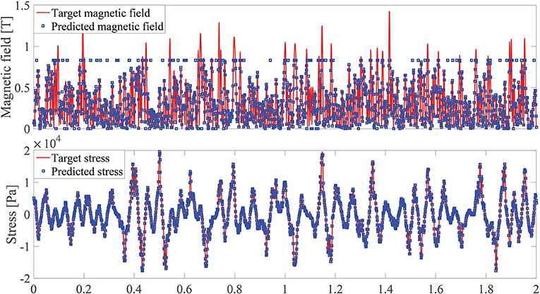
Figure 6. Magnetic field strength and stress vs. time. Line and square are the target and predicted values by the constitutive model and the inverse model, respectively.
3.2. Vehicle Suspension Model and Formulation of H-Infinity Controller
A quarter-car suspension model consists of a one-fourth car body, suspension components (spring plus MS rubber-based semi-active actuator), a wheel, and a tire are investigated in this study. For more details of the quarter-car suspension model, please see Figure 7. Symbols zs, zt, and zg represent the car body, wheel, and the ground displacement, respectively. The symbol u represents the control force that can be adjusted by the MS rubber suspension through changing the magnetic field. The model parameters for the quarter-car suspension model are ms = 504.5 kg, mt = 62 kg, , , and .
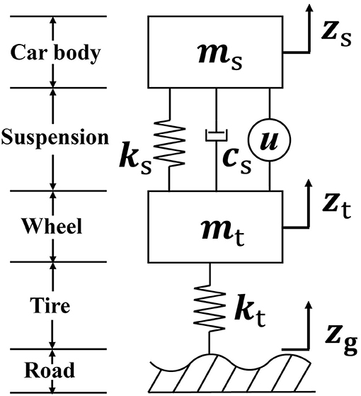
Figure 7. Schematic configuration of a quarter-car system with a MS rubber semi-active suspension.
In order to increase the driving performance, it is required that the transfer function from the road disturbance to the vertical acceleration of the car body (), the tire deflection (zt − zg), and the suspension deflection (zs − zt) should be small enough. Therefore, the controlled output is defined as . The measured output is defined as due to the fact that the suspension deflection (zt − zg) and the car-body velocity (żs) can be directly measured in practice. The dynamic equilibrium equation for the quarter-car system in state space form is
where
and
The parameters α and β in matrix E are weighting factors for the suspension and tire deflection, respectively. By tuning the weight factors, the trade-off among the car-body acceleration, suspension deflection, and the tire deflection can be controlled. The relation between the controlled force u and the measured output y is
where K = [ k1 k2 ] is the static output feedback control gain to be designed. To reduce the object transfer functions, robust control algorithms, such as LQR (Zhang et al., 2008; Zhang and Zhuan, 2020), H-2 (Li et al., 2003; Shukla et al., 2016), and H-infinity (Xie et al., 2004; Alma et al., 2011; Khot et al., 2017) controller, are often utilized. Compared with other controllers, the H-infinity norm measure the energy-to-energy gain between the external disturbance and the target outputs directly, which can be viewed as the worst-case gain in frequency domain. In this study, the H-infinity index is used for the controller design. According to Du et al. (2003), the system in Equation (19) is asymptotically stable with a disturbance attenuation γ > 0 if and only if there exist matrices G = GT > 0 and K such that
where sym(·) represents symmetric term, (*) denotes the symmetry matrix block, superscript T denotes matrix transpose, and I is the unit matrix. Normally, the bi-linear matrix inequality problem in Equation (29) cannot be solved directly. According to Ebihara et al. (2015), a coordinate-descent algorithm can be used to transfer the bi-linear matrix inequality problem in Equation (29) to several iterative linear matrix inequality problems, which can be solved in MATLAB LMI package directly. The dimensionless weighting factor α and β in Equation (24) are set to be 4 and 10, respectively. After applying the coordinate-descent algorithm-based iterative method, the H-infinity norm and the static output feedback control gain are obtained with γ = 8.441 and K = [ 8.9459 N m−1 2.9522 N s · m−1 ] × 103. The corresponding transfer functions from the road disturbance to the car acceleration (), suspension deflection (zs − zt), and the tire deflection (zt − zg) are in Figure 8. Compared with the open loop case, after applying H-infinity control algorithm, the peak gain for the car acceleration, suspension deflection, and the tire deflection are all reduced.
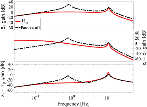
Figure 8. Transfer functions of the car acceleration (), suspension deflection (zs − zt), and tire deflection (zt − zg) where the gain magnitude is plotted in decibels with unit [dB].
4. Simulation Results
4.1. Design of MS Rubber Suspension and Numerical Implementation Method
The whole flowchart corresponding to the semi-active control of the MS rubber-based vehicle suspension system is given in Figure 9. After the external disturbance excitation is applied, the measured outputs y in Equation (19) is transmitted to the H-infinity controller as the input for the controller. Subsequently, a desired control force output is calculated by the H-infinity controller. However, the desired control force cannot be exerted directly. Therefore, the MS rubber inverse model in section 2.2 is utilized to determine the magnetic field corresponding to the desired control force. Finally, the actual force by the MS rubber suspension is applied to the quarter car system and new measured outputs are detected. In order to verify the vibration control performance of the MS rubber semi-active suspension, simulations under a bump and a random ground excitation are conducted. Before the simulation, the dimension of the MS rubber-based suspension is designed. To reduce the static deformation of the MS rubber suspension caused by the preloading of the car body mass, a linear spring with a stiffness of 2,100 N m−1 is installed in parallel with the MS rubber-based suspension. Sun et al. (2018) applied a multi-layer strategy for the MS rubber suspension in order to improve the deformation ability of the whole suspension, meanwhile ensuring the strain of each layer of MS rubber is small. Considering the simplest case, a multi-layer sandwich typed structure made of steel plate and MS rubber working in a shear mode are utilized. The total layer number of MS rubber is 10. For each layer MS rubber, the thickness is 0.04 m and the area is A = (0.10 m)2. Therefore, the approximate initial stiffness of the suspension by using the shear modulus of MS rubber at 5% strain amplitude under 1 Hz is
To illustrate the effectiveness of the control strategy, MS rubber suspension with the maximum stiffness (passive-on), MS rubber suspension with the minimum stiffness (passive-off), sky-hook on-off control strategy, and the active control strategy are simulated as well. The corresponding magnetic field control strategy for the sky-hook on-off control strategy is
In order to fully consider the magnetic field-, frequency-, and the strain amplitude-dependent dynamic behavior of MS rubber and obtain the structure response, the Newmark-beta method (Géradin and Rixen, 2014) based on implicit time integration is applied. The dynamic equilibrium equation of the whole system can be written as
where
and
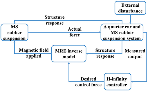
Figure 9. Close-loop flowchart of the whole quarter-car MS rubber suspension system.
First, an initial acceleration is obtained by the known response at the previous time step, qn−1,
where symbols with subscript n − 1 and n represent the response at the previous and the current time step, respectively. Subsequently, the predicted displacement q, velocity , and acceleration at the current time step are obtained by the average acceleration method
and
Following these, the residual force R is obtained
A threshold for the residual force κ = 1 × 10⁻³ N is set as the criteria for convergence. If R is larger than κ, a correction is applied by
and
where Δq = −R/S, with S as the Jacobian matrix for the system
After q is updated, the new residual force R is compared with the threshold κ. If the converge criteria is not satisfied, new rounds of iterations are applied until the convergence criteria is met. Finally, the structure response at the current time step can be obtained. Regarding ∂F/∂q, a finite difference numerical method can be applied to obtain its value (An et al., 2011).
4.2. Comparison on Bump Response
According to Sun et al. (2020), a road bump shock can be represented by
where H = 0.04 m, L = 5 m, and v = 25 m s−1 are the bump height, bump length, and the passing car velocity, respectively. After applying the numerical simulation analysis by the numerical methods in sections 2.2, 3.1, and 4.1, the comparison of the passive-on, passive-off, H-infinity semi-active, sky-hook on-off, and the active control strategies of the car-body acceleration, suspension deflection, and the tire deflection is given in Figure 10. Compared with passive-on and passive-off cases, a better vibration control effect can be achieved by the H-infinity semi-active, sky-hook on-off, and the active control strategies. The root mean square (RMS) values for the target responses (, zs − zt, and zt − zg) under different control strategies for the bump excitation are in Table 1. It can be found that the vibration control effect is the best for the active control case, followed by the H-infinity semi-active control and the sky-hook on-off control strategies. In Figure 11, the desired control force for the active control strategy and the actual applied force by the MS rubber semi-active suspension vs. suspension deflection are compared. The first and third quadrants in the figure correspond to the positive stiffness area, while the second and forth quadrants correspond to the negative stiffness area. Due to the positive shear modulus and the limited MR effect of MS rubber, the advantage of the active control strategy cannot be fully utilized by the MS rubber suspension. This conclusion can be verified by the partially overlapping between the desired control force-deflection curve and the actual applied force-deflection curve.
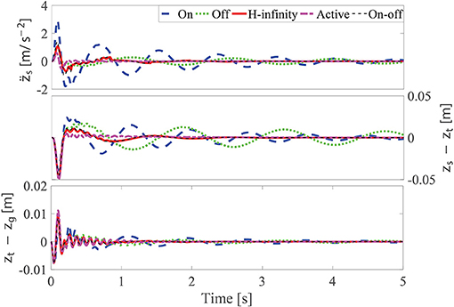
Figure 10. Comparison of the target responses at different control strategies under a bump excitation.
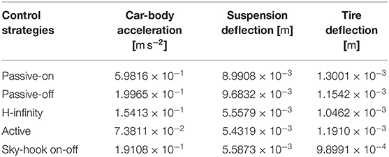
Table 1. RMS values of the target responses at different control strategies under a bump excitation.
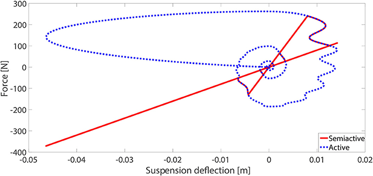
Figure 11. Comparison of the desired control force (red line) and the actual applied force (blue dotted line) vs. the MS rubber suspension deflection.
4.3. Comparison on a Random Response
After conducting the simulation under the bump response, a new round of simulation analysis under a random response is conducted. According to Sun et al. (2020), the road roughness can be treated as a random process with a given displacement power spectral density under frequency domain Gq(f) by
where Gq (n0) is the road roughness coefficient, and v is the car velocity. In the simulation, C road roughness is applied, where . The car velocity is set to be v = 60 km h−1. The corresponding road vibration signal generated by a fast Fourier transformation method (Beaulieu and Tan, 1997) with a sampling frequency of 1,000 Hz and a time length of 5 s is applied to the quarter car system. The comparison of the passive on, passive off, H-infinity semi-active, sky-hook on-off, and the active control strategies of the car-body acceleration, suspension deflection, and the tire deflection is given in Figure 12. The magnetic field vs. time under the H-infinity semi-active strategy and the sky-hook on-off control strategy is given in Figure 13. The result of the RMS values of the targeted responses are in Table 2. It can be found that compared with passive off and passive on cases, a better vibration reduction effect can be achieved by the H-infinity semi-active control strategy in controlling the car-body acceleration and the suspension deflection. Strangely, according to Table 2, the RMS value of the suspension and the tire deflection under the passive-on control strategy is the smallest. This can be attributed to the increase of the overall stiffness of the quarter-car system after implementing the maximum stiffness of the MS rubber suspension. Therefore, the deflection response under external excitation is smaller under the passive on case compared to other cases. However, the reduction of the car-body acceleration cannot be achieved directly by simply increasing the overall stiffness of the quarter-car system. This conclusion can be verified by the comparison of the car-body acceleration results under different control strategies where the acceleration under the passive on case is the largest. Furthermore, it can be found that there exists a flutter phenomena in the car body acceleration for the sky-hook on-off control strategy compared with the H-infinity control strategy. Due to the continuous adjusting of the magnetic field, the vibration control effect of the H-infinity semi-active control strategy is superior as compared to the sky-hook on-off control strategy.
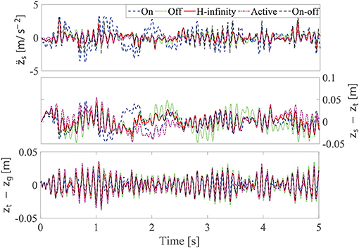
Figure 12. Comparison of the target responses at different control strategies under the random excitation.
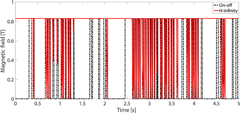
Figure 13. Comparison of the magnetic field under the sky-hook on-off control strategy and the H-infinity semi-active control strategy.
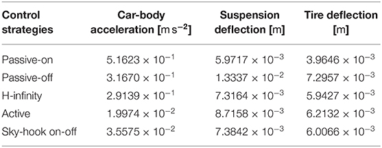
Table 2. RMS values of the target responses at different control strategies under a random excitation.
5. Conclusion
The fabrication, characterization, and the modeling of the mechanical performance of MS rubber along with the application of MS rubber in vehicle semi-active suspension are studied in this research. The matching between the simulated and measured shear modulus of MS rubber demonstrates that the applied constitutive model can depict the magnetic field-, frequency-, and strain amplitude-dependent shear modulus of MS rubber with accuracy. In order the desired control force can be implemented by the MS rubber semi-active device, an inverse model is developed to obtain the magnetic field corresponding to the desired control force. The matching between the target stress and the predicted stress generated by the calculated magnetic field through the inverse model indicates that the inverse model developed can track the desired control force with high accuracy. Furthermore, in order to explore the possible application of MS rubber in vehicle vibration control, a MS rubber semi-active suspension with the H-infinity control strategy applied to a quarter car model under a bump and a random ground excitation is studied. The results reveal that compared with the passive and the sky-hook on-off control cases, a better vibration reduction effect can be achieved by the MS rubber semi-active suspension with the H-infinity control strategy. However, in order to implement MS rubber in the vehicle vibration control area and achieve a good vibration reduction effect, issues such as further increase the MR effect of MS rubber, modeling the mechanical behavior of MS rubber with considering preload effect and the design optimization of the magnetic field generation circuit should be investigated. Besides, an increased vibration reduction effect is expected while adding an adjustable damping component to the current MS rubber-based suspension since the former adapts its damping while the latter adapts its stiffness. Furthermore, as the deflection of the suspension increases, the MR effect of MS rubber will weaken. Although the constitutive model can reflect the strain dependence of the MS rubber modulus, in practical applications, it is necessary to optimize the design of the MS rubber suspension to ensure that the MR effect of MS rubber can be utilized to the ultimate extent and achieve a good vibration control effect.
Data Availability Statement
The original contributions presented in the study are included in the article/supplementary material, further inquiries can be directed to the corresponding author/s.
Author Contributions
BW developed the theoretical formalism and performed the numerical simulations. TH helped to carry out the fabrication and characterization of MS rubber. XG and LK supervised the project and provided revisions to the scientific content of the manuscript. LS, JL, and ZX provided funding. All authors contributed to manuscript revision, read, and approved the submitted version.
Funding
Financial supports from the National Natural Science Foundation of China with Grant No. 11972343 and the National Key R&D Program of China with Grant No. 2018YFB1201703, the Anhui Key R&D program of China are gratefully acknowledged. The open access publication fee support by KTH Royal Institute of Technology is gratefully acknowledged.
Conflict of Interest
JL was employed by the company Anhui Weiwei Rubber Parts Group Co. Ltd.
The remaining authors declare that the research was conducted in the absence of any commercial or financial relationships that could be construed as a potential conflict of interest.
References
Alberdi-Muniain, A., Gil-Negrete, N., and Kari, L. (2012). Direct energy flow measurement in magneto-sensitive vibration isolator systems. J. Sound Vib. 331, 1994–2006. doi: 10.1016/j.jsv.2012.01.015
Alberdi-Muniain, A., Gil-Negrete, N., and Kari, L. (2013). Indirect energy flow measurement in magneto-sensitive vibration isolator systems. Appl. Acoust. 74, 575–584. doi: 10.1016/j.apacoust.2012.09.011
Alma, M., Martinez, J. J., Landau, I. D., and Buche, G. (2011). Design and tuning of reduced order h-infinity feedforward compensators for active vibration control. IEEE Trans. Control Syst. Technol. 20, 554–561. doi: 10.1109/TCST.2011.2119485
An, H., Wen, J., and Feng, T. (2011). On difference approximation of a matrix-vector product in the Jacobian-free Newton–Krylov method. J. Comput. Appl. Math. 236, 1399–1409. doi: 10.1016/j.cam.2011.09.003
Bastola, A., Ang, E., Paudel, M., and Li, L. (2019). Soft hybrid magnetorheological elastomer: gap bridging between MR fluid and MR elastomer. Colloids Surf. A Physicochem. Eng. Asp. 583:123975. doi: 10.1016/j.colsurfa.2019.123975
Beaulieu, N., and Tan, C. (1997). “An FFT method for generating bandlimited gaussian noise variates,” in GLOBECOM 97. IEEE Global Telecommunications Conference. Conference Record, Vol. 2 (IEEE), 684–688.
Berg, M. (1998). A non-linear rubber spring model for rail vehicle dynamics analysis. Veh. Syst. Dyn. 30, 197–212. doi: 10.1080/00423119808969447
Biglarbegian, M., Melek, W., and Golnaraghi, F. (2008). A novel neuro-fuzzy controller to enhance the performance of vehicle semi-active suspension systems. Veh. Syst. Dyn. 46, 691–711. doi: 10.1080/00423110701585420
Blom, P., and Kari, L. (2005). Amplitude and frequency dependence of magneto-sensitive rubber in a wide frequency range. Polym. Test. 24, 656–662. doi: 10.1016/j.polymertesting.2005.04.001
Blom, P., and Kari, L. (2011). A nonlinear constitutive audio frequency magneto-sensitive rubber model including amplitude, frequency and magnetic field dependence. J. Sound Vib. 330, 947–954. doi: 10.1016/j.jsv.2010.09.010
Blom, P., and Kari, L. (2012). The frequency, amplitude and magnetic field dependent torsional stiffness of a magneto-sensitive rubber bushing. Int. J. Mech. Sci. 60, 54–58. doi: 10.1016/j.ijmecsci.2012.04.006
Bustamante, R. (2010). Transversely isotropic nonlinear magneto-active elastomers. Acta Mech. 210, 183–214. doi: 10.1007/s00707-009-0193-0
Chen, L., Gong, X., Jiang, W., Yao, J., Deng, H., and Li, W. (2007a). Investigation on magnetorheological elastomers based on natural rubber. J. Mater. Sci. 42, 5483–5489. doi: 10.1007/s10853-006-0975-x
Chen, L., Gong, X., and Li, W. (2007b). Microstructures and viscoelastic properties of anisotropic magnetorheological elastomers. Smart Mater. Struct. 16:2645. doi: 10.1088/0964-1726/16/6/069
Chen, L., and Jerrams, S. (2011). A rheological model of the dynamic behavior of magnetorheological elastomers. J. Appl. Phys. 110:013513. doi: 10.1063/1.3603052
Choi, S., Lee, S., and Park, Y. (2001). A hysteresis model for the field-dependent damping force of a magnetorheological damper. J. Sound Vib. 245, 375–383. doi: 10.1006/jsvi.2000.3539
Danas, K., Kankanala, S., and Triantafyllidis, N. (2012). Experiments and modeling of iron-particle-filled magnetorheological elastomers. J. Mech. Phys. Solids 60, 120–138. doi: 10.1016/j.jmps.2011.09.006
Davis, L. (1999). Model of magnetorheological elastomers. J. Appl. Phys. 85, 3348–3351. doi: 10.1063/1.369682
Dorfmann, A., and Ogden, R. (2003). Magnetoelastic modelling of elastomers. Eur. J. Mech. A Solids 22, 497–507. doi: 10.1016/S0997-7538(03)00067-6
Du, H., Lam, J., and Sze, K. Y. (2003). Non-fragile output feedback h-infinity vehicle suspension control using genetic algorithm. Eng. Appl. Artif. Intell. 16, 667–680. doi: 10.1016/j.engappai.2003.09.008
Du, H., Li, W., and Zhang, N. (2011). Semi-active variable stiffness vibration control of vehicle seat suspension using an MR elastomer isolator. Smart Mater. Struct. 20:105003. doi: 10.1088/0964-1726/20/10/105003
Du, X., Yu, M., Fu, J., and Huang, C. (2020). Experimental study on shock control of a vehicle semi-active suspension with magneto-rheological damper. Smart Mater. Struct. 29:074002. doi: 10.1088/1361-665X/ab859e
Ebihara, Y., Peaucelle, D., and Arzelier, D. (2015). S-Variable Approach to LMI-Based Robust Control. New York, NY: Springer.
Fu, J., Bai, J., Lai, J., Li, P., Yu, M., and Lam, H.-K. (2019). Adaptive fuzzy control of a magnetorheological elastomer vibration isolation system with time-varying sinusoidal excitations. J. Vib. Control 456, 386–406. doi: 10.1016/j.jsv.2019.05.046
Géradin, M., and Rixen, D. J. (2014). Mechanical Vibrations: Theory and Application to Structural Dynamics. Chichester: John Wiley & Sons.
Haupt, P., and Lion, A. (2002). On finite linear viscoelasticity of incompressible isotropic materials. Acta Mech. 159, 87–124. doi: 10.1007/BF01171450
Heißing, B., and Ersoy, M. (2011). “Ride comfort and NVH,” in Chassis Handbook, eds, B. Heißing and M. Ersoy. (Wiesbaden: Springer), 421–448.
Hu, Z., Yan, H., Qiu, H., Zhang, P., and Liu, Q. (2012). Friction and wear of magnetorheological fluid under magnetic field. Wear 278, 48–52. doi: 10.1016/j.wear.2012.01.006
Jiang, W., Yao, J., Gong, X., and Chen, L. (2008). Enhancement in magnetorheological effect of magnetorheological elastomers by surface modification of iron particles. Chin. J. Chem. Phys. 21:87. doi: 10.1088/1674-0068/21/01/87-92
Jin, T., Liu, Z., Sun, S., Ren, Z., Deng, L., Yang, B., et al. (2020). Development and evaluation of a versatile semi-active suspension system for high-speed railway vehicles. Mech. Syst. Signal Process. 135:106338. doi: 10.1016/j.ymssp.2019.106338
Jolly, M. R., Carlson, J. D., and Munoz, B. C. (1996). A model of the behaviour of magnetorheological materials. Smart Mater. Struct. 5:607. doi: 10.1088/0964-1726/5/5/009
Jung, H.-J., Eem, S.-H., Jang, D.-D., and Koo, J.-H. (2011). Seismic performance analysis of a smart base-isolation system considering dynamics of MR elastomers. J. Intell. Mater. Syst. Struct. 22, 1439–1450. doi: 10.1177/1045389X11414224
Kankanala, S., and Triantafyllidis, N. (2004). On finitely strained magnetorheological elastomers. J. Mech. Phys. Solids 52, 2869–2908. doi: 10.1016/j.jmps.2004.04.007
Kari, L. (2017). Dynamic stiffness of chemically and physically ageing rubber vibration isolators in the audible frequency range. Contin. Mech. Thermodyn. 29, 1027–1046. doi: 10.1007/s00161-017-0569-7
Kari, L. (2020). Are single polymer network hydrogels with chemical and physical cross-links a promising dynamic vibration absorber material? A simulation model inquiry. Materials 13:5127. doi: 10.3390/ma13225127
Khot, S., Yelve, N. P., Kumar, P., Purohit, G. A., and Singh, D. (2017). “Implementation of H-infinity controller in experimental active vibration control of a cantilever beam,” in 2017 International Conference on Nascent Technologies in Engineering (ICNTE) (Mumbai: IEEE), 1–5.
Li, H. J., James Hu, S.-L., and Jakubiak, C. (2003). H2 active vibration control for offshore platform subjected to wave loading. J. Sound Vib. 263, 709–724. doi: 10.1016/S0022-460X(02)01095-7
Li, J., Gong, X., Xu, Z., and Jiang, W. (2008). The effect of pre-structure process on magnetorheological elastomer performance. Int. J. Mater. Res. 99, 1358–1364. doi: 10.3139/146.101775
Li, W., Zhou, Y., and Tian, T. (2010). Viscoelastic properties of MR elastomers under harmonic loading. Rheol. Acta 49, 733–740. doi: 10.1007/s00397-010-0446-9
Liao, G., Gong, X., and Xuan, S. (2013). Phase based stiffness tuning algorithm for a magnetorheological elastomer dynamic vibration absorber. Smart Mater. Struct. 23:015016. doi: 10.1088/0964-1726/23/1/015016
Lion, A., and Kardelky, C. (2004). The Payne effect in finite viscoelasticity: constitutive modelling based on fractional derivatives and intrinsic time scales. Int. J. Plast. 20, 1313–1345. doi: 10.1016/j.ijplas.2003.07.001
Liu, C., Hemmatian, M., Sedaghati, R., and Wen, G. (2020). Development and control of magnetorheological elastomer-based semi-active seat suspension isolator using adaptive neural network. Front. Mater. 7:171. doi: 10.3389/fmats.2020.00171
Lokander, M., and Stenberg, B. (2003). Performance of isotropic magnetorheological rubber materials. Polym. Test. 22, 245–251. doi: 10.1016/S0142-9418(02)00043-0
Martins, I., Esteves, M., Da Silva, F. P., and Verdelho, P. (1999). “Electromagnetic hybrid active-passive vehicle suspension system,” in 1999 IEEE 49th Vehicular Technology Conference (Cat. No. 99CH36363), Vol. 3 (Houston, TX: IEEE), 2273–2277.
Meng, X., Wang, Z., Liu, B., and Wang, S. (2018). Third-order polynomial model for analyzing stickup state laminated structure in flexible electronics. Acta Mech. Sin. 34, 48–61. doi: 10.1007/s10409-017-0670-y
Phu, D. X., and Choi, S.-B. (2019). Magnetorheological fluid based devices reported in 2013–2018: mini-review and comment on structural configurations. Front. Mater. 6:19. doi: 10.3389/fmats.2019.00019
Saxena, P., Hossain, M., and Steinmann, P. (2014). Nonlinear magneto-viscoelasticity of transversally isotropic magneto-active polymers. Proc. Math. Phys. Eng. Sci. 470:20140082. doi: 10.1098/rspa.2014.0082
Serra-Aguila, A., Puigoriol-Forcada, J., Reyes, G., and Menacho, J. (2019). Viscoelastic models revisited: characteristics and interconversion formulas for generalized Kelvin–Voigt and Maxwell models. Acta Mech. Sin. 35, 1191–1209. doi: 10.1007/s10409-019-00895-6
Shen, Y., Golnaraghi, M. F., and Heppler, G. R. (2004). Experimental research and modeling of magnetorheological elastomers. J. Intell. Mater. Syst. Struct. 15, 27–35. doi: 10.1177/1045389X04039264
Shukla, P., Ghodki, D., Manjarekar, N. S., and Singru, P. M. (2016). A study of H infinity and H2 synthesis for active vibration control. IFAC PapersOnLine 49, 623–628. doi: 10.1016/j.ifacol.2016.03.125
Simo, J. C., and Hughes, T. J. (2006). Computational Inelasticity, Vol. 7. New York, NY: Springer Science & Business Media.
Sun, S., Yang, J., Du, H., Zhang, S., Yan, T., Nakano, M., et al. (2018). Development of magnetorheological elastomers-based tuned mass damper for building protection from seismic events. J. Intell. Mater. Syst. Struct. 29, 1777–1789. doi: 10.1177/1045389X17754265
Sun, W., Gao, H., and Shi, P. (2020). Advanced Control for Vehicle Active Suspension Systems. Cham: Springer.
Tong, Y., Dong, X., and Qi, M. (2018). Improved tunable range of the field-induced storage modulus by using flower-like particles as the active phase of magnetorheological elastomers. Soft Matter 14, 3504–3509. doi: 10.1039/C8SM00359A
Wang, B., and Kari, L. (2019). Modeling and vibration control of a smart vibration isolation system based on magneto-sensitive rubber. Smart Mater. Struct. 28:065026. doi: 10.1088/1361-665X/ab1ab4
Wang, B., and Kari, L. (2020). A visco-elastic-plastic constitutive model of isotropic magneto-sensitive rubber with amplitude, frequency and magnetic dependency. Int. J. Plast. 132:102756. doi: 10.1016/j.ijplas.2020.102756
Wang, J., Li, S., Cui, J., and Man, L. (2011). “Parameter inversion of constitutive model of soil using neural networks,” in Advances in Computer Science, Intelligent System and Environment (Berlin: Springer), 417–420.
Wang, Q., Dong, X., Li, L., and Ou, J. (2017). Study on an improved variable stiffness tuned mass damper based on conical magnetorheological elastomer isolators. Smart Mater. Struct. 26:105028. doi: 10.1088/1361-665X/aa81e8
Wang, Q., Dong, X., Li, L., and Ou, J. (2018). Mechanical modeling for magnetorheological elastomer isolators based on constitutive equations and electromagnetic analysis. Smart Mater. Struct. 27:065017. doi: 10.1088/1361-665X/aabdb5
Wilson, C. M. D., and Abdullah, M. M. (2010). Structural vibration reduction using self-tuning fuzzy control of magnetorheological dampers. Bull. Earthq. Eng. 8, 1037–1054. doi: 10.1007/s10518-010-9177-7
Xie, S. L., Zhang, X. N., Zhang, J. H., and Yu, L. (2004). H(infinity) robust vibration control of a thin plate covered with a controllable constrained damping layer. J. Vib. Control 10, 115–133. doi: 10.1177/1077546304032994
Yang, J., Sun, S., Tian, T., Li, W., Du, H., Alici, G., et al. (2016). Development of a novel multi-layer MRE isolator for suppression of building vibrations under seismic events. Mech. Syst. Signal Process. 70, 811–820. doi: 10.1016/j.ymssp.2015.08.022
Yang, Z., Fu, J., Bai, J., Liao, G., and Yu, M. (2019). “An inverse model of magnetorheological elastomer isolator with neural network,” in 2019 Chinese Control And Decision Conference (CCDC) (Nanchang: IEEE), 1664–1667.
Zhang, J., He, L., Wang, E., and Gao, R. (2008). “A LQR controller design for active vibration control of flexible structures,” in 2008 IEEE Pacific-Asia Workshop on Computational Intelligence and Industrial Application, Vol. 1 (Washington, DC: IEEE), 127–132.
Zhang, L., and Zhuan, X. (2020). Vibration control method of an electromagnetic isolation system based on LQR and coevolutionary NGA. Shock Vib. 2020:6384160. doi: 10.1155/2020/6384160
Zhang, W., Gong, X., and Chen, L. (2010). A Gaussian distribution model of anisotropic magnetorheological elastomers. J. Magn. Magn. Mater. 322, 3797–3801. doi: 10.1016/j.jmmm.2010.08.004
Zhang, X., Gong, X., Zhang, P., and Wang, Q. (2004). Study on the mechanism of the squeeze-strengthen effect in magnetorheological fluids. J. Appl. Phys. 96, 2359–2364. doi: 10.1063/1.1773379
Zhao, R., Kim, Y., Chester, S. A., Sharma, P., and Zhao, X. (2019). Mechanics of hard-magnetic soft materials. J. Mech. Phys. Solids 124, 244–263. doi: 10.1016/j.jmps.2018.10.008
Zhou, G. (2003). Shear properties of a magnetorheological elastomer. Smart Mater. Struct. 12:139. doi: 10.1088/0964-1726/12/1/316
Zhu, Y., Gong, X., Dang, H., Zhang, X., and Zhang, P. (2006). Numerical analysis on magnetic-induced shear modulus of magnetorheological elastomers based on multi-chain model. Chin. J. Chem. Phys. 19, 126–130. doi: 10.1360/cjcp2006.19(2).126.5
Keywords: magneto-sensitive rubber, vehicle vibration control, constitutive model, magnetic-dependent dynamic modulus, frequency-dependent dynamic modulus, strain amplitude-dependent dynamic modulus, MS rubber semi-active suspension
Citation: Wang B, Hu T, Shen L, Li J, Xu Z, Kari L and Gong X (2021) Magneto-Sensitive Rubber in a Vehicle Application Context – Exploring the Potential. Front. Mater. 8:659780. doi: 10.3389/fmats.2021.659780
Received: 28 January 2021; Accepted: 20 April 2021;
Published: 04 June 2021.
Edited by:
Jinglei Yang, Hong Kong University of Science and Technology, Hong KongReviewed by:
Yancheng Li, University of Technology Sydney, AustraliaXingzhe Wang, Lanzhou University, China
Tongqing Lu, Xi'an Jiaotong University, China
Xianzhou Zhang, Independent Researcher, Tomago, NSW, Australia
Copyright © 2021 Wang, Hu, Shen, Li, Xu, Kari and Gong. This is an open-access article distributed under the terms of the Creative Commons Attribution License (CC BY). The use, distribution or reproduction in other forums is permitted, provided the original author(s) and the copyright owner(s) are credited and that the original publication in this journal is cited, in accordance with accepted academic practice. No use, distribution or reproduction is permitted which does not comply with these terms.
*Correspondence: Leif Kari, bGVpZmthcmlAa3RoLnNl; Xinglong Gong, Z29uZ3hsQHVzdGMuZWR1LmNu