 Honghui Zhang
 Zhiyuan Zou1
- 1College of Opto-Electronic Engineering, Chongqing University, Chongqing, China
- 2The Key Laboratory for Opto-Electronic Technology and System, Ministry of Education, Chongqing University, Chongqing, China
- 3Chongqing Tiema Industries Group Company Limited, Chongqing, China
In light of the insurmountable sedimentation of magnetorheological (MR) fluid, it is of great significance to ensure the performability of an MR damper by introducing a sensing method for MR fluid settling, and a key indicator to identify the health status of the MR damper is critical. However, the settling monitoring system for MR fluid can nowadays only function in a laboratory with transparent and non-magnetic tubes, which is not qualified for the in-situ sensing in a steel-made cylinder. Under the analysis of an open plate capacitor (OPC) configuration, the relationship between the concentration of magnetorheological fluid and the capacitance is investigated by simulation and experiments, and based on OPC, an in-situ sensing method for the settlement monitoring of magnetorheological fluid is designed. Long-time settling monitoring is carried out with home-made MR fluids, and the test results show that the sensing method can effectively reflect the status of settled MR fluids, and has the potential to be utilized in the identification of MR fluid compression points, which provides the strategic signal for the probable active or operational re-dispersing of MR fluid.
Introduction
Magnetorheological (MR) fluid was first described in 1948 by J. Rabinow, 1 year after Winslow's patent for electrorheological (ER) fluid, but MR fluid prevails with its much higher mechanical performance in relatively low voltages. MR fluid is a suspension of magnetically soft and micron-sized particles in a carrier liquid, typically carbonyl iron (CI) particles and silicon oil, and the rheological properties can be controlled by an applied magnetic field (Rankin et al., 1999). When free of the magnetic field, the particles are dispersed uniformly in the carrier liquid by strong surfactants and the MR fluid generally performs like a quasi-Newtonian fluid (Chen et al., 2015; Aruna et al., 2019).
Under a magnetic field, the particles are aggregated to form chain-like clusters which can undertake strong shear deformation like a Bingham fluid, and the more intense magnetic flux, the higher yield stress exhibited. The phase transition between Newtonian and Bingham behavior is rapid, reversible, and insensitive to temperature over broad temperature ranges, and thus MR fluid can provide simple, quiet, and rapid-response interfaces between electronic controls and mechanical systems, and has been applied to various types of devices such as dampers, clutches, brakes, valves, etc.
Regardless of the ever-developing additives and surfactants, MR fluid tends to be settled because of the density mismatch between the dispersed phase and carrier fluid, which causes the MR damper to stick or degrade, i.e., the performability of the MR damper cannot be ensured if it is standing still for a long time such as the one adopted in earthquake mitigation. The contemporary MR damper, shown in Figure 1, mainly works via the principle of flow mode and shear mode with a single tube structure, the accumulator accommodates the volume change, which occurs due to the piston rod getting in and out of the cylinder, which is always located at the bottom end of the cylinder, and a floating piston serves as an isolator between the chambers. According to the flow analysis, the particles aggregated onto the upper end of the piston can be regarded as the recoverable sediment zone when formed after long-time standing of the MR damper, and re-dispersed by penetrating flow induced by the piston reciprocation. But the MR fluid only acts as a scouring flow for the unrecoverable sediment zone over the floating piston because the MR fluid flow stops there, and the MR damper degrades because the particles cannot be brought into the main stream of the MR fluid, which inevitably lowers the actual concentration of MR fluid. Consequently, a system should be established to characterize the health of the MR damper, determining the aggregation state of the MR fluid in the unrecoverable sediment zone is a potential way.
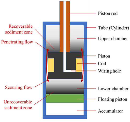
Figure 1. Flow analysis of the MR fluid in a typical MR damper.
The most commonly used method for MR fluid sedimentation monitoring is visual observation, Gorodkin et al. (2000), Chen and Chen (2003), and Ngatu and Wereley (2007) tracked the mudline in MR fluid settling using a fixed inductor. Xie et al. (2015) investigated the sedimentation comparison between silicone oil and HVLP-based MR fluid, and the sedimentation characterization based on a vertical axis inductance monitoring system (VAIMS) was carried out (Choi et al., 2016) by vertically translating an inductor sensor along the MR fluid column which is enclosed in a transparent tube, and recording the inductance value in a specified time interval until the MR fluid settled to a stable condition in the column. Wen et al. (2019) optimized the VAIMS with a LARS sensor to better locate MR fluid layering while it settled. Cheng et al. (2016) established a complicated system to monitor MR fluid settling via the thermal conductivity change with the concentration, in which the thermal conductivity was monitored at a fixed location but the system was severely dependent on the thermal environment.
Most of the monitoring methods proposed for MR fluid sedimentation were carried out in the laboratory, and the MR fluid was enclosed by a non-magnetic tube, which is favorable for MR fluid preparation and optimization, but it is futile when we hope to investigate the MR fluid which services an actual device such as a damper or clutch. Vezys et al. (2018) developed a method for sedimentation sensing in a MR brake via resistivity measuring, in which the MR fluid sedimentation is characterized with the magnetic field strength and the time of standing still, but failed to correlate the resistivity with the concentration of MR fluid. Gillet et al. (2020) proposed a novel method to track the degradation of an MR clutch by correlating the clearness percentage of MR fluid with the established durability metric of “life dissipated energy” (LDE), where the clearness of MR fluid is sensed by an optical red green blue sensor.
It is obvious that the sedimentation monitoring of MR fluid is of great significance for ongoing applications, but it is difficult to relate the real concentration of the MR fluid with device performance such as dampers, brakes, and clutches, because of the opaqueness and immeasurable inductance in a real steel-made cylinder. Numerical simulations should play an important role for the promotion of effective sedimentation monitoring. There are other factors inducing the degradation of MR devices, but MR fluid sedimentation constructs the greatest challenge for the performability of an MR damper, so an in-situ capacitance sensing method is proposed in this paper to better illustrate the MR fluid concentration in the settling process via simulation and experiments.
Theoretical Bases
As we know, a parallel plates capacitor is comprised of two face-to-face placed plates and the facing area of the plates is proportional to the capacitance. But when used as a sensing element, the gap distance or the dielectric coefficient of the medium between the plates often interact with the sensed quantities to regulate the capacitance. The dielectric coefficient of the MR fluid will be regulated with the concentration change in the sedimentation of the MR fluid, but the particles will be prevented from getting into the capacitor gap because of the obstruction of plates or the small distance between the plates, no matter if the parallel capacitor is placed horizontally or obliquely as shown in Figure 2. An open plate capacitor (OPC), with a bottom-placed horizontal plate and a pillar plate in the center, is proposed in this paper to designate the settling of MR fluid, in which the settled particles will be gathered onto the horizontal plate and effectively change the concentration of the MR fluid enclosed.
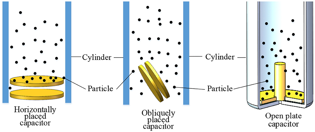
Figure 2. Capacitor configuration for settlement sensing of MR fluid.
As show in Figure 3a, the sensing element is in-situ because the capacitor is bottom-placed in the steel-made cylinder, and the operation of the MR damper is not affected while the settling monitoring of the MR fluid is continuously operating. A wiring hole is in the center of the pillar plate and an isolating gap is between the two insulated plates to avoid circuit shorting. The horizontal plate is 41 mm in diameter, a little smaller than the steel cylinder which is 42 mm in diameter, and the pillar plate is 8 mm in diameter and of 15 mm in height. To explore the relationship between the concentration of the MR fluid and the capacitance of the open plate capacitor, a COMSOL finite element model is established and shown in Figure 3b. In the simulation, a two-dimensional axial symmetric model is employed for the open plate capacitor because of the physical essentials. The boundary conditions are listed as following: the pillar plate is set to be a potential terminal with a 1 V surface voltage, and the horizontal plate is set to be a grounding terminal.
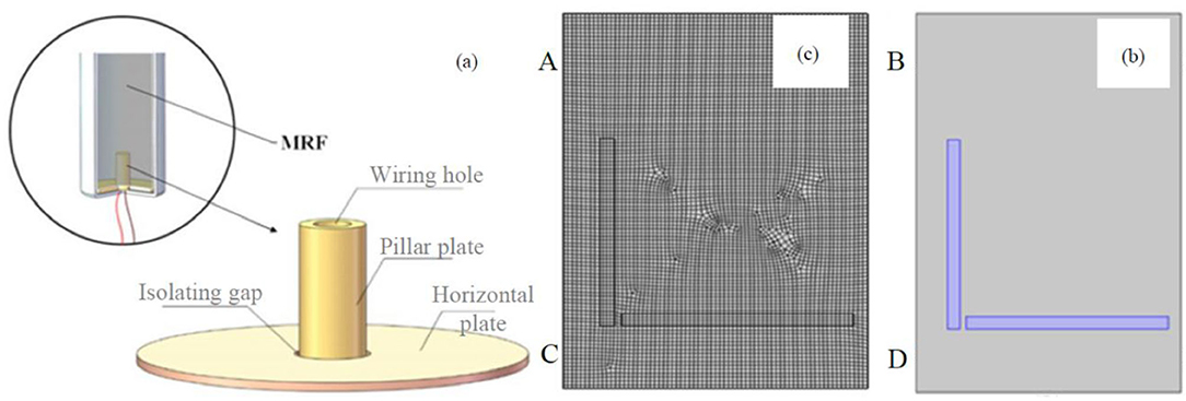
Figure 3. The electromagnetic model of an open plate capacitor; (a) sensor configuration; (b) electromagnetic model; (c) mesh grid of the finite element model.
In Figure 3c, the open plate capacitor is assumed to be placed in a uniformly distributed MR fluid, and the physical boundaries of AB, BD, and CD are set to be zero electric charge, and AC is the symmetrical axis. The dielectric coefficient of plates is set to be a two-phase augmented composite relative to the MR fluid, and the equivalent relative dielectric coefficient ε satisfies the following Maxwell–Garnett model (Garnett, 1904):
Where φ is the fraction of carbonyl iron (CI) particles of MR fluid in weight, and εp is the relative dielectric coefficient of the CI particles and is set to 60. εm is the relative dielectric coefficient of the solute and is set to 2, and ρp, ρl are the densities of the dispersed particle and dispersing medium, 7,900 and 1,000 kg/m3, respectively, in this simulation. The discretized finite element model is substituted into the ES solution of COMSOL software and the results are shown in Figure 4.
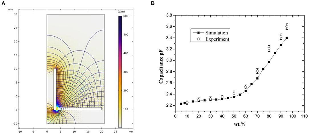
Figure 4. The electromagnetic simulation of the open plate capacitor; (A) electric field distribution at 20wt.%; (B) the results between the capacitance and the MR fluid concentration.
From Figure 4A, the electric field in the MR fluid is mainly concentrated at the adjacent zone of the pillar and horizontal plates when the open plate capacitor is applied with 1 V in the pillar plate, and the nearer to the pillar plate, the stronger the electric field. The maximum is 1,217 V/m, the equipotential surface is distributed bowl-like between the two plates. From Figure 4B, with the heightening of the MR fluid concentration, the capacitance of the open plate capacitor is increased from 2.23 to 2.71 pF, following an accelerating trend with the MR fluid concentration. Additionally, the results show that there is a deterministic relationship between the MR fluid concentration and the capacitance, and this makes it possible to measure the settled MR fluid concentration by sensing the capacitance output of the open plate capacitor. With LCR equipment in precision of 0.01 pF, the simulated results are also experimentally validated in Figure 4B using the home-made MR fluid with simply mixed CI particles in silicone oil with specific concentrations (the details are in section Experiment). The simulation coincides well with the experiment, but the simulation is a little smaller in value because of the error from the Maxwell–Garnett model in high particle concentration. And the result shows that the capacitance-based sensing method will be more sensitive in high MR fluid concentrations, and once the particles settle to a relatively high concentration, the sensing will be more accurate.
Experiment
MR Fluid Preparation
To speed up the experiment, the home-made MR fluid is prepared to accelerate particle settling, the CI particles with d50 = 5 μm and the silicone oil with a viscosity of 100 cps are used. The metering in the MR fluid preparation is relatively easy because the concentration is determined by weight ratio. The weight ratio of CI particles and silicone oil is 4:1 when taking an 80% MR fluid concentration as an example, ~200 ml of silicone oil is weighed by a balance in 0.1 g precision and poured into a transparent beaker and the CI particles (four times the weight of the oil) are mixed into the silicone oil, and then the blend is adequately stirred and mixed by a muddler before measurement, the uniformity of the MR fluid is determined by visual information and manual interaction. The range of MR fluid concentration in weight ratio can be effectively broadened to nearly 100%, and in this paper, MR fluid samples of 10–90% with a 10% interval, and an additional 95% concentration in weight ratio are prepared to validate the simulation results, but only MR fluids, initially in relatively low concentrations of 20, 30, and 40%, are used to track particle settling for exploring the settling process from low to high concentrations. The prepared MR samples are designated as the weight ratio with a prefix of MRF, such as MRF20, MRF30, and MRF40.
Test Setup
The test setup is shown in Figure 5A and the steel cylinder is held on a stand with the open plate capacitor placed at the bottom, LCR equipment is used to measure the capacitance, and a laptop is included. The steel cylinder is 120 mm in height and the upper end is not covered to allow us to pour and remove the MR fluid. The leading wire is fed through the wiring hole of the pillar plate and the end cover of the cylinder, and then the wiring hole is sealed with epoxy resin. VICTOR brand LCR equipment is used and in a precision of 0.01 pF, the frequency of the capacitance reading is set to 100 kHz.
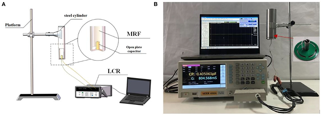
Figure 5. The test setup for MR fluid settlement monitoring and capacitance calibration. (A) Scheme diagram. (B) Experiment setup.
The Calibration Test
All seven prepared samples are adopted to calibrate the simulation result of the relationship between the MR fluid concentration and the capacitance of the open plate capacitor. Pouring 100 ml of the prepared sample into the cylinder from the upper opening of the cylinder and ensuring the pillar plate is totally immersed in the MR fluid, the capacitance outputs are recorded simultaneously for samples in each concentration, respectively, and the output values are averaged by five-time measurements for each sample. The cylinder functions as an electromagnetic shield and the wall is connected to the grounding terminal of the LCR equipment to avoid electromagnet interference. Because of the long process of MR fluid sedimentation monitoring, the test setup is put into a thermostatic chamber and kept at 20°C.
Sedimentation Monitoring
Based on the in-situ monitoring test setup, sedimentation monitoring of MR fluids is carried out with different concentrations, only MRF20, MRF30, and MRF40 are used in the monitoring to speed up the process and the capacitance can be observed from an initial low concentration to the settled high concentration, and all the testing MR fluids used are 100 ml in volume. Because the mudline formation is not easily observed in the steel-made cylinder, the corresponding testing sample of MR fluids are also put in transparent tubes with the same volume as a contrast, the emergence and following descent of the mudline are recorded with a time interval of 10 min until they remain unchanged. The capacitance acquisition is started when the testing MR fluids are poured into the steel-made cylinders and the transparent tubes simultaneously, and the acquired capacitance is transferred into the concentration of the MR fluid according to the calibration test shown in Figure 5B.
Results and Discussion
The results of settlement monitoring are shown in Figure 6. As shown in Figure 6A, the mudline height descends and the MRF20 concentration increases at the bottom of the cylinder with increasing time because of the sedimentation. The mudline descends from initially 180 mm to 121 mm and the concentration rises from 20.0 to 64.5 wt.%, respectively, after 100 min of settling. The mudline heights are 55 and 23 mm, respectively, at the second and the third hundredth minute, and eventually end at 8 mm, but the concentrations are 90.1 and 95.1 wt.% in the same time scale, and then finally approach 100%. As a contrast (as shown in Figures 6B,C), at the time scale of the 1st, 2nd, and 3rd hundredth minute, the mudline heights and concentrations for MRF30 are 144 mm, 64.5 wt.%, 109 mm, 80.6 wt.%, and 70 mm, 86.9 wt.%, and the counterparts for MRF40 are 162 mm, 44.5 wt.%, 137 mm, 51.5 wt.%, and 110 mm, 59.7 wt.%.
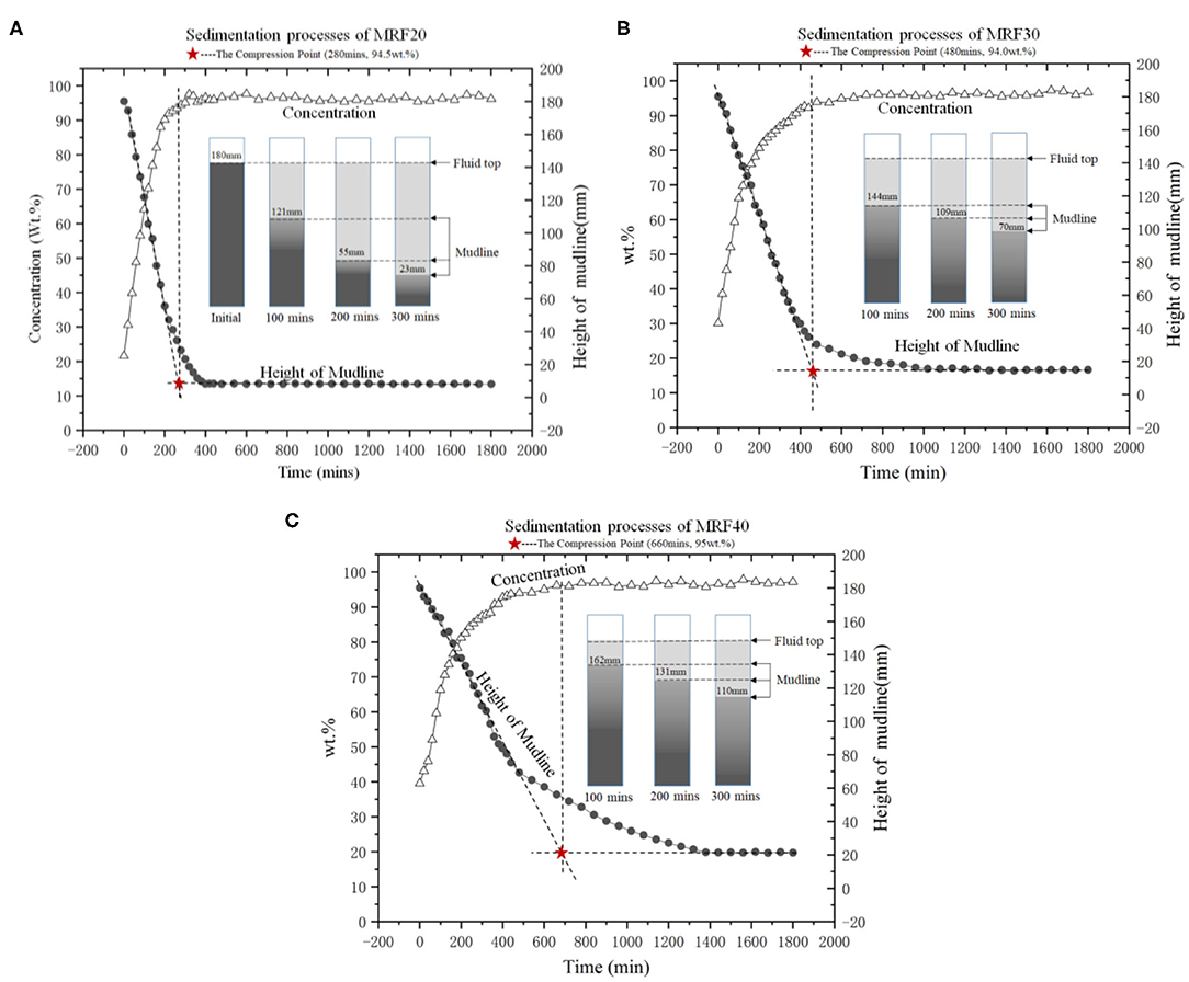
Figure 6. Sedimentation processes of MRF: (A) MRF20; (B) MRF30; (C) MRF40.
For each observation, the descent of the mudline height gets slower with the increment of the measured concentration, this can be seen when the concentration of the MR fluid is low, the distance between particles is enough to prevent the interaction between particles, and the Stokes law is satisfied correspondingly. However, when the concentration of MR fluid gets higher, the distance between particles reduces and even results in contact between them, the conflict and squeeze between particles will delay the settling of the particles.
Besides, the comparison between the settlement of different MR fluid samples shows that the higher the initial concentration of the MR fluid, the slower the sedimentation will be. The time lengths needed for the fully settled status of MRF20, MRF30, and MRF40 are about 400, 950, and 1,400 min, respectively. Additionally, initial sedimentation presents a relatively steady settling rate with a constant slope, and the lower the concentration of MR fluid, the bigger the slope. According to Kynch's theory of sedimentation (Kynch, 1952), the process can be divided into a constant settling region, transition region, and consolidation region, and there is a compression point in the transition region, which can be determined theoretically by the tangent method. For the settling curve of MRF20, MRF30, and MRF40, the compression points are determined as in Figure 6, and the corresponding time scales are about 280, 480, and 660 min, respectively.
In addition, as a critical sedimentation point identifies the point at which the pulp-supernatant interface goes from zone settling into compression, the compression point will be the starting point of the sediment consolidation, and can be seen as a key indicator of the health status of the MR damper. It is obvious that the time of compression points appearance diverges with the concentration of MR fluid, however, the relatively constant concentration of MR fluid is measured at the cylinder bottom and it is about 94.5% in weight ratio. Accordingly, a re-dispersing mechanism should be introduced to actively or operationally disperse the settled MR fluid to avoid the failure of the device, in-situ capacitance sensing will play an important role as the triggering signal to start the re-dispersing mechanism. For commercial MR fluid, the appearance of the compression point can be expected much later, but the measured capacitance of the open plate capacitor, thus the concentration of MR fluid, will be expected.
Conclusion
For the settling characteristics of MR fluid in a steel-made cylinder of a real MR damper, an open plate capacitor configuration based on in-situ sensing is proposed in this paper and LCR equipment is used as the acquisition of the capacitance, which is regulated by the settled MR fluid. The relationship between the capacitance value and the concentration of MR fluid in weight ratio is calibrated by simulation and experiments, and long-time settlement monitoring is carried out to pursue an effective indicator to reflect the status of settled MR fluid and act as a representation of the performability of a promising MR damper. The following conclusions can be drawn in the sedimentation of MR fluid:
The capacitance of open plate capacitor is positively correlated with the concentration of MR fluid, the higher the concentration, the higher the capacitance and the faster the increment of the capacitance. However, the higher the concentration of MR fluid, the slower the settling will be.
In the experiments, although the occurrence of Kynch's theory-based compression point diverges temporally, the corresponding concentration almost stays constant at about 94.5 wt.%, and the characterization of the open plate capacitor is qualified to be the triggering signal to start an active or operational re-dispersing mechanism for an MR damper, which confronts a risk of failure under MR fluid sedimentation.
Data Availability Statement
The raw data supporting the conclusions of this article will be made available by the authors, without undue reservation.
Author Contributions
HZ is the corresponding author for this submission, and he started and supervised the entire research. ZZ finished all the experiments for this paper. NA and NX jointly completed the simulation job, and finally, XY contributed on the test-up and the experimental schemes. All authors are contributing on the manuscript and the research.
Funding
This research is supported by the Natural Science Foundation of China (No. 62073050).
Conflict of Interest
XY was employed by the Chongqing Tiema Industries Group Company Limited.
The remaining authors declare that the research was conducted in the absence of any commercial or financial relationships that could be construed as a potential conflict of interest.
References
Aruna, M. N., Rahman, M. R., Joladarashi, S., and Kumar, H. (2019). Influence of additives on the synthesis of carbonyl iron suspension on rheological and sedimentation properties of magnetorheological (MR) fluids. Mater. Res. Express 6, 086105. doi: 10.1088/2053-1591/ab1e03
Chen, F., Tian, Z. Z., and Wu, X. F. (2015). Novel process to prepare high-performance magnetorheological fluid based on surfactants compounding. Mater. Manuf. Process 30, 210–215. doi: 10.1080/10426914.2014.892967
Chen, L. S., and Chen, D. Y. (2003). Permalloy inductor based instrument that measures the sedimentation constant of magnetorheological fluids. Rev. Sci. Instrum. 74, 3566–3568. doi: 10.1063/1.1581356
Cheng, H. B., Zhang, X. P., Liu, G. Z., Ma, W. T., and Wereley, N. M. (2016). Measuring the sedimentation rate in a magnetorheological fluid column via thermal conductivity monitoring. Smart Mater Struct 25, 055007. doi: 10.1088/0964-1726/25/5/055007
Choi, Y. T., Xie, L., and Wereley, N. M. (2016). Testing and analysis of magnetorheological fluid sedimentation in a column using a vertical axis inductance monitoring system. Smart Mater. Struct. 25, 04LT01. doi: 10.1088/0964-1726/25/4/04LT01
Garnett, J. C. M. (1904). Colours in metal glasses and in metallic films. Philos. Trans. R. Soc. A Math. Phys. Eng. Sci. 203, 385–420. doi: 10.1098/rsta.1904.0024
Gillet, B., Landry-Blais, A., Lamy, M., Pilon, R., and Plante, J. S. (2020). An optical red green blue sensor for monitoring the degradation of magnetorheological fluids in flow-recirculating high-torque clutch actuators. J. Intel. Mater. Syst. Struct. doi: 10.1177/1045389X20932220
Gorodkin, S. R., Kordonski, W. I., Medvedeva, E. V., Novikova, Z. A., Shorey, A. B., and Jacobs, S. D. (2000). A method and device for measurement of a sedimentation constant of magnetorheological fluids. Rev. Sci. Instrum. 71, 2476–2480. doi: 10.1063/1.1150638
Kynch, G. J. (1952). A theory of sedimentation. Trans. Faraday Soc. 48, 166–176. doi: 10.1039/tf9524800166
Ngatu, G. T., and Wereley, N. M. (2007). Viscometric and sedimentation characterization of bidisperse magnetorheological fluids. IEEE Trans. Magn. 43, 2474–2476. doi: 10.1109/TMAG.2007.893867
Rankin, P. J., Horvath, A. T., and Klingenberg, D. J. (1999). Magnetorheology in viscoplastic media. Rheol. Acta 38, 471–477 doi: 10.1007/s003970050198
Vezys, J., Mazeika, D., Kandrotaite-Janutiene, R., Dragasius, E., Kilikevicius, A., and Korobko, E. V. (2018). Sedimentation influence on magnetorheological brake torque. Moment Strength Mater. 50, 357–367. doi: 10.1007/s11223-018-9979-4
Wen, M. F., Chambers, J., Sherman, S. G., and Wereley, N. M. (2019). Monitoring sedimentation of magnetorheological fluids using a vertical axis monitoring system with a low aspect ratio sensor coil. Smart Mater. Struct. 28, 025039. doi: 10.1088/1361-665X/aaf757
Keywords: magnetorheological fluid, open plate capacitor, settlement, in-situ sensing, dielectric constant
Citation: Zhang H, Zou Z, An N, Xiong N and Yang X (2021) In-situ Capacitance Sensing for the Settlement of Magnetorheological Fluid: Simulation and Experiments. Front. Mater. 8:663925. doi: 10.3389/fmats.2021.663925
Received: 04 February 2021; Accepted: 01 March 2021;
Published: 25 March 2021.
Edited by:
Yancheng Li, University of Technology Sydney, AustraliaReviewed by:
Huixing Wang, Nanjing University of Science and Technology, ChinaXufeng Dong, Dalian University of Technology, China
Copyright © 2021 Zhang, Zou, An, Xiong and Yang. This is an open-access article distributed under the terms of the Creative Commons Attribution License (CC BY). The use, distribution or reproduction in other forums is permitted, provided the original author(s) and the copyright owner(s) are credited and that the original publication in this journal is cited, in accordance with accepted academic practice. No use, distribution or reproduction is permitted which does not comply with these terms.
*Correspondence: Honghui Zhang, aGh6aGFuZ0BjcXUuZWR1LmNu