 Teng Tong
 Changqing Du3*
- 1Key Laboratory of Concrete and Prestressed Concrete Structures of Ministry of Education, Southeast University, Nanjing, China
- 2School of Civil Engineering, Southeast University, Nanjing, China
- 3State Gird Jiangsu Electric Power Engineering Consulting Co. Ltd., Nanjing, China
Time-dependent responses of cracked concrete structures are complex, due to the intertwined effects between creep, shrinkage, and cracking. There still lacks an effective numerical model to accurately predict their nonlinear long-term deflections. To this end, a computational framework is constructed, of which the aforementioned intertwined effects are properly treated. The model inherits merits of gradient-enhanced damage (GED) model and microprestress-solidification (MPS) theory. By incorporating higher order deformation gradient, the proposed GED-MPS model circumvents damage localization and mesh-sensitive problems encountered in classical continuum damage theory. Moreover, the model reflects creep and shrinkage of concrete with respect to underlying moisture transport and heat transfer. Residing on the Kelvin chain model, rate-type creep formulation works fully compatible with the gradient nonlocal damage model. 1-D illustration of the model reveals that the model could regularize mesh-sensitivity of nonlinear concrete creep affected by cracking. Furthermore, the model depicts long-term deflections and cracking evolutions of simply-supported reinforced concrete beams in an agreed manner. It is noteworthy that the gradient nonlocal enhanced microprestress-solidification theory is implemented in the general finite element software Abaqus/Standard with the implicit solver, which renders the model suitable for large-scale creep-sensitive structures.
Introduction
Concrete creep is the deformation phenomenon developing over time under the load action (Bažant and Li 2008). The current mechanical models are suitable for describing serviceability limit states (Schlappal et al., 2020). Concrete creep deformation in the early stage mainly comes from the viscoelasticity deformation (Mei and Wang 2020). Meanwhile, the long-term creep behavior can affect the safety and serviceability limit state of concrete structures. Concrete creep, intertwined with damage or cracking, gradually leads to damage evolution and stress redistribution of structural components. One notorious engineering example is the continuously vertical deflections of large-span prestressed concrete bridges (Yu et al., 2012; Tong et al. 2016). Massive concrete cracks at box-shape segments′ bottom slabs and webs appear phenomenally together, which indicates complex interactions between concrete creep and cracking (Tong et al. 2016).
As for concrete creep, microprestress-solidification (MPS) theory successfully describes concrete creep considering the processes of moisture transport and heat transfer (Boumakis et al., 2018). With the MPS theory, the solidification theory assumes the concrete aging as the volume growth of gels related to a hydration degree (Rahimi-Aghdam et al., 2019), and the microprestress theory assumes the relaxation of self-equilibrated stresses in the solid nanostructure of cement gels governing the long-term creep, drying creep (Pickett effect), and transitional thermal creep (Bažant et al., 1997a; Bažant et al., 1997b). The MPS theory supersede empirical formulas in specifications (i.e., ACI, B3/B4, and CEB-FIP models) in terms of the multiphysics approach, which effectively accounts for moisture transport and heat transfer. Consequently, the effects of varying temperature or humidity on concrete creep can be captured.
Accurate prediction of time-dependent responses of these concrete structures necessitates a detailed analysis of interactions between concrete creep and cracking. Some contributions are made to take these interactions in numerical analyses and they are comparatively presented in Table 1. To name a few, the smeared crack approach was combined with the viscoelastic behaviors for concrete in De Borst (1987). Concrete creep subject to uniaxial compression was modeled in Mazzotti and Savoia (2003) and Challamel et al. (2005) with an isotropic damage law being taken into account. Moreover, the viscoelastic behaviors of concrete, realized through a Maxwell chain, were coupled to a microplane constitutive model in Di Luzio, (2009). They further elaborated the concrete creep modeling with the microprestress-solidification theory realized through Kelvin chain (Di Luzio and Cusatis 2013). Recently, Luzio′s continuum method was replaced with a discrete element model in the work by Boumakis et al. (2018). Similar work was also found in Abdellatef et al. (2019). Although exhibiting sufficient accuracy, the lattice discrete particle model adopted in Boumakis et al. and Abdellatef et al. (2019) essentially is not a continuum model and is not suitable for structural analysis. Li et al. (2019) realized the nonlinear time-dependent analysis of prestressed concrete bridges considering cracking, creep, and shrinkage within the framework of Abaqus/Standard. The implicit solver was adopted in their study through viscous regularization provided by Abaqus/Standard. More recently, the coupled effects between creep, damage, and plasticity for concrete were taken into account in Ren et al. (2020). Unfortunately, the concrete damage plasticity model in Li et al. (2019) and anisotropic damage model in Ren et al. (2020) is still a local constitutive law without considering nonlocal effect. Tong et al. (2021) tentatively coupled the localizing gradient damage model to the extended microprestress-solidification theory. The semi-implicit algorithm was adopted and four-field evolutions made this method difficult to be implemented within FE framework.
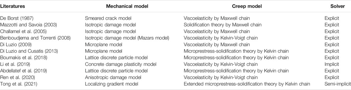
TABLE 1. Existing researches for the time-dependent damage analyses of concrete structures.
Although exhibiting apparent advantages, the above literatures still have limitation in the numerical analyses, as follows:
• Most of the above analyses are implemented with explicit finite element (FE) solver, and the computational cost is prohibitively high for long-term analyses of large-scale structures.
• The softening behavior of concrete is not properly regularized, and, therewith, it would lead to unrealistic results due to mesh-sensitivity problem (Peerlings et al. 1996).
• Most of creep models in the above analyses adopt empirical formulas in specifications and cannot reflect the real environmental conditions, of which varying temperature or humidity cannot be ignored.
It is acknowledged that the continuum-based constitutive law is easy to implement and is appropriate for large-scale concrete structures, especially with implicit finite element (FE) solver (Tong et al., 2016). Nevertheless, coupling concrete cracking with time-dependent behaviors is a nontrivial task. Strain softening in quasibrittle materials is the dilemma that has to been properly treated (Peerlings et al., 1996), which leads to loss of ellipticity of the differential equations and also the so-called mesh-dependent solutions upon element size. A series of regularization methods are continuously proposed targeting for mesh-objective simulations, i.e., the introduction of nonlocality in the constitutive model in either integral forms (Bažant et al., 1984), or gradient-enhanced damage (GED) forms (Schreyer and Chen, 1986; Peerlings et al., 1998; Poh and Sun, 2017), and the so-called phase-field approach (Kou et al., 2019; Li et al., 2020), although the integral-type forms are the most straightforward to implement the nonlocal theory in the FE model. The difficulty in deriving the tangent modulus at the element level prohibits the implicit FE solver and can only rely on the explicit FE solver (Bažant et al., 1984). Among them, the phase-field approach to the progressive events of brittle and quasibrittle fracture is proven to capture all stages of fracture, such as crack nucleation, initiation, propagation, and coalescence (Tanne et al., 2017). However, the computational cost of the phase field approach is prohibitively high and is not suitable for structural analyses hitherto. In this study, the GED model incorporating the high-order deformation terms is utilized. It is admitted that many efforts are made continuously to improve the original one proposed by Peerlings et al. (1996), i.e., the localizing GED model (Poh and Sun 2017) and stress-based GED model (Vandoren and Simone 2018). These improvements effectively overcome the spurious damage growth of the original GED model at large tensile strain. However, the selection of GED models is out of the scope of this study. We deliberatively select the original GED model in Peerlings et al. (1996) as its FE implementation is more easy compared to other GED models.
The proposed framework (termed as “GED-MPS” model hereafter) integrates the GED model for concrete′s mechanical behaviors with the MPS theory describing concrete’s creep behaviors. The model is implemented within the general FE software Abaqus/Standard with the implicit solver. In detail, Sect-2 introduces the theoretical background and computational framework of the GED-MPS model. Sect-3 illustrates the FE implementation of the model within Abaqus/Standard with implicit solver. Sect-4 reveals that the model can obtain mesh-objective solutions, not only for mechanical responses but creep deformations intertwined with concrete damage and cracking. Sect-5 validates the proposed model with the experiments by Gilbert and Nejadi (2004), who recorded the long-term deflections and cracking of a series of simply-supported reinforced concrete beams. Finally, conclusions are derived in Sect-6. To facilitate potential researchers and users, parts of the code and the input file are released at https://github.com/TengTongSEU/Coupled-creep-damage.
Constitutive Modeling Frameworks
Thermo-Hydro-Mechanical Coupling for Concrete
The GED-MPS model takes an engineering approach to the coupled time-dependent and mechanical behaviors of concrete, aiming to describe the most important aspects with sufficient accuracy at an affordable computational cost. Complete constitutive law of the GED-MPS model follows a rheological representation, as shown in Figure 1, which consists of
• a nonaging spring unit representing instantaneous elastic strain tensor
• a damage unit with the strain tensor
• a solidifying kelvin chain unit with typically more than ten elements in series representing the viscoelastic response with aging effect
• a dashpot unit with viscosity dependent on microprestress
• a shrinkage unit for strain tensor
• a thermal unit for strain tensor
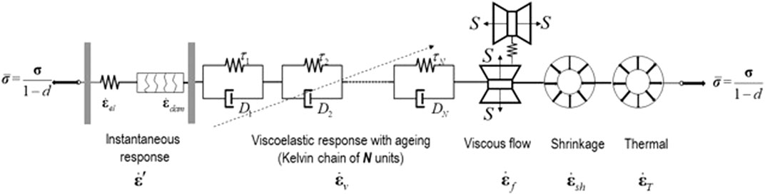
FIGURE 1. Rheological model for coupling in the GED-MPS model.
These units are connected in series, with the identical stress tensor
Concrete is interpreted as a composite material in which the coarse aggregates are embedded as inclusions in cement paste. Aging creep occurs exclusively in cement paste, whereas aggregates behave elastically. To capture the mesoscale behaviors of concrete creep in a more realistic manner, multiscale approaches and more sophisticated micromechanical models are necessary, which require more parameters and detailed information on the individual phases (Pichler et al., 2007; Scheiner and Hellmich 2009).
Theoretically, time-dependent evolutions of all relevant material properties should be taken into account to achieve an accurate damage process, i.e., creep and mechanical properties. Nevertheless, the loading of concrete structures at a very early-stage is not the focus of this study. Therewith, the mechanical properties of mature concrete are assumed to be constant, i.e., tensile strength or fracture energy. Their changes with concrete aging are ignored in this work. The multidecade prediction will provide conservative estimations as the slight increase in the mature concrete’s mechanical properties is not considered. The local age-dependent fracture properties should be enriched for the framework for concrete structures subject to early-age loadings.
Creep Evaluation by Microprestress-Solidification Theory
To predict creep deformations, semiempirical models are generally adopted by the engineering community, i.e., ACI, B3/B4, and CEB-FIP models. Numerous material properties act as input variables for these models, i.e., compressive strength, water to cement ratio, cement content, temperature, humidity, etc. Afterward, these engineering creep models predict the time-dependent deformation on a cross-sectional level in accumulated form (Boumakis et al., 2018).
Concrete creep can be mainly categorized into the aging of concrete, drying creep (Pickett effect), and transitional thermal creep (Bažant and Jirásek 2018). Bažant et al. (1997a,b) and assume that the continuous formation of C-S-H gels is responsible for the aging of concrete, including short-term chemical aging and long-term nonchemical aging. The first two creep sources, namely concrete aging and drying creep, can be formulated in the B4 model (Hubler et al., 2015), as the compliance function
where
Note that all the empirical models often yield the predictions far away from the measured responses, which can be attributed to the intrinsic heterogeneity of concrete and the variability in mix designs and environmental conditions. On the other hand, these engineering models lack the capacity to accurately predict the local point-wise response at varying stress/strain, local temperature, moisture content, and curing degree. To this end, the MPS theory is employed to describe the concrete’s time-dependent behaviors.
Solidification Theory for Aging Viscoelasticity in a Rate-Type Formulation
Concrete creep is found to follow the rules of aging linear viscoelasticity (Bažant et al., 2012a; Bažant et al.,2012b), within the service stress range (
A rate-type formulation can overcome these obstacles. In the rate-type approach, the previous history can be fully represented by internal variables only in the last time step (Yu et al., 2012). Rheological model is popularly adopted for rate-type concrete creep (Jirásek and Havlásek 2014; Yu et al., 2012). To this end, A K chain is employed herein, consisting of more than 10 K units, of distinctive modulus
where
with
which corresponds to a discrete Kelvin chain and is required for numerical computations. The exponential algorithm is generally adopted to quantify the time increment
Utilizing the Kelvin units, one can express the effective incremental modulus
where
Finally, the solidifying Kelvin chain gives the short-term creep strain tensor rate
where
with the rate-type formulation at hand, the values of
Microprestress Theory for Viscous Flow
The rate of viscous strain tensor
Under standard conditions (i.e., room temperature and sealed specimens), all the three time scales, namely
where
The bonds across the slip plane representing the nanopore filled with hindered adsorbed water are subject to two stresses: the macroscopic applied stress
where the effective viscosity
The source of
with
in which
where
By assuming that the evolution of viscosity should be the same as in model B4, the initial condition for differential Eq. 17 can be simply postulated as
where
Damage Evaluation by Gradient-Enhanced Damage Model
Local Damage Model
With the assistance of the effective stress concept (Rokhgireh and Nayebi 2019), the stress-strain relation of quasibrittle materials can be expressed as
where
To describe the damage evolution, the local scalar-valued equivalent strain
The loading function
The loading function
The history variable
Nonlocal Gradient-Enhanced Formulations
In a conventional local damage model,
where
By integrating the averaging partial differential equation Eq. 25 over the entire domain and adopting Gauss’ divergence theorem on the term
where
To guarantee that the average of
is adopted, resulting in the vanishment of the second term in the left-hand side of Eq. 26.
Damage Evolution
Two relations should be well defined to characterize the macroscopic stress-strain behavior: the evolution law of damage
where
The local equivalent strain
where
Coupling Damage and Creep
To describe the nonlinear concrete time-dependent behavior, a stress-strain law based on the rate independent isotropic damage model is formulated in Eq. 20, which can be interpreted as Hooke’s law linking the strain to the effective stress tensor
The above equation indicates the stress transmitted by the undamaged continuous solid material, which would be
Finite Element Formulation
Governing Equations and FE Discretization
The model presented in this work is discretized using a Galerkin FE approach. Strong forms of governing equations for the GED-MPS model for quasistatic problems are
where
These equations are supplemented by the following Neumann and Dirichlet boundary conditions:
where
In the FE implementation, the displacement field
with ṵ and
To construct a consistent incremental-iterative Newton-Raphson solution procedure, Eqs 38, 39 have to be linearized. The linearization at iteration
Of special attention is that the components in the stiffness matrix and the right-hand side vector depend on the
and the subvectors in the right-hand sides are defined as
Note that the element stiffness matrix becomes nonsymmetric since
Creep Strain Tensors
The key parameter in implementing the GED-MPS model is to obtain the local equivalent strain field
The aforementioned rate-type formulation can be used for the basic creep compliance
where reduced time
As a consequence, the exponential algorithm following the procedures can be implemented to obtain the increment of aging viscoelasticity
1) At
2) Let
with
3) Discretize the spectrum using
4) Calculate
5) Obtain increment of aging viscoelasticity
6) After retrieving the stress increment
7) Begin the next time step.
Now we turn to the increment of viscous flow
1) The temperature and humidity of the previous time step
with
2) Suppose
For the creep deformation coupled with concrete damage or cracking, the nominal stress tensor
Implementation Aspects in Abaqus
The system of equations above is highly nonlinear. To implement the model with implicit FE solver, the general FE software Abaqus/Standard is selected for its built-in implicit incremental-iterative Newton-Raphson algorithm and automatic time-step-ping schemes. The user-defined element (UEL) subroutine enables us to define the element, of which computation of element tangent stiffness and nodal force vectors is realized.
Plane stress is taken into account in the following simulations. To guarantee the consistency requirements, the shape functions and their derivatives for the displacement field
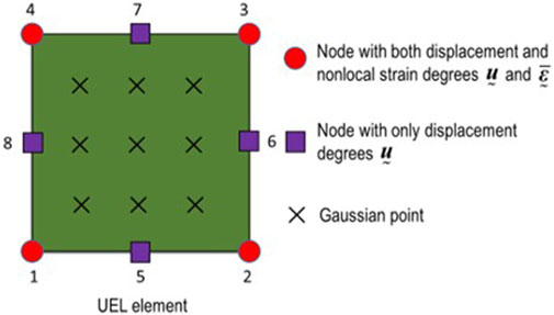
FIGURE 2. Degrees of freedom of 2D element for the GED-MPS model.
The corresponding shape functions and their derivatives are
and
It is noteworthy that the analysis with UEL subroutine is inconvenient in the postprocessing and visualization of the results. Because shape functions are defined by users in the UEL subroutine, the Abaqus cannot extrapolate variables from Gauss points to the element nodes, automatically. To this end, an auxiliary dummy mesh is adopted, consisting of standard Abaqus elements that resemble the UEL elements in terms of number of nodes and integration points. The material response at each integration point in the auxiliary mesh is defined using a user material subroutine (UMAT), which enables the user to define the constitutive matrix and stresses from the strain values.
In this auxiliary mesh, the stress components are deliberatively set as zero so as not to influence the global solution. The data from the UEL for each time increment we want to observe in Abaqus/Viewer is stored as built-in array SVARS, which allows transferring to the UMAT subroutine by the built-in array STATEV for each corresponding element and integration point. Transferring of values from SVARS array to STATEV array is accomplished by making use of the common statement (Msekh et al., 2015). Figure 3 shows the technique to implement the visualization of the analyses with the UEL subroutines.
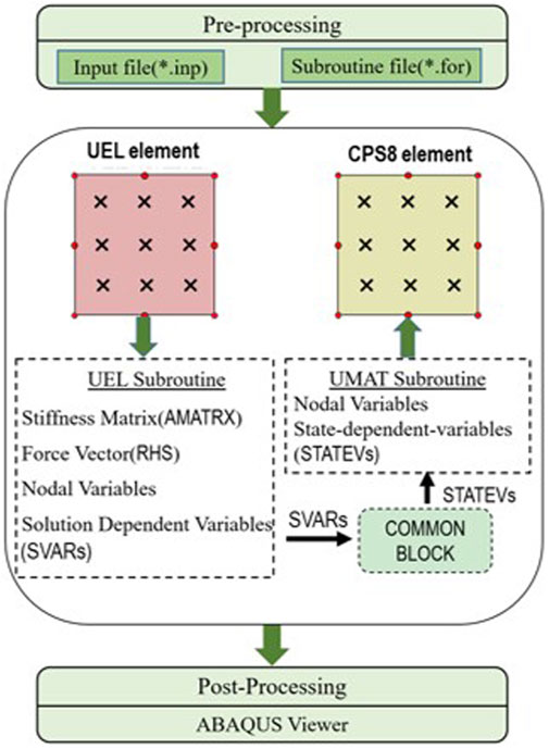
FIGURE 3. Layered system of the FE elements and data flow in Abaqus with UEL and UMAT.
Illustration of GED-MPS Model
A 100 mm long bar is taken for an illustration, which is subject to uniaxial tensile loading. The Young’s modulus is deliberatively reduced by 5% in a 10 mm wide zone in the middle of the bar to trigger localization of deformation. The following mechanical parameters are set for this illustration, with
The first group of analyses embraces the bar discretized with 80 elements, but with three different values of gradient parameter

FIGURE 4. Damage and normalized stress-strain curves for the simulations of different c.
The second group of analyses embraces the bar discretized with different element size, but with identical gradient parameter
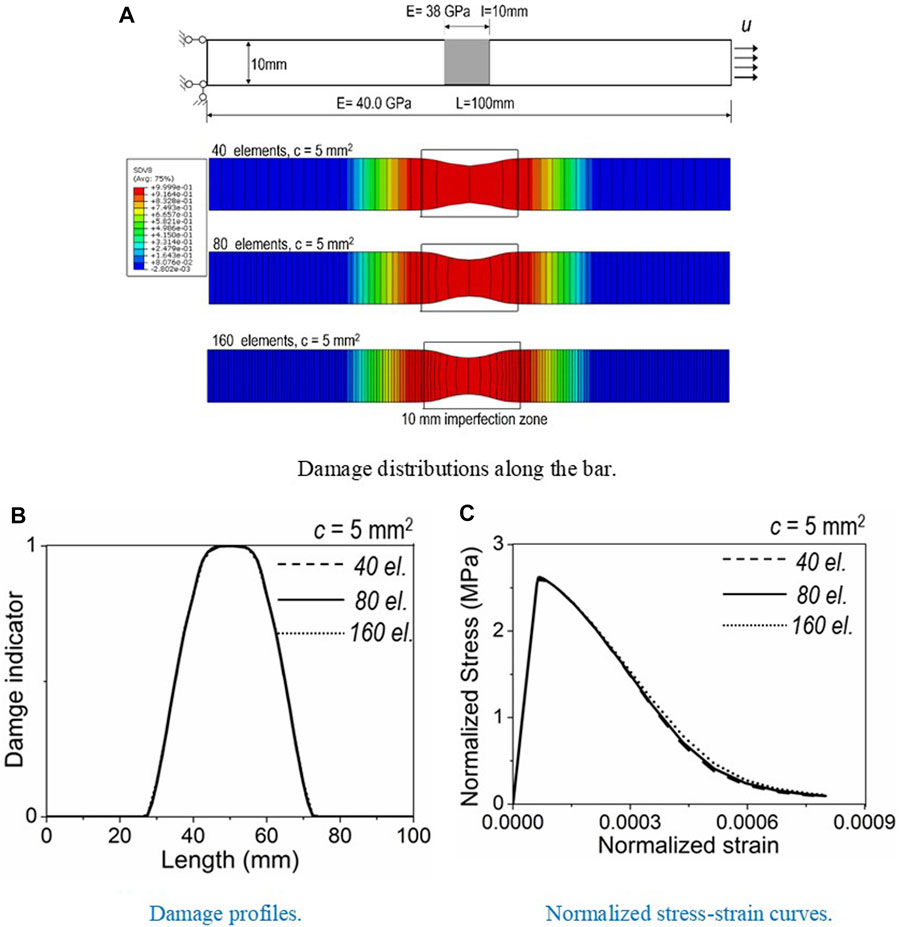
FIGURE 5. Damage and normalized stress-strain curves for the simulations of different element size.
Figure 5 clearly shows that mesh-dependent solutions of mechanical responses of quasibrittle materials are regularized by the GED model, without creep deformation. However, limited literatures report the mesh-sensitivity problem in the time-dependent analyses of quasibrittle materials, especially when coupled with cracking, according to the authors’ knowledge. Intuitively, mesh-sensitivity solution is a concern, as the creep depends on the stress tensor and the damage state at each material point.
To this end, the proposed GED-MPS model is applied to the same bar. The external loading is applied at the bar’s right end at the day of
Similarly, the first group of analyses embraces the bar discretized with identical 80 elements, but with different gradient parameters as
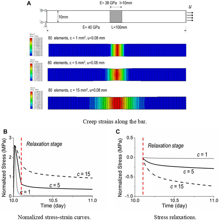
FIGURE 6. Simulations of creep behaviors intertwined with damage with different c.
Alongside, effects of gradient parameters
Calibration With Tests of Simply-Supported Concrete Beams
Engineering community concerns more about long-term deflections of reinforced concrete or prestressed concrete structures, coupled to concrete cracking. In this section, the capability of the GED-MPS model is further extended to the reinforced concrete structures. Long-term tests of simply-supported reinforced concrete beams in Gilbert and Nejadi (2004) are simulated.
Although totally 6 beams and 6 slabs were reported, this paper selected two typical specimens for simulations, namely specimens B2-a and B2-b. These two specimens owned a 250 × 340 rectangular cross-section and 3,500 mm in length. The concrete cover thickness is 25 mm. Two 16 mm diameter rebars were arranged as the flexural reinforcement. During the test, these two specimens were loaded to 50% (specimen B2-a) and 30% (specimen B2-b) of their flexural strengths, respectively. A constant external loading was applied on the concrete specimens. This loading test began at 14 days and lasted for around 400 days. Concrete properties were measured at different ages and they are summarized in Table 2.

TABLE 2. Concrete properties at different ages.
Creep Calibrations
The concrete creep and shrinkage tests were provided in Gilbert and Nejadi (2004), which begun at the 14-day concrete age. No data is provided regarding temperature and humidity, and they are set as
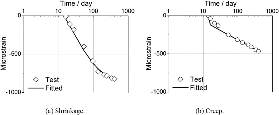
FIGURE 7. Experimental data and numerical fitting for concrete shrinkage and creep.
With respect to parameters for concrete creep, the following creep parameters are selected to fit the experimental creep data, with
Long-Term Deflections and Cracking Distributions
The GED-MPS model is verified with experimental data of specimens B2-a and B2-b, which were subject to external loading of 18.6 and 11.7 kN, respectively. The identical calibrated parameters listed in Sect-5.1 are utilized without any modification. Some artificial defects were deliberatively introduced at the bottoms of FE models to trigger the cracks.
ffects of different gradient parameter
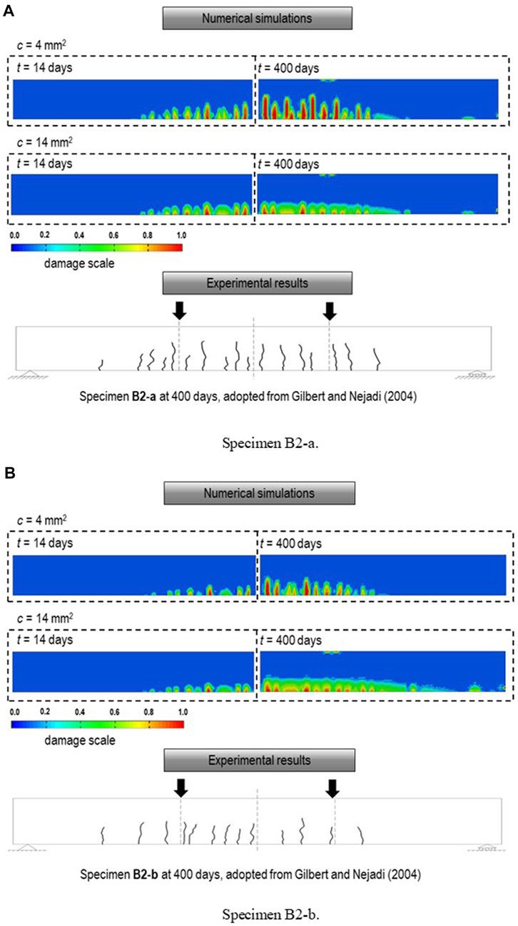
FIGURE 8. Experimental and numerical crack profiles.
Long-term vertical deflections of Specimen B2-a with different
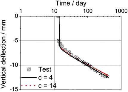
FIGURE 9. Experimental and numerical deflections of specimen B2-a with different c.
Furthermore, conventional linear viscoelastic analysis considering only creep and shrinkage deformations, without intertwined effect with concrete damage and cracking (termed as MPS in Figure 10), is compared to the GED-MPS model in Figure 10A for specimens B2-a and Figure 10B for specimen B2-b. Clearly, conventional linear viscoelastic analysis underestimates their long-term vertical deflections, which can be satisfactorily remedied by the GED-MPS model.
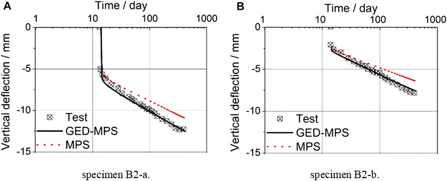
FIGURE 10. Experimental and numerical deflections w/wo concrete cracking.
Considering the effect of different temperatures on the long-term deflection of these specimens, four different temperatures are selected, and they are
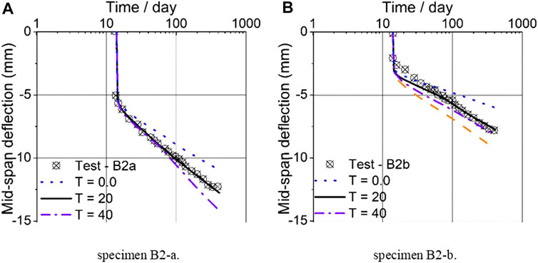
FIGURE 11. Mid-span deflection curves at various temperatures.
The effects of different humidity on long-term deflection of specimens B2-a and B2-b are further revealed in Figure 12, with different humidity of
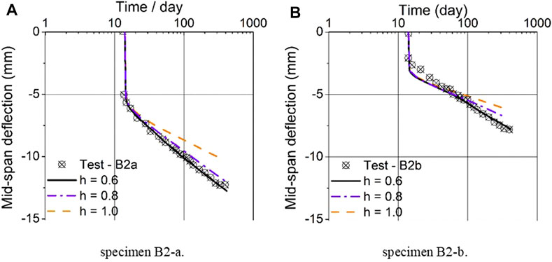
FIGURE 12. Mid-span deflection curves at various humidity.
Conclusion
The GED-MPS model is proposed and implemented with implicit FE software Abaqus/Standard. The model integrates the GED model capable of circumventing the mesh-sensitivity in the conventional mechanical analyses for quasibrittle materials exhibiting strain softening behaviors, and the MPS theory capable of predicting point-wise creep responses.
The GED-MPS model anchors at the rate-type formulation, and, therefore, is capable of incorporating other memory-dependent processes. After being enriched with continuous spectrum method and exponential algorithm, the model is efficient and stable for large-scale structural analysis. The model successfully regularizes the mesh-sensitivity problem, which is already concerned with mechanical analyses of materials exhibiting softening, but less with the nonlinear creep intertwined with cracking. The GED-MPS model is applied to simply supported reinforced concrete beams. It is proven that the proposed model is capable of capturing not only the long-term vertical deflection trends, but also the time-dependent cracking propagations affected by creep and shrinkage.
Further improvements to polish the model could be conducted, i.e., implementing more accurate anisotropic constitutive model for concrete, instead of the isotropic one, replacing the current GED model with stress-based GED model to address the issue of spurious damage growth. With the GED-MPS model being implemented in the implicit FE algorithm, authors are expected to extend this model to accurately predict long-term behaviors of real large-scale creep-sensitive structures.
Data Availability Statement
The raw data supporting the conclusion of this article will be made available by the authors, without undue reservation. To facilitate potential researchers and users, parts of the code and the input file are released at https://github.com/TengTongSEU/Coupled-creepdamage.
Author Contributions
TT: Conceptualization, Methodology, Writing-Original draft preparation. CD: Conceptualization, Supervision. XL: Methodology, Writing- Reviewing and Editing. SY: Conceptualization, Supervision, Writing- Reviewing and Editing. ZL: Supervision, Writing- Reviewing and Editing.
Funding
This research is supported by the National Key Research and Development Program of China (2019YFE0119800), the National Natural Science Foundation for Young Scientists of China (51808113), the National Natural Science Foundation for Young Scientists of Jiangsu Province (BK20180389), and the Zhishan Youth Scholar Program of SEU.
Conflict of Interest
CD and XL were employed by the company State Gird Jiangsu Electric Power Engineering Consulting Co. Ltd.
The remaining authors declare that the research was conducted in the absence of any commercial or financial relationships that could be construed as a potential conflict of interest.
Publisher’s Note
All claims expressed in this article are solely those of the authors and do not necessarily represent those of their affiliated organizations, or those of the publisher, the editors, and the reviewers. Any product that may be evaluated in this article, or claim that may be made by its manufacturer, is not guaranteed or endorsed by the publisher.
References
Abdellatef, M., Boumakis, I., Wan-Wendner, R., and Alnaggar, M. (2019). Lattice Discrete Particle Modeling of Concrete Coupled Creep and Shrinkage Behavior: A Comprehensive Calibration and Validation Study. Construction Building Mater. 211, 629–645. doi:10.1016/j.conbuildmat.2019.03.176
ACI Committee 209 (2008). Guide for Modeling and Calculating Shrinkage and Creep in Hardened concrete. ACI. 209, 2.R-08
Bažant, Z. P. (1971). Numerically Stable Algorithm with Increasing Time Steps for Integral-type Aging Creep. Proc. 1st Int. Conf. Struct. Mech. Reactor Tech.
Bažant, Z. P., and Li, G. H. (2008). Comprehensive Database on Concrete Creep and Shrinkage. ACI Mater. J. 105 (6), 635–637.
Bažant, Z. P., Belytschko, T. B., and Chang, T. P. (1984). Continuum Theory for Strain-Softening. J. Eng. Mech-asce. 110 (12), 1666–1692. doi:10.1061/(ASCE)0733-9399(1984)110:12(1666)
Bažant, Z. P., Hauggaard, A. B., Baweja, S., and Ulm, F. J. (1997a). Microprestress-Solidification Theory for concrete Creep. I: Aging and Drying Effects. J. Eng. Mech-asce. 123 (11), 1188–1194. doi:10.1061/(ASCE)0733-9399(1997)123:11(1188)
Bažant, Z. P., Hauggaard, A. B., and Baweja, S. (1997b). Microprestress-Solidification Theory for Concrete Creep. II: Algorithm and Verification. J. Eng. Mech-asce. 123 (11), 1195–1201. doi:10.1061/(ASCE)0733-9399(1997)123:11(1195)
Bažant, Z. P., and Jirásek, M. (2018). Creep and Hygrothermal Effects in concrete Structures. Basingstoke, UK: Springer, Vol. 225
Bažant, Z. P., and Xi, Y. (1995). Continuous Retardation Spectrum for Solidification Theory of Concrete Creep. J. Eng. Mech-asce. 121 (2), 281–288. doi:10.1061/(ASCE)0733-9399(1995)121:2(281)
Bažant, Z. P., Yu, Q., and Li, G. H. (2012a). Excessive Long-Time Deflections of Prestressed Box Girders. I: Record-Span Bridge in Palau and Other Paradigms. J. Struct. Eng-asce. 138 (6), 676–686. doi:10.1061/(ASCE)ST.1943-541X.0000487
Bažant, Z. P., Yu, Q., and Li, G. H. (2012b). Excessive Long-Time Deflections of Prestressed Box Girders. II: Numerical Analysis and Lessons Learned. J. Eng. Mech-asce. 138 (6), 687–696. doi:10.1061/(ASCE)ST.1943-541X.0000375
Benboudjema, F., and Torrenti, J. M. (2008). Early-age Behaviour of Concrete Nuclear Containments. Nucl. Eng. Des. 238 (10), 2495–2506. doi:10.1016/j.nucengdes.2008.04.009
Boumakis, I., Di Luzio, G., Marcon, M., Vorel, J., and Wan-Wendner, R. (2018). Discrete Element Framework for Modeling Tertiary Creep of Concrete in Tension and Compression. Eng. Fracture Mech. 200, 263–282. doi:10.1016/j.engfracmech.2018.07.006
Challamel, N., Lanos, C., and Casandjian, C. (2005). Creep Damage Modelling for Quasi-Brittle Materials. Eur. J. Mech. A - Solids. 24 (4), 593–613. doi:10.1016/j.euromechsol.2005.05.003
De Borst, R. (1987). Smeared Cracking, Plasticity, Creep, and thermal Loading-A Unified Approach. Computer Methods Appl. Mech. Eng. 62 (1), 89–110. doi:10.1016/0045-7825(87)90091-0
De Borst, R., and Verhoosel, C. V. (2016). Gradient Damage vs Phase-Field Approaches for Fracture: Similarities and Differences. Computer Methods Appl. Mech. Eng. 312, 78–94. doi:10.1016/j.cma.2016.05.015
Di Luzio, G., and Cusatis, G. (2013). Solidification-Microprestress-Microplane (SMM) Theory for concrete at Early Age: Theory, Validation and Application. Int. J. Sol. Structures. 50 (6), 957–975. doi:10.1016/j.ijsolstr.2012.11.022
Di Luzio, G. (2009). Numerical Model for Time-Dependent Fracturing of concrete. J. Eng. Mech. 135 (7), 632–640. doi:10.1061/(asce)0733-9399(2009)135:7(632)
Gilbert, R. I., and Nejadi, S. (2004). An Experimental Study of Flexural Cracking in Reinforced concrete Members under Short Term Loads. Sydney, NSW, Australia: School of Civil and Environmental Engineering. University of New South Wales.
Hubler, M. H., Wendner, R., and Bažant, Z. P. (2015). Statistical Justification of Model B4 for Drying and Autogenous Shrinkage of Concrete and Comparisons to Other Models. Mater. Struct. 48 (4), 797–814. doi:10.1617/s11527-014-0516-z
Jirásek, M., and Havlásek, P. (2014). Microprestress-Solidification Theory of Concrete Creep: Reformulation and Improvement. Cement Concrete Res. 60, 51–62. doi:10.1016/j.cemconres.2014.03.008
Kou, M. M., Lian, Y. J., and Wang, Y. T. (2019). Numerical Investigations on Crack Propagation and Crack Branching in Brittle Solids under Dynamic Loading Using Bond-Particle Model. Eng. Fracture Mech. 212, 41–56. doi:10.1016/j.engfracmech.2019.03.012
Li, G., Yin, B. B., Zhang, L. W., and Liew, K. M. (2020). Modeling Microfracture Evolution in Heterogeneous Composites: A Coupled Cohesive Phase-Field Model. J. Mech. Phys. Sol. 142, 103968. doi:10.1016/j.jmps.2020.103968
Li, S., Yang, Y., Pu, Q., Yang, D., Sun, B., and Li, X. (2019). Three‐dimensional Nonlinear Creep and Shrinkage Effects of a Long‐Span Prestressed concrete Box Girder Bridge. Struct. Concrete. 20 (2), 638–649. doi:10.1002/suco.201800148
Mazzotti, C., and Savoia, M. (2003). Nonlinear Creep Damage Model for Concrete Under Uniaxial Compression. J. Eng. Mech. 129 (9), 1065–1075. doi:10.1061/(asce)0733-9399(2003)129:9(1065)
Mei, S., and Wang, Y. (2020). Viscoelasticity: A New Perspective on Correlation Between Concrete Creep and Damping. Construction Building Mater. 265, 120557. doi:10.1016/j.conbuildmat.2020.120557
Msekh, M. A., Sargado, J. M., Jamshidian, M., Areias, P. M., and Rabczuk, T. (2015). Abaqus Implementation of Phase-Field Model for Brittle Fracture. Comput. Mater. Sci. 96, 472–484. doi:10.1016/j.commatsci.2014.05.071
Peerlings, R. H. J., De Borst, R., Brekelmans, W. A. M., and De Vree, J. H. P. (1996). Gradient Enhanced Damage for Quasi-Brittle Materials. Int. J. Numer. Meth. Engng. 39 (19), 3391–3403. doi:10.1002/(sici)1097-0207(19961015)39:19<3391::aid-nme7>3.0.co;2-d
Peerlings, R. H. J., De Borst, R., Brekelmans, W. A. M., and Geers, M. G. D. (1998). Gradient-Enhanced Damage Modelling of concrete Fracture. Mech. Cohes.-Frict. Mater. 3 (4), 323–342. doi:10.1002/(sici)1099-1484(1998100)3:4<323::aid-cfm51>3.0.co;2-z
Pichler, C., Lackner, R., and Mang, H. A. (2007). A Multiscale Micromechanics Model for the Autogenous-Shrinkage Deformation of Early-Age Cement-Based Materials. Eng. Fract. Mech. 74 (1-2), 34–58. doi:10.1016/j.engfracmech.2006.01.034
Poh, L. H., and Sun, G. (2017). Localizing Gradient Damage Model With Decreasing Interactions. Int. J. Numer. Meth. Engng. 110 (6), 503–522. doi:10.1002/nme.5364
Rahimi-Aghdam, S., Bažant, Z. P., and Cusatis, G. (2019). Extended Microprestress-Solidification Theory for Long-Term Creep With Diffusion Size Effect in Concrete at Variable Environment. J. Eng. Mech. 145 (2), 04018131. doi:10.1061/(asce)em.1943-7889.0001559
Ren, J., Wang, J., Li, X., Wei, K., Li, H., and Deng, S. (2020). Influence of Cement Asphalt Mortar Debonding on the Damage Distribution and Mechanical Responses of CRTS I Prefabricated Slab. Construction Building Mater. 230, 116995. doi:10.1016/j.conbuildmat.2019.116995
Rokhgireh, H., and Nayebi, A. (2019). Non-proportional Stress and Stress-Strain Controlled Paths Cyclic Loading Modeling by Using Anisotropic Continuum Damage Model. Theor. Appl. Fracture Mech. 103, 102311. doi:10.1016/j.tafmec.2019.102311
Sarkar, S., Singh, I. V., Mishra, B. K., Shedbale, A. S., and Poh, L. H. (2019). A Comparative Study and ABAQUS Implementation of Conventional and Localizing Gradient Enhanced Damage Models. Finite Elem. Anal. Des. 160, 1–31. doi:10.1016/j.finel.2019.04.001
Scheiner, S., and Hellmich, C. (2009). Continuum Microviscoelasticity Model for Aging Basic Creep of Early-Age concrete. J. Eng. Mech. 135 (4), 307–323. doi:10.1061/(asce)0733-9399(2009)135:4(307)
Schlappal, T., Kalliauer, J., Vill, M., Gmainer, S., Mang, H. A., Eberhardsteiner, J., et al. (2020). Serviceability Limits of Reinforced Concrete Hinges. Eng. Structures. 208, 109861. doi:10.1016/j.engstruct.2019.109861
Schreyer, H. L., and Chen, Z. (1986). One-dimensional Softening with Localization. J. Appl. Mech. 53 (4), 791–797. doi:10.1115/1.3171860
Tanne, E., Li, T., and Bourdin, B. (2017). Crack Nucleation in Variational Phase-Field Models of Brittle Fracture. J. Mech. Phys. Sol. 110, 80–99. doi:10.1016/j.jmps.2017.09.006
Tong, T., Hua, G., Liu, Z., Liu, X., and Xu, T. (2021). Localizing Gradient Damage Model Coupled to Extended Microprestress-Solidification Theory for Long-Term Nonlinear Time-dependent Behaviors of Concrete Structures. Mech. Mater. 154, 103713. doi:10.1016/j.mechmat.2020.103713
Tong, T., Liu, Z., Zhang, J., and Yu, Q. (2016). Long-Term Performance of Prestressed Concrete Bridges Under the Intertwined Effects of concrete Damage, Static Creep and Traffic-Induced Cyclic Creep. Eng. Structures. 127, 510–524. doi:10.1016/j.engstruct.2016.09.004
Vandoren, B., and Simone, A. (2018). Modeling and Simulation of Quasi-Brittle Failure With Continuous Anisotropic Stress-Based Gradient-Enhanced Damage Models. Computer Methods Appl. Mech. Eng. 332, 644–685. doi:10.1016/j.cma.2017.12.027
Vogler, M., Rolfes, R., and Camanho, P. P. (2013). Modeling the Inelastic Deformation and Fracture of Polymer Composites - Part I: Plasticity Model. Mech. Mater. 59, 50–64. doi:10.1016/j.mechmat.2012.12.002
Widder, D. V. (1971). An Introduction to Transform. Cambridge, Massachusetts: Academic Press, Vol. 42
Yu, Q., Bažant, Z. P., and Wendner, R. (2012). Improved Algorithm for Efficient and Realistic Creep Analysis of Large Creep-Sensitive concrete Structures. ACI Struct. J. 109 (5), 665.
Nomenclature
Keywords: nonlinear creep, nonlocal, microprestress, solidification, time-dependent
Citation: Tong T, Du C, Liu X, Yuan S and Liu Z (2021) Gradient Nonlocal Enhanced Microprestress-Solidification Theory and Its Finite Element Implementation. Front. Mater. 8:701458. doi: 10.3389/fmats.2021.701458
Received: 30 April 2021; Accepted: 21 July 2021;
Published: 30 August 2021.
Edited by:
Ramadhansyah Putra Jaya, Universiti Malaysia Pahang, MalaysiaReviewed by:
Nor Hasanah Abdul Shukor Lim, Universiti Teknologi Malaysia, MalaysiaAhmad Razin Zainal Abidin, University of Technology Malaysia, Malaysia
Copyright © 2021 Tong, Du, Liu, Yuan and Liu. This is an open-access article distributed under the terms of the Creative Commons Attribution License (CC BY). The use, distribution or reproduction in other forums is permitted, provided the original author(s) and the copyright owner(s) are credited and that the original publication in this journal is cited, in accordance with accepted academic practice. No use, distribution or reproduction is permitted which does not comply with these terms.
*Correspondence: Teng Tong, dGVuZ3RvbmdAc2V1LmVkdS5jbg==; Changqing Du, ZHVjaGFuZ3FpbmcxOTg0QDE2My5jb20=