 Hongbiao Liu
 Baohua Zhang1*
- 1National Engineering Laboratory for Port Hydraulic Construction Technology, Tianjin Research Institute of Water Transport Engineering, Tianjin, China
- 2Department of Civil Engineering, Tianjin Chengjian University, Tianjin, China
The structural durability monitoring (SDM) system for a high-piled wharf in the Tianjin Port of China is devised and deployed with an anode ladder sensor, which provides a means to monitor the state of steel corrosion for the wharf. In this project, the anode-ladder sensors are installed on the reinforced concrete components of the front platforms. After the installation, the monitoring data from the anode-ladder sensor was collected for 40 months. Based on the monitoring data for 40 months, it is proven that the resistance of concrete will be significantly affected by the change in temperature, and the increase in temperature will cause the drop in concrete resistance. Furthermore, the data of the anode-ladder sensor set in the track beam of the front platform shows that the current in anode A1 and A2 relative to the cathode exceeded 15 μA during the four-month period, which is abnormal. The main reason is the influence of concrete temperature and humidity. Therefore, the monitoring data for current, voltage, resistance, and temperature should be combined to determine the activation state of the anode, and cannot be determined simply using the current value.
Introduction
Corrosion of the reinforcing steel in concrete induced by chloride-ion penetration and carbonation of concrete cause serious damage to concrete structures exposed to aggressive environments, e.g., the chloride-induced corrosion of reinforcement in concrete structures in tidal zones and coastal areas (Kassiret et al., 2002; Pech-Canul et al., 2002). A large number of harbor structures like wharves, harbor bridges, piers, dams, and other harbor structures are attacked severely the penetration of chloride ions from seawater, which caused many of them to be repaired or replaced (Melchers et al., 2006). As a result, repair costs nowadays constitute a major part of the maintenance spending on the harbor structures.
In reinforced concrete structures such as wharves and sea-crossing bridges in marine environments, concrete cracking caused by the corrosion of the reinforcement in concrete induced by chlorides is more serious than carbonization of the concrete. Chloride-penetration causes faster rusting of the reinforcement and makes increases the loss, which is the main factor that affects the durability of concrete structures in the marine environment and has been paid extensive attention by those in engineering and academia. The typical damage to reinforced concrete structures in harbors caused by chloride penetration is shown in Figure 1.
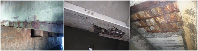
FIGURE 1. Typical durability damage of harbor structures induced by chlorides.
Despite the considerable loss caused by the chloride-induced corrosion in such structures, more and more of these are being built, which are also required to have a service life of 100 years or more, such as China’s Hong Kong-Zhuhai-Macao bridge project and Hangzhou bay bridge. This necessitates more stringent requirements for the durability of reinforced concrete structures. However, there is no generally accepted reliability design theory available currently that can guarantee that the concrete structure can be used for 100 years or longer (Xu et al., 2013). Therefore, in order to achieve longer service life of the concrete structure, the principle of durability design and redesign is adopted, that is, the actual durability information of the concrete structure is obtained based on in-service monitoring of the concrete structure, and further measures are taken to ensure the durability requirements of concrete structures for those parts that do not meet the design requirements (Engelund et al., 2000; Tomosawa, 2009). Accordingly, it is necessary to collect durability data for the concrete structure by monitoring, and precautions can be taken before the commencement of the reinforcement corrosion process (Keddam et al., 1997; Raupach et al., 2001; McCarter et al., 2005) thus ensuring not only the durability requirements of the structure but also reducing the maintenance cost. As known, the costs for repair measures increase steeply with time, when the reinforcement has already started to corrode. The durability maintenance cost of the concrete structure meets the “five-fold law”, that is, the repair cost of the slight damage is five times the cost of the preventive measures. Therefore, it is very important to monitor the durability of concrete structures in the marine environment.
Thus, in the last few decades, significant effort has been put into the development of non-destructive testing as well as structural health monitoring tools and methods that are suitable for the objective assessment of concrete structures. A variety of non-destructive evaluation techniques and methods, such as ultrasonic testing, ground penetrating radar, and half-cell potential method were proposed, some of which have been applied widely for the detection of concrete structures (Arndt et al., 2011). However, traditional on-site inspection methods like reference cells only show the local onset of corrosion and not the time-to-corrosion, which is measurable using an anode-ladder sensor. Automatic monitoring using sensors is more cost-effective than the usual on-site inspections, especially in areas that are difficult to access. It enables operators to take protective measures before the damage is initiated.
The anode-ladder system has been used in several concrete structures worldwide, mainly bridges. However, research regarding the application of durability-monitoring of high-piled wharfs in the harbor. The wharf structure in coastal ports serve in seawater, where durability problems caused by chloride penetration is more prominent, making structural durability monitoring essential. The objective of this work is to devise and deploy an anode-ladder-based long-term durability monitoring system on a newly built high-piled wharf structure in the Tianjin port in China. The wharf named South 27# Wharf is 390 m long and 75 m wide, which will be used for ore transportation and other bulk cargo shipping. A structural health monitoring (SHM) system based on Fiber Bragg Grating (FBG) sensor techniques was used in the project. The primary function of the SHM system is the durability monitoring with the anode-ladder-system, which can collect the macrocell potential, current, resistance, and temperature of the reinforced concrete components to assess the corrosion risk of the structure. The installation and setup of anode-ladder sensors in the high-piled wharf are also described. The conclusion of this study is expected to aid the development of long-term health monitoring technology in coastal ports.
Theoretical Background
Corrosion Theory of Steel in Concrete
In general, reinforcing steel in the concrete has good corrosion resistance due to the highly alkaline environment in the concrete, which has pH values ranging from 12.5 to 13.5. In the high alkaline environment, a thin oxide layer called the passive film is formed at the surface of the reinforcement, which can protect the iron from dissolution to negligibly low values. Normally this passivity is stable during the entire service life of a reinforced concrete structure. However, a variety of causes, such as the chloride ion penetration or carbonization of concrete, can break the passive film formed on the rebar. As a result, the reinforcement will change from the passivated state to an activated state (i.e., depassivation). Then, the combination of available water, oxygen, and chloride ion with steel leads to the rusting of the reinforcement. With the gradual aggravation of reinforcement corrosion, the concrete cracks and spalls off due to rust expansion. Eventually, severe damage was detected in the concrete (Raupach, 1996).
The corrosion of steel is a complicated process and involves several steps. Finally, ferric hydroxide (Fe (OH)3) is formed, which transforms into hydrated ferric oxide Fe2O3, i.e., rust. The electrical and chemical reactions for the corrosion of steel are shown in Figure 2.
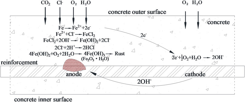
FIGURE 2. Representation of the corrosion process of rebar in concrete and the electrochemical reaction.
Carbonation of concrete is the chemical reaction of CO2 with the alkaline substances in the concrete pore solution, causing a reduction in the pH value to less than 10, and making it one of the reasons for the corrosion. However, the main cause of reinforcement corrosion in harbor reinforced concrete structures is the penetration of chloride ions based on the field inspection experience. Consequently, this work focuses only on chloride-induced corrosion. It can be seen from Figure 2 that chloride ion intrusion can also cause a decrease in the pH value. When a critical limit value of chloride content in the pore water solution is exceeded, the steel starts rusting.
Chloride-induced corrosion of steel in concrete is an electrochemical process analogous to the operation of a battery. Different surface areas of the reinforcement act as the anode or cathode of the battery, which are shown in Figure 2. At the anode, iron (Fe) loses electrons and becomes iron ions (Fe2+), which easily with chloride ions (Cl−) to form a FeCl2 solution, acting as a carrier of iron ions. It causes anode depolarization and accelerates the anodic reinforcement process. At the cathode, electrons, water, and oxygen are converted into hydroxyl ions (OH−). The cathodic process does not cause any deterioration of the steel. On the contrary, it protects the reinforcement, which is called cathodic protection. Then, hydroxyl ions (OH−) with the negatively charged ions move toward the anode from the cathode in the electrolyte based on the electrical field created between the anode and cathode. Near the anode, they react with the iron ions in the solution forming ferrous hydroxide [Fe(OH)2], and the chloride ions (Cl−) are released to repeat the process above. Subsequently, ferrous hydroxide [Fe(OH)2] reacts with oxygen (O2) and water (H2O) forming ferric hydroxide [Fe(OH)3] and finally, Fe2O3, which is the corrosion product (Arndt et al., 2011). Generally, the volume of the rust is 3–6 times than that of iron, causing concrete cracking and spalling off due to expansion when the rebar corrosion achieves a critical limit value.
This shows that the corrosion of reinforcement in harbor concrete structures is mainly caused by the harmful intrusion of chloride ions. Also, the depassivation threshold in the reinforcement is known as the frontal line of critical chloride ion concentration for harbor concrete structures exposed to seawater that is rich in chloride ions. Therefore, if the penetration behavior of chloride ions in concrete, such as the position of the frontal line of critical chloride ion concentration and its moving speed, can be collected suitably, the corrosion time of steel in concrete can be predicted. This results in a significant reduction of maintenance costs as repair costs increase steeply with time when the reinforcement has already started to corrode.
Development of the Anode-ladder Sensor
Based on the corrosion theory of concrete structures, Bashear (1996) proposed a concrete degradation model to predict the performance degradation of concrete structures, and emphasized the influence of permeability on concrete degradation (Basheer et al., 1996). Glass (2000) points out that the chloride-induced corrosion of rebar is the main factor that affects the durability of concrete structures (Glass et al., 2000). Ahmad (2003) summarized the mechanism of steel corrosion, monitoring technology of steel corrosion, and methods for predicting the remaining service life of structures using empirical model as well as experimentation. It is also pointed out that the main factor affecting the durability of reinforced concrete structures is chloride-induced corrosion (Ahmad, 2003). Even though many new systems and materials have been developed to repair the damage and increase durability, many monitoring systems do not resolve the time-to-corrosion problem. Therefore, the anode-ladder sensor, which can measure the time-to-corrosion data of reinforcement in concrete, was developed by Raupach in 1986 and successfully applied to the monitoring of steel corrosion in concrete structures in 1990, providing a technical means for the durability redesign of concrete structures (Raupach, 1996; Raupach, 2009). Raupach (2001) used the anode-ladder-system to monitor the permeation depth of chloride ions in concrete structures, and the corrosion state of steel could be predicted based on the monitoring data (Raupach et al., 2001). Subsequently, Zhang (2009), and Jin (2013) applied the anode-ladder-system to the underwater tunnel, wharf, and other hydraulic structures to monitor the durability of concrete structures (Zhang et al., 2009; Jin et al., 2013). The anode-ladder sensor is a kind of durability sensor which can determine the position of the depassivation threshold in the reinforcement. Therefore, it is very effective for monitoring the durability state of the coastal piled-wharf structure and predicting the corrosion time of steel bars in concrete.
The anode-ladder sensor for structural durability monitoring of the South 27# Wharf in Tianjin Port is manufactured in Germany. The anode-ladder-system includes the anode-ladder embedded in concrete, measuring cables, test boxes on the concrete surface and special reading meters for data collection. The sensor components are the anode-ladder, cathode, reference electrode, reinforcement connecting rod, and temperature probe (PT 1,000), which is shown in Figure 3. The anode-ladder has six black carbon steel anodes denoted as A1, A2 and... A6, respectively. Each anode is placed on a stainless-steel fixture, forming a ladder-like structure. Each anode is electrically separated from the fixture. A stainless-steel fastening strip is arranged at one end of the fixture, and is connected to the fixture with two bolts. The anode-ladder is set on the outside of the reinforcement cage, within the scope of the concrete cover layer. By adjusting the bolts, the anode ladder can be tilted at different angles, enabling the six anodes to be embedded at different depths of the concrete cover layer. The installation plan and side view of the anode-ladder sensor are shown in Figure 3. The basic measuring principle is to place the electrodes at different depths relative to the concrete surface and to measure the onset of corrosion of these electrodes one by one. The diffusion depths of chloride ions in concrete can be determined by measuring the electrical macrocell parameters of anodes, such as macrocell potential, current, resistance and temperature, at different depths. Then, the onset of corrosion of steel can be predicted based on the monitoring data.
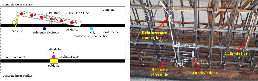
FIGURE 3. Anode-ladder sensor and its general installation appearance.
Based on the design of the anode-ladder sensor, the cathode made of platinum (Pt), reference electrode made of manganese dioxide (MnO2) and reinforcement-connection are set near the anode-ladder before pouring the concrete, while the temperature probe (PT 1,000) is encapsulated in the anode-ladder. Therefore, the electrical macrocell parameters of anodes are divided into five types for the same temperature, which are the macrocell parameters between the single anode and cathode, single anode and reference electrode, single anode and reinforcement-connection, two neighboring anodes, as well as temperature.
In detail, when data is measured by the acquisition device, the data collected include the macrocell potential, macrocell current, resistance, and temperature of concrete specimens. The macrocell potentials are the voltage values of anodes relative to the cathode, reference electrode and reinforcement-connection, respectively. Macrocell currents are the anode values relative to the cathode and the internal reinforcement-connection, while the resistances are values of the concrete between anodes. In one test, a total of 40 parameters are collected, and the specification for the parameters are shown in Tables 1–3.
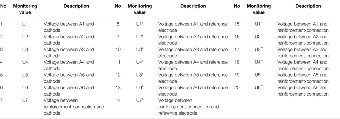
TABLE 1. Voltage values collected by the anode-ladder sensor.
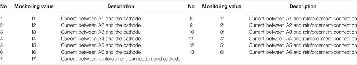
TABLE 2. Current values collected by the anode-ladder sensor.
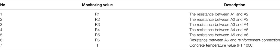
TABLE 3. Resistance values collected by the anode-ladder sensor.
Evaluation Methods
Based on the results of laboratory tests, anodes of 150 mV and 15 μA buried in dry concrete relative to cathode after a short circuit time of 5 s are used as limit values for the activity of the single anode under the usual conditions, and the limit value may be larger when the anode-ladder sensor was set up in a wet environment, such as marine environment (Raupach et al., 2001; S+R Sensortec GMBH Munich, 2009). This conclusion can be used to determine whether the anode is active and to predict the critical depth related to reinforcement corrosion. Generally, current value is used as the main evaluation index to determine whether the anode is active or not.
Another standard to determine the corrosion state of the reinforcement is the half-cell potential inspection method proposed by the ASTM standard C876-09 (ASTM International C 876-09), which involves using a copper-copper sulfate half-cell at the wet concrete surface to measure the half-cell potential of reinforcing steel related to the concrete outer surface. According to the ASTM standard C 876-09, if the half-cell potential is less than −0.35 V, then there is a 90% probability of active corrosion; if the half-cell potential is positive or between −0.35 and −0.2 V, no reliable conclusions can be drawn from the measurement; if the half-cell potential is in the range of −0.2–0 V, there is a 90% probability of no active corrosion being present. The expression above can be summarized as in Table 4, which can be used as a reference to analyze the monitoring data of the anode-ladder-system and to evaluate the risk of corrosion of reinforcing steel.

TABLE 4. Corrosion probability of reinforcing steel.
Application of Anode-ladder-system for Newly Built High-Piled Wharf
Engineering Description
The South 27# Wharf is a high-piled wharf under construction in the Tianjin Port of China, which is designed for bulk cargo transportation. The mechanical properties of this wharf structure are designed for berthing 300,000 DWT bulk carriers. The South 27# wharf is 390 m long and 75 m wide, and it consists of three continuous parts: a 390 m main wharf platform and two 73.3 m side approach bridges. The main wharf platform, which consists of nine 65 m-wide structural segments, is divided into a front platform and back platform based on the operational requirements. The front platform is 36.5 m wide, and the back platform is 38.5 m wide. Each structural segment is uniform. The top elevation of the wharf is 7.5 m, and the depth of water at the wharf apron is −24.8 m. Three crane tracks are set up on the front platform, and the track beams are supported by steel pipe piles with 1.2-m diameters, whereas steel pipe piles with 1.0-m diameters are used in the remaining locations of the front platform. The beams in the back platform are supported by 650 × 650 mm prestressed reinforced-concrete square piles. The uniform loads used for the design are 30 kPa from the wharf apron to 18.5 m, 50 kPa from 18.5 to 36.5 m, and 80 kPa from 36.5 to 75.0 m. The cranes, model 40t-45m, are set on the front platform. The standard value of the mooring force for a bollard is 1,179 kN based on the 200,000 DWT bulk carriers with a wind speed of 24.4 m/s and 1,379 kN according to 300,000 DWT bulk carriers with the same wind speed.
The devised anode-ladder-system will be set up on the second structural segment of this new-built wharf, and the structural drawing of the wharf is shown in Figure 4. For the structural durability monitoring (SDM), one anode-ladder sensor was set up at the red mark in Figure 4. Based on the sensor, the corrosion risk of the reinforced-concrete specimens can be monitored in real time.
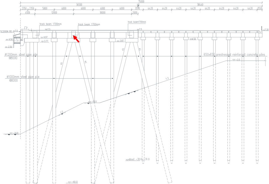
FIGURE 4. Cross section of the South 27# Wharf.
Anode-ladder Sensor Setup and Data Measurement
The anode-ladder sensors for structural durability monitoring of the South 27# Wharf are respectively placed on the track beam of the front platform, and the beams are all precast by high performance C45F300 concrete. The anode-ladder sensor is set in the concrete cover layer (60 mm) on the side of the beam near the bottom surface, and the distance between the outer edge of A1 rod and the outside surface of the beam is 10 mm. All of them are in the splash area of the wharf. The sensor is first installed on the reinforcement cage, and the concrete is cast and cured. Next, the precast specimens are transported to the field for installation when the maintenance is completed. During the construction of the wharf surface layer, the sensor terminal box was embedded in the concrete, which is also protected by the stainless-steel shell. The surface of the steel shell is parallel to the upper surface of the wharf surface layer. After the upper cover of the shell is opened by unscrewing, the sensor terminal box can be seen, and data collection can be carried out with device. Anode-ladder sensor installation, protection, and field data acquisition are shown in Figure 5.
FIGURE 5. Installation of anode-ladder sensor and field data acquisition.
The data from the anode-ladder sensors were collected after wharf completion. The construction of the South 27# Wharf began in early 2016, and the main structure was completed in October 2017. The data collection for the anode-ladder sensors in this project started in October 2017, and was operated for 14 days. Data has been collected continuously for 40 months using the measuring device of HMG 7 with the set of short circuit time of 5 s.
Long-Term Monitoring Data and Evaluation
The monitoring data obtained from the anode-ladder sensor includes voltage, current, resistance, temperature, and other parameters. According to the evaluation methods mentioned above and the technical parameters provided by the manufacturer, the current value of monitoring is often used to determine the status of anodic depassivation or corrosion. At present, it is generally believed that an anode that is buried in dry concrete is in a passive state if the measured current between the anode and cathode is much less than 15 μA; if the current is more than 15 μA, it is considered active. Nevertheless, the limit value may be larger when the anode-ladder sensor was set up in a wet environment, such as marine environment, and there is no uniform standard for the current value in this condition, including the voltage and resistance values. Monitoring data from the anode-ladder sensor during the 40 months of this project is analyzed with emphasis on the current values, and a correlation analysis of voltage, resistance, and temperature values is also implemented. It is necessary to know the durability status of the front platform in different external environments, according to the monitoring data collected from the anode-ladder sensor set on the front of the second structural segment of the wharf. Additionally, the penetration rate of chloride ion and the corrosion state of reinforcement can be known by the comprehensive analysis of monitoring data.
The anode-ladder sensor installed on the track beam of the front platform is 16.5 m away from the front of the wharf and 4.5 m away above the sea surface. After data processing, the time histories of current values for each anode relative to cathode or reinforcement are shown in Figure 6 and Figure 7. It can be seen from Figure 6 that the current value of anode A1 and A2 relative to the cathode exceeded 15 μA from april to July 2018, regardless of the current direction, and gradually recovered to 10 μA during the following months, except for some local trip points. Based on the standard that a current value greater than 15 μA indicates anode depassivation, it can be determined that the depassivation of anode A1 and A2 occurs during April to July 2018. That means that the chloride ion permeated to the depth of anode A2. However, from the monitoring data for the following months, it can be determined that the anodes A1 and A2 are still in the state of passivation because the current value is less than 15 μA. These two conclusions are contradictory. In order to understand this contradiction, the collected temperature data is considered. As can be seen from Figure 6, during the period from April to July 2018, the temperature continued to rise, and the current value of anode A1 and A2 relative to the cathode was greater than 15 μA, following which the current value returns below 15 μA with the drop in temperature. The author believes that the cause of this contradiction is the variation in the ambient temperature, and the depassivation of anode A1 and A2 cannot be determined absolutely based on the current value greater than 15 μA during April to July 2018. Moreover, the track beam was coated with an anticorrosive substance, and the chloride ion permeation depth could not reach A1 and A2, which can also be confirmed by field detection. From the field inspection, it is clear that there are no signs of breakage of the anticorrosive coating. Therefore, the author believes that the anodes A1 and A2 are still passivated.
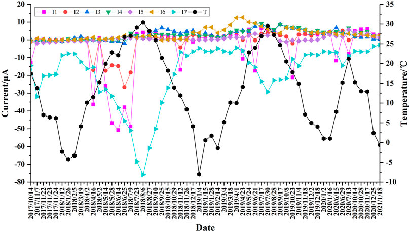
FIGURE 6. Current between anode and cathode.

FIGURE 7. Current between anode and reinforcement-connection.
Furthermore, from the current history between the anode and the reinforcement-connection (Figure 7), the current values of anode A2∼A6 relative to the reinforcement-connection are all less than 10 μA except for anode A1 regardless of the current direction. The current value of anode A1 is larger than 15 μA at a few instances, while most of the current values do not exceed 15 μA. That is like the behavior of the current between anodes and cathode. Based on the above analysis, all the anodes are in the passivation state.
From the processed data, the voltage between the anodes and cathode was obtained, along with the voltage of anodes relative to the reference electrode and reinforcement-connection. Additionally, the resistance between two neighboring anodes was obtained, and their detailed time history curves are shown in Figures 8–11. It can be seen from Figure 8 that the behavior of the voltage is almost consistent with that of the current values above. From April to July in 2018, the voltages of anode A1 and A2 also showed fluctuations, with some voltage values reaching 625 mV, and then decreased gradually until till it fell to within 20 mV. In the following days, the voltage values increased to positive and gradually to 150 mV, except at some trip points, but did not exceed 150 mV. However, certain voltage values of anode A3, A4, and A6 relative to the cathode slightly exceed 150 mV during this period. The voltage values of each anode relative to the reference electrode and reinforcement-connection also show a similar behavior (Figure 9 and Figure 10). Therefore, the value of 150 mV cannot be chosen as the critical limit to determine the activation of anode used in the marine environment, and maybe 300 mV of anode to cathode is more suitable. Because it is considered that the fluctuation of the voltage is caused by ambient temperature, not the depassivation of the anode, which is also proved by field inspection. As the follow-up monitoring data increases, there are multiple seasonal alternation cycles, which may further verify the above conclusions.
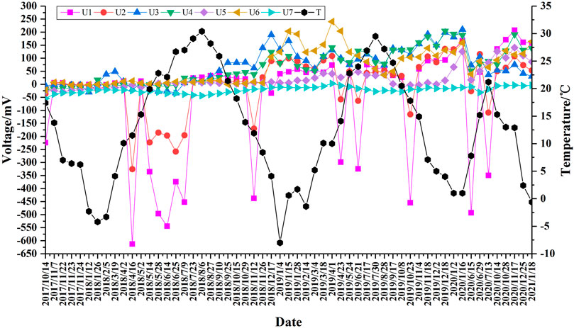
FIGURE 8. Voltage between anode and cathode.
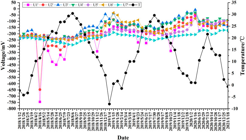
FIGURE 9. Voltage between anode and reference electrode.
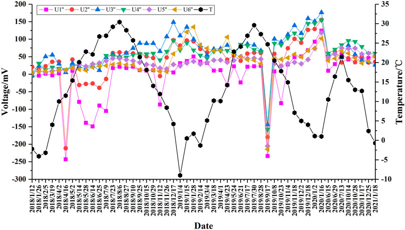
FIGURE 10. Voltage between anode and reinforcement-connection.
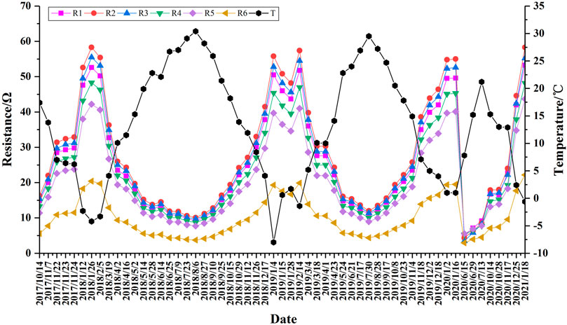
FIGURE 11. Resistance between anodes.
As can be seen from Figure 11, the distribution of resistance values among the anodes is quite regular, and the trend of resistance change opposes the trend of temperature change; that is, when the temperature rises, the resistance drops, and when the temperature drops, the resistance rises. This also indicates that the performance of the installed anode-ladder sensor is reasonable, and the monitoring data is reliable.
Conclusion
Durability monitoring of concrete structures in a marine environment is an important means to extend the service life of structures and an important part of the durability design and redesign of concrete structures. At present, researches on durability monitoring and data analysis of coastal wharf structure, especially on long-term durability monitoring data analysis and processing, is deficient. In this study, based on the newly built South 27# Wharf in the Tianjin Port of China, the anode-ladder sensors were set separately in the track beam of the front platform and the beam of the back platform, which are used to monitor the durability of the wharf structure for a long time. By long-term continuous monitoring, the durability monitoring data from the anode-ladder sensors set in the wharf structure has been collected for 40 consecutive months, with an average data interval of 14 days. The monitoring data includes a total of 40 parameters such as the macrocell current, macrocell voltage, resistance, and temperature. Through the processing and analysis of the monitoring data, the following conclusions are obtained:
(1) Data from the anode-ladder sensor set in the track beam of the front platform showed that the current of anode A1 and A2 relative to the cathode exceeded 15 μA during the four-month period, which indicates the depassivation of anode A1 and A2. However, based on the analysis, it is identified to be a false image caused mainly by the variation in environmental temperature, because the four months mentioned above are in the spring and summer seasons, and the temperature keeps rising.
(2) The resistance of concrete is significantly affected by the variation in temperature, and the increase in temperature will cause a drop in concrete resistance.
(3) Although the anode-ladder-system can monitor corrosion risk of the harbor concrete structure caused by chloride ions. However, under the influence of concrete temperature and humidity, interference data may appear, which may affect the credibility of the conclusions. Therefore, the monitoring data of current, voltage, resistance, and temperature should be combined to determine the activation state of the anode, and it cannot be determined simply by the current value.
Data Availability Statement
The raw data supporting the conclusion of this article will be made available by the authors, without undue reservation.
Author Contributions
Investigation, Conceptualization, HBL; Writing--riginal draft preparation, HBL; Writing--review and editing, BZ; Data curation, HCL; Investigation, ZJ. All authors have read and agreed to the published version of the manuscript.
Funding
This research work was jointly supported by the Fundamental Research Funds for Central Public Research Institutes (Grant number TKS190407 and TKS180204) and Tianjin Transportation Science and Technology Development Project (Grant number 2020-09).
Conflict of Interest
The authors declare that the research was conducted in the absence of any commercial or financial relationships that could be construed as a potential conflict of interest.
Acknowledgments
The authors would like to thank the Tianjin Research Institute of Water Transport Engineering, MOT and its financial support.
References
Ahmad, S. (2003). Reinforcement Corrosion in concrete Structures, its Monitoring and Service Life Prediction-Aa Review. Cement Concrete Composites 25 (4-5), 459–471. doi:10.1016/s0958-9465(02)00086-0
Arndt, R. W., Cui, J., and Huston, D. R. (2011). Monitoring of Reinforced concrete Corrosion and Deterioration by Periodic Multi-Sensor Non-destructive Evaluation. AIP Conf. Proc. 1335 (1), 1371–1378. doi:10.1063/1.3592092
ASTM International C 876-09 (2009). Standard Test Method for Corrosion Potential of Uncoated Reinforcing Steel in concrete. Available online: http://www.astm.org/cgi-bin/resolver.cgi?C876-15 (Accessed on Dec 12, 2020).
Basheer, P. A. M., Chidiact, S. E., and Long, A. E. (1996). Predictive Models for Deterioration of concrete Structures. Construction Building Mater. 10 (1), 27–37. doi:10.1016/0950-0618(95)00092-5
Engelund, S., Mohr, L., and Edvardsen, C. (2000). General Guidelines for Durability Design and Redesign: DuraCrete - Probabilistic Performance Based Durability Design of concrete Structures (Contract BRPR-CT95-0132, Project BE95-1347). 2 ed. (Lyngby, Denmark: CUR), 90–95.
Glass, G. K., and Buenfeld, N. R. (2000). Chloride-induced Corrosion of Steel in concrete. Prog. Struct. Engng Mater. 2 (4), 448–458. doi:10.1002/pse.54
Jin, Z., Zhao, T., Zhang, P., and Gao, S. (2013). Durability Monitoring of concrete Structure of Subsea Tunnel. J. Chin. Ceram. Soc. 41 (2), 205–210. doi:10.7521/j.issn.0454–5648.2013.02.13
Kassir, M. K., and Ghosn, M. (2002). Chloride-induced Corrosion of Reinforced concrete Bridge Decks. Cement Concrete Res. 32 (1), 139–143. doi:10.1016/s0008-8846(01)00644-5
Keddam, M., Takenouti, H., Nóvoa, X. R., Andrade, C., and Alonso, C. (1997). Impedance Measurements on Cement Paste. Cement Concrete Res. 27 (8), 1191–1201. doi:10.1016/s0008-8846(97)00117-8
McCarter, W. J., Chrisp, T. M., Starrs, G., Basheer, P. A. M., and Blewett, J. (2005). Field Monitoring of Electrical Conductivity of Cover-Zone concrete. Cement Concrete Composites 27 (7-8), 809–817. doi:10.1016/j.cemconcomp.2005.03.008
Melchers, R. E., and Li, C. Q. (2006). Phenomenological Modeling of Reinforcement Corrosion in marine Environments. Aci Mater. J. 103 (1), 25–32. doi:10.14359/15124
Pech-Canul, M. A., and Castro, P. (2002). Corrosion Measurements of Steel Reinforcement in concrete Exposed to a Tropical marine Atmosphere. Cement Concrete Res. 32 (3), 491–498. doi:10.1016/s0008-8846(01)00713-x
Raupach, M. (1996). Chloride-induced Macrocell Corrosion of Steel in concrete-theoretical Background and Practical Consequences. Construction Building Mater. 10 (5), 329–338. doi:10.1016/0950-0618(95)00018-6
Raupach, M. (2009). Corrosion of Steel Reinforcement in Concrete. Mater. Corrosion 60 (2), 77. doi:10.1002/maco.200990004
Raupach, M., and Schießl, P. (2001). Macrocell Sensor Systems for Monitoring of the Corrosion Risk of the Reinforcement in concrete Structures. NDT E Int. 34 (6), 435–442. doi:10.1016/s0963-8695(01)00011-1
S+R Sensortec GMBH Munich (2009). Specification of Anode Ladders "Corrosion Monitoring for RC-Structures, Germany. Available online: http://www.sensortec.de/images/pdf/Flyer_Corrosion_Monitoring__eng.pdf (Accessed on Dec 12, 2020).
Tomosawa, F. (2009). Japan's Experiences and Standards on the Durability Problems of Reinforced concrete Structures. Ijstructe 1 (1), 1–12. doi:10.1504/ijstructe.2009.030022
Xu, C., Li, Z., and Jin, W. (2013). A New Corrosion Sensor to Determine the Start and Development of Embedded Rebar Corrosion Process at Coastal concrete. Sensors 13 (10), 13258–13275. doi:10.3390/s131013258
Zhang, P., Zhao, T., Jin, Z., and Zhao, J. (2009). “Application of Durability Sensors in Reinforced Concrete Liner of Subsea Tunnel,” in 2009 International Conference on Measuring Technology and Mechatronics Automation, Zhangjiajie, China, April 11–12, 2009 (Los Alamitos, CA: Institute Of Electrical And Electronics Engineers). 1, 12–15. doi:10.1109/ICMTMA.2009.108
Keywords: structural durability monitoring, high-piled wharf, anode-ladder, reinforcement, corrosion, concrete
Citation: Liu H, Zhang B, Liu H and Ji Z (2021) Analysis of Long-Term Durability Monitoring Data of High-Piled Wharf with Anode-Ladder Sensors Embedded in Concrete. Front. Mater. 8:703347. doi: 10.3389/fmats.2021.703347
Received: 30 April 2021; Accepted: 18 June 2021;
Published: 01 July 2021.
Edited by:
Chun-Xu Qu, Dalian University of Technology, ChinaCopyright © 2021 Liu, Zhang, Liu and Ji. This is an open-access article distributed under the terms of the Creative Commons Attribution License (CC BY). The use, distribution or reproduction in other forums is permitted, provided the original author(s) and the copyright owner(s) are credited and that the original publication in this journal is cited, in accordance with accepted academic practice. No use, distribution or reproduction is permitted which does not comply with these terms.
*Correspondence: Baohua Zhang, ODU1OTY4ODFAcXEuY29t